2008 INFINITI QX56 engine
[x] Cancel search: enginePage 1898 of 4083
ENGINE UNITEM-95
< DISASSEMBLY AND ASSEMBLY >
C
DE
F
G H
I
J
K L
M A
EM
NP
O
• Install the main bearing caps with the main bearings removed, and
tighten the bolts to the specified torque. Refer to EM-82, "
Disas-
sembly and Assembly".
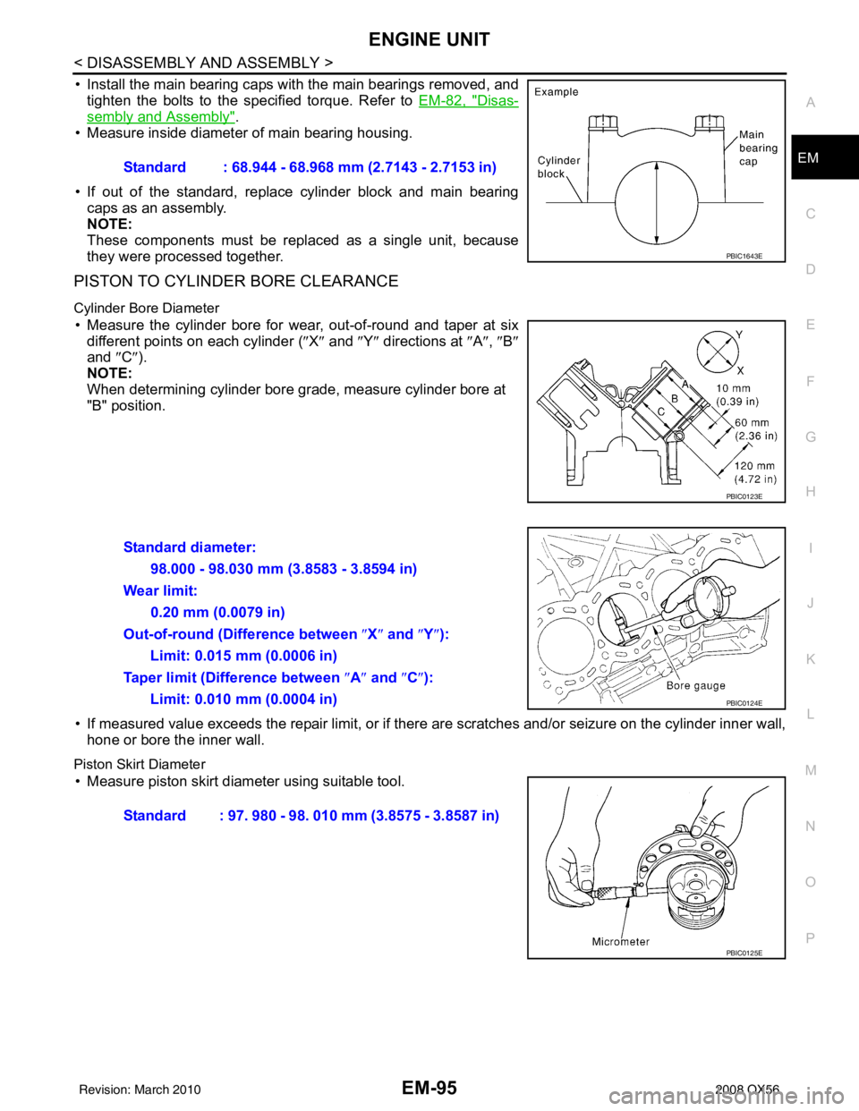
• Measure inside diameter of main bearing housing.
• If out of the standard, replace cylinder block and main bearing caps as an assembly.
NOTE:
These components must be replaced as a single unit, because
they were processed together.
PISTON TO CYLINDER BORE CLEARANCE
Cylinder Bore Diameter
• Measure the cylinder bore for wear, out-of-round and taper at six
different points on each cylinder ( ″X″ and ″Y″ directions at ″A″ , ″B″
and ″C ″).
NOTE:
When determining cylinder bore grade, measure cylinder bore at
"B" position.
• If measured value exceeds the repair limit, or if ther e are scratches and/or seizure on the cylinder inner wall,
hone or bore the inner wall.
Piston Skirt Diameter
• Measure piston skirt diameter using suitable tool. Standard : 68.944 - 68.968 mm (2.7143 - 2.7153 in)
PBIC1643E
PBIC0123E
Standard diameter:
98.000 - 98.030 mm (3.8583 - 3.8594 in)
Wear limit: 0.20 mm (0.0079 in)
Out-of-round (Difference between ″X″ and ″Y″ ):
Limit: 0.015 mm (0.0006 in)
Taper limit (Difference between ″A ″ and ″C ″):
Limit: 0.010 mm (0.0004 in)
PBIC0124E
Standard : 97. 980 - 98. 010 mm (3.8575 - 3.8587 in)
PBIC0125E
Revision: March 2010 2008 QX56
Page 1899 of 4083
EM-96
< DISASSEMBLY AND ASSEMBLY >
ENGINE UNIT
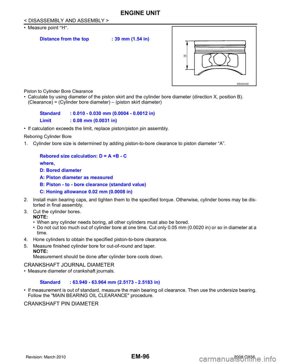
• Measure point ″H″.
Piston to Cylinde r Bore Clearance
• Calculate by using diameter of the piston skirt and the cylinder bore diameter (direction X, position B).
(Clearance) = (Cylinder bore diameter) – (piston skirt diameter)
• If calculation exceeds the limit, replace piston/piston pin assembly.
Reboring Cylinder Bore
1. Cylinder bore size is determined by adding pi ston-to-bore clearance to piston diameter “A”.
2. Install main bearing caps, and tighten them to the specified torque. Otherwise, cylinder bores may be dis-
torted in final assembly.
3. Cut the cylinder bores. NOTE:
• When any cylinder needs boring, all other cylinders must also be bored.
• Do not cut too much out of cylinder bore at one time. Cut only 0.05 mm (0.0020 in) or so in diameter at atime.
4. Hone cylinders to obtain the specified piston-to-bore clearance.
5. Measure finished cylinder bore for out-of-round and taper. NOTE:
Measurement should be done after cylinder bore cools down.
CRANKSHAFT JOURNAL DIAMETER
• Measure diameter of crankshaft journals.
• If measurement is out of standard, measure the ma in bearing oil clearance. Then use the undersize bearing.
Follow the "MAIN BEARING OIL CLEARANCE" procedure.
CRANKSHAFT PIN DIAMETER
Distance from the top : 39 mm (1.54 in)
KBIA2545E
Standard : 0.010 - 0.030 mm (0.0004 - 0.0012 in)
Limit : 0.08 mm (0.0031 in)
Rebored size calculation: D = A +B - C
where,
D: Bored diameter
A: Piston diameter as measured
B: Piston - to - bore clearance (standard value)
C: Honing allowance 0.02 mm (0.0008 in)
Standard : 63.940 - 63.964 mm (2.5173 - 2.5183 in)
Revision: March 2010 2008 QX56
Page 1900 of 4083

ENGINE UNITEM-97
< DISASSEMBLY AND ASSEMBLY >
C
DE
F
G H
I
J
K L
M A
EM
NP
O
• Measure diameter of crankshaft pin using suitable tool.
• If measurement is out of standard, measure connecting rod bear-
ing oil clearance. Then use undersize bearing. Follow the "CON-
NECTING ROD BUSHING OIL CLEARANCE (SMALL END)"
procedure.
OUT-OF-ROUND AND TAPER OF CRANKSHAFT
• Measure dimensions at four di fferent points as shown on each
journal and pin.
• Out-of-roundness is indicated by the difference in dimension
between ″X″ and ″Y″ at ″A″ and ″B″ .
• Taper is indicated by the difference in dimension between ″A ″ and
″ B″ at ″X ″ and ″Y″ .
• If measured value exceeds the standard, correct or replace crankshaft.
• If corrected, measure the bearing oil clearance of the corrected journal or pin. Then select the main bearing or connecting rod bearing. Follow the "MAIN BEA RING OIL CLEARANCE" or " CONNECTING ROD BEAR-
ING OIL CLEARANCE" procedure.
CRANKSHAFT RUNOUT
• Place a V-block on a precise flat table to support the journals on both ends of the crankshaft.
• Measure at No. 3 journal using suitable tool.
• While rotating crankshaft, read the movement of the pointer.
• Half of the movement shows the runout.
• If measurement exceeds the limit, replace crankshaft.
CONNECTING ROD BEARING OIL CLEARANCE
Method of Measurement
• Install connecting rod bearings to the connecting rod and cap. Tighten connecting rod bolts to the specified
torque. Refer to EM-82, "
Disassembly and Assembly".
Measure inside diameter of connecting rod bearing.
(Oil clearance) = (Inside diameter of connecting rod bearing) –
(Crankshaft pin diameter)
• If clearance cannot be adjusted wit hin the standard, grind crank-
shaft pin and use undersized bearing. Refer to EM-101, "
How to
Select Piston and Bearing".
Standard : 53.956 - 53.974 mm (2.1243 - 2.1250 in)
PBIC0127E
Limit
Out-of-round (Difference between ″X ″ and ″ Y″)
: 0.002 mm (0.0001 in)
Taper (Difference between ″ A″ and ″B ″)
: 0.002 mm (0.0001 in)
PBIC1685E
Limit : Less than 0.05 mm (0.002 in)
PBIC0129E
Standard : 0.020 - 0.039 mm (0.0008 - 0.0015 in)
Limit : 0.055 mm (0.0022 in)
PBIC1642E
Revision: March 2010 2008 QX56
Page 1901 of 4083
EM-98
< DISASSEMBLY AND ASSEMBLY >
ENGINE UNIT
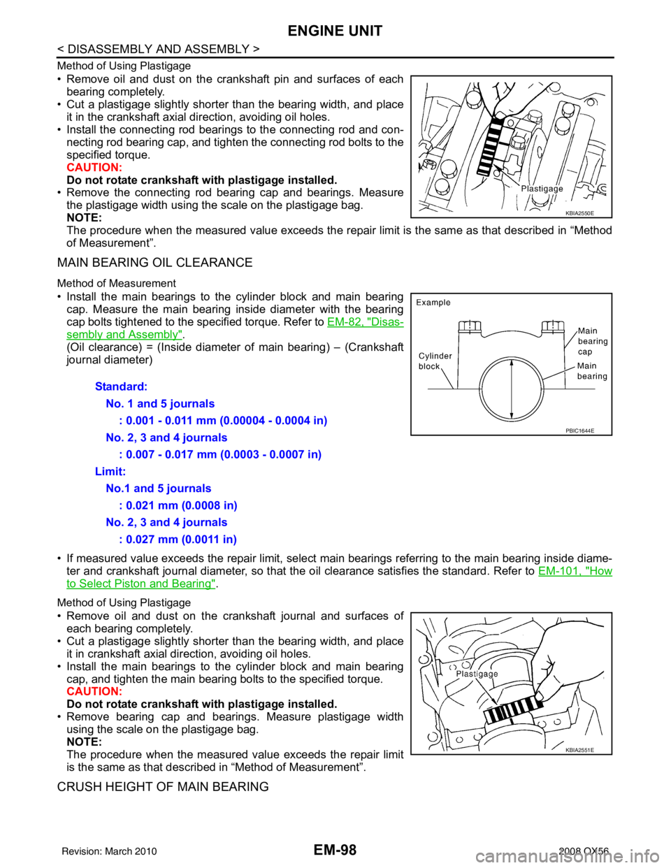
Method of Using Plastigage
• Remove oil and dust on the crankshaft pin and surfaces of eachbearing completely.
• Cut a plastigage slightly shorter than the bearing width, and place
it in the crankshaft axial direction, avoiding oil holes.
• Install the connecting rod beari ngs to the connecting rod and con-
necting rod bearing cap, and tighten the connecting rod bolts to the
specified torque.
CAUTION:
Do not rotate crankshaft with plastigage installed.
• Remove the connecting rod bear ing cap and bearings. Measure
the plastigage width using the scale on the plastigage bag.
NOTE:
The procedure when the measured value exceeds the repair limit is the same as that described in “Method
of Measurement”.
MAIN BEARING OIL CLEARANCE
Method of Measurement
• Install the main bearings to the cylinder block and main bearing cap. Measure the main bearing inside diameter with the bearing
cap bolts tightened to the specified torque. Refer to EM-82, "
Disas-
sembly and Assembly".
(Oil clearance) = (Inside diameter of main bearing) – (Crankshaft
journal diameter)
• If measured value exceeds the repair limit, select main bearings referring to the main bearing inside diame-
ter and crankshaft journal diameter, so that the oil clearance satisfies the standard. Refer to EM-101, "
How
to Select Piston and Bearing".
Method of Using Plastigage
• Remove oil and dust on the crankshaft journal and surfaces of
each bearing completely.
• Cut a plastigage slightly shorter than the bearing width, and place it in crankshaft axial direction, avoiding oil holes.
• Install the main bearings to the cylinder block and main bearing cap, and tighten the main bearing bolts to the specified torque.
CAUTION:
Do not rotate crankshaft with plastigage installed.
• Remove bearing cap and bearings. Measure plastigage width using the scale on the plastigage bag.
NOTE:
The procedure when the measured value exceeds the repair limit
is the same as that descri bed in “Method of Measurement”.
CRUSH HEIGHT OF MAIN BEARING
KBIA2550E
Standard:
No. 1 and 5 journals : 0.001 - 0.011 mm (0.00004 - 0.0004 in)
No. 2, 3 and 4 journals : 0.007 - 0.017 mm (0.0003 - 0.0007 in)
Limit: No.1 and 5 journals : 0.021 mm (0.0008 in)
No. 2, 3 and 4 journals : 0.027 mm (0.0011 in)
PBIC1644E
KBIA2551E
Revision: March 2010 2008 QX56
Page 1902 of 4083
ENGINE UNITEM-99
< DISASSEMBLY AND ASSEMBLY >
C
DE
F
G H
I
J
K L
M A
EM
NP
O
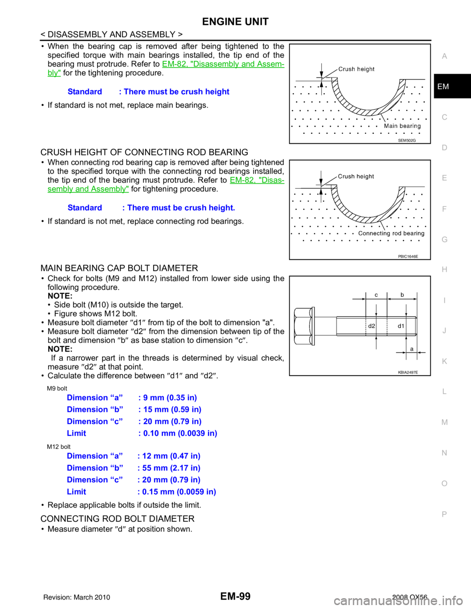
• When the bearing cap is removed after being tightened to the
specified torque with main bearings installed, the tip end of the
bearing must protrude. Refer to EM-82, "
Disassembly and Assem-
bly" for the tightening procedure.
• If standard is not met, replace main bearings.
CRUSH HEIGHT OF CONNECTING ROD BEARING
• When connecting rod bearing cap is removed after being tightened to the specified torque with the connecting rod bearings installed,
the tip end of the bearing must protrude. Refer to EM-82, "
Disas-
sembly and Assembly" for tightening procedure.
• If standard is not met, replace connecting rod bearings.
MAIN BEARING CAP BOLT DIAMETER
• Check for bolts (M9 and M12) installed from lower side using the following procedure.
NOTE:
• Side bolt (M10) is outside the target.
• Figure shows M12 bolt.
• Measure bolt diameter ″ d1″ from tip of the bolt to dimension "a".
• Measure bolt diameter ″d2″ from the dimension between tip of the
bolt and dimension ″b ″ as base station to dimension ″c″ .
NOTE:
If a narrower part in the threads is determined by visual check,
measure ″d2″ at that point.
• Calculate the difference between ″d1″ and ″d2″ .
M9 bolt
M12 bolt
• Replace applicable bolts if outside the limit.
CONNECTING ROD BOLT DIAMETER
• Measure diameter ″d ″ at position shown.
Standard : There must be crush height
SEM502G
Standard : There must be crush height.
PBIC1646E
KBIA2497E
Dimension “a” : 9 mm (0.35 in)
Dimension “b” : 15 mm (0.59 in)
Dimension “c” : 20 mm (0.79 in)
Limit : 0.10 mm (0.0039 in)
Dimension “a” : 12 mm (0.47 in)
Dimension “b” : 55 mm (2.17 in)
Dimension “c” : 20 mm (0.79 in)
Limit : 0.15 mm (0.0059 in)
Revision: March 2010
2008 QX56
Page 1903 of 4083
EM-100
< DISASSEMBLY AND ASSEMBLY >
ENGINE UNIT
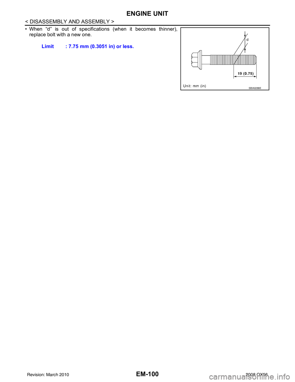
• When “d” is out of specifications (when it becomes thinner),
replace bolt with a new one.
Limit : 7.75 mm (0.3051 in) or less.
SBIA0286E
Revision: March 2010 2008 QX56
Page 1922 of 4083
EX-1
ENGINE
C
DE
F
G H
I
J
K L
M
SECTION EX
A
EX
N
O P
CONTENTS
EXHAUST SYSTEM
PRECAUTION ....... ........................................2
PRECAUTIONS .............................................. .....2
Precaution for Supplemental Restraint System
(SRS) "AIR BAG" and "SEAT BELT PRE-TEN-
SIONER" ............................................................. ......
2
Precaution Necessary for Steering Wheel Rota-
tion After Battery Disconnect ............................... ......
2
Precaution for Liquid Gasket .....................................3
PREPARATION ............................................4
PREPARATION ..................................................4
Special Service Tool ............................................ .....4
Commercial Service Tool .........................................4
ON-VEHICLE MAINTENANCE .....................5
EXHAUST SYSTEM ...........................................5
Checking Exhaust System ................................... .....5
ON-VEHICLE REPAIR ..................................6
EXHAUST SYSTEM ...........................................6
Removal and Installation ..................................... .....6
Revision: March 2010 2008 QX56
Page 1923 of 4083
EX-2
< PRECAUTION >
PRECAUTIONS
PRECAUTION
PRECAUTIONS
Precaution for Supplemental Restraint System (SRS) "AIR BAG" and "SEAT BELT
PRE-TENSIONER"
INFOID:0000000004857579
The Supplemental Restraint System such as “A IR BAG” and “SEAT BELT PRE-TENSIONER”, used along
with a front seat belt, helps to reduce the risk or severity of injury to the driver and front passenger for certain
types of collision. This system includes seat belt switch inputs and dual stage front air bag modules. The SRS
system uses the seat belt switches to determine the front air bag deployment, and may only deploy one front
air bag, depending on the severity of a collision and w hether the front occupants are belted or unbelted.
Information necessary to service the system safely is included in the SR and SB section of this Service Man-
ual.
WARNING:
• To avoid rendering the SRS inopera tive, which could increase the risk of personal injury or death in
the event of a collision which would result in air bag inflation, all maintenance must be performed by
an authorized NISSAN/INFINITI dealer.
• Improper maintenance, including in correct removal and installation of the SRS, can lead to personal
injury caused by unintent ional activation of the system. For re moval of Spiral Cable and Air Bag
Module, see the SR section.
• Do not use electrical test equipmen t on any circuit related to the SRS unless instructed to in this
Service Manual. SRS wiring harn esses can be identified by yellow and/or orange harnesses or har-
ness connectors.
PRECAUTIONS WHEN USING POWER TOOLS (AIR OR ELECTRIC) AND HAMMERS
WARNING:
• When working near the Airbag Diagnosis Sensor Unit or other Airbag System sensors with the Igni-
tion ON or engine running, DO NOT use air or electri c power tools or strike near the sensor(s) with a
hammer. Heavy vibration could activate the sensor( s) and deploy the air bag(s), possibly causing
serious injury.
• When using air or electric power tools or hammers , always switch the Ignition OFF, disconnect the
battery, and wait at least 3 minu tes before performing any service.
Precaution Necessary for Steering W heel Rotation After Battery Disconnect
INFOID:0000000004857585
NOTE:
• This Procedure is applied only to models with Intelligent Key system and NATS (NISSAN ANTI-THEFT SYS-
TEM).
• Remove and install all control units after disconnecting both battery cables with the ignition knob in the
″LOCK ″ position.
• Always use CONSULT-III to perform self-diagnosis as a part of each function inspection after finishing work.
If DTC is detected, perform trouble diagnosis according to self-diagnostic results.
For models equipped with the Intelligent Key system and NATS, an electrically controlled steering lock mech-
anism is adopted on the key cylinder.
For this reason, if the battery is disconnected or if the battery is discharged, the steering wheel will lock and
steering wheel rotation will become impossible.
If steering wheel rotation is required when battery pow er is interrupted, follow the procedure below before
starting the repair operation.
OPERATION PROCEDURE
1. Connect both battery cables. NOTE:
Supply power using jumper cables if battery is discharged.
2. Use the Intelligent Key or mechanical key to turn the ignition switch to the ″ACC ″ position. At this time, the
steering lock will be released.
3. Disconnect both battery cables. The steering lock will remain released and the steering wheel can be rotated.
4. Perform the necessary repair operation.
Revision: March 2010 2008 QX56