2008 INFINITI QX56 battery location
[x] Cancel search: battery locationPage 2971 of 4083
PRECAUTIONSRAX-3
< PRECAUTION >
CEF
G H
I
J
K L
M A
B
RAX
N
O P
5. When the repair work is completed, return the ignition switch to the ″LOCK ″ position before connecting
the battery cables. (At this time, the steering lock mechanism will engage.)
6. Perform a self-diagnosis check of al l control units using CONSULT-III.
CautionINFOID:0000000001534572
Observe the following precautions when disassembling and servicing drive shaft.
• Perform work in a location which is as dust-free as possible.
• Before disassembling and servicing, clean the outside of parts.
• Prevention of the entry of foreign objects must be tak en into account during disassembly of the service loca-
tion.
• Disassembled parts must be carefully reassembled in the correct order. If work is interrupted, a clean cover
must be placed over parts.
• Paper shop cloths must be used. Fabric shop cloths must not be used because of the danger of lint adhering to parts.
• Disassembled parts (except for rubber parts) should be cleaned with kerosene which shall be removed by blowing with air or wiping with paper shop cloths.
Revision: March 2010 2008 QX56
Page 3089 of 4083
SCS-6
< FUNCTION DIAGNOSIS >
SUSPENSION CONTROL SYSTEM
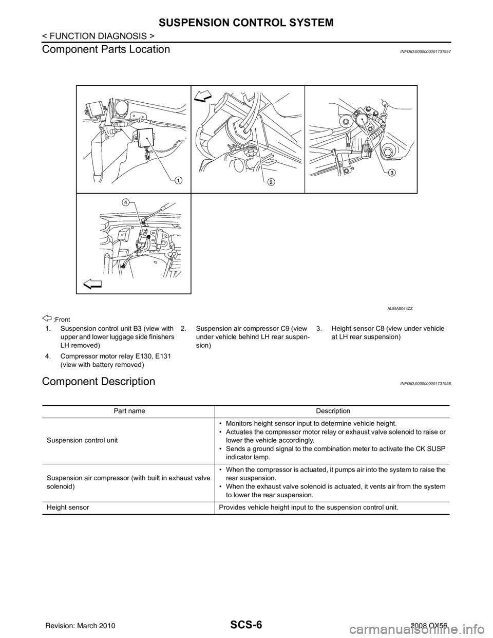
Component Parts Location
INFOID:0000000001731957
:Front
Component DescriptionINFOID:0000000001731958
1. Suspension control unit B3 (view with upper and lower luggage side finishers
LH removed) 2. Suspension air compressor C9 (view
under vehicle behind LH rear suspen-
sion) 3. Height sensor C8 (view under vehicle
at LH rear suspension)
4. Compressor motor relay E130, E131 (view with battery removed)
ALEIA0044ZZ
Part name Description
Suspension control unit • Monitors height sensor input to determine vehicle height.
• Actuates the compressor motor relay or exhaust valve solenoid to raise or
lower the vehicle accordingly.
• Sends a ground signal to the combination meter to activate the CK SUSP indicator lamp.
Suspension air compressor (with built in exhaust valve
solenoid) • When the compressor is actuated, it pumps air into the system to raise the
rear suspension.
• When the exhaust valve solenoid is actuated, it vents air from the system to lower the rear suspension.
Height sensor Provides vehicle height input to the suspension control unit.
Revision: March 2010 2008 QX56
Page 3140 of 4083
SE-18
< COMPONENT DIAGNOSIS >
THIRD SEAT
THIRD SEAT
Power Supply and Ground Circuit Check for Third Row Power Folding Seat Control
Unit
INFOID:0000000001735718
1.CHECK FUSES AND FUSIBLE LINK
Check for blown fuses or fusible link.
Are any fuses or fusible links blown?
YES >> Install new fuse. Eliminate cause of malfunction if fuse blows again.
NO >> GO TO 2
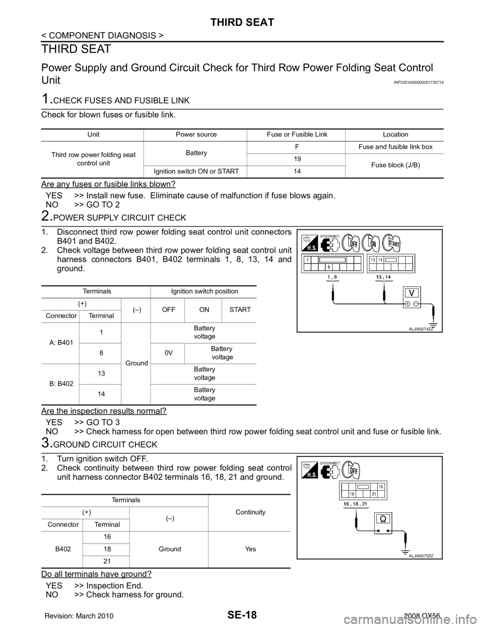
2.POWER SUPPLY CIRCUIT CHECK
1. Disconnect third row power folding seat control unit connectors B401 and B402.
2. Check voltage between third row power folding seat control unit harness connectors B401, B402 terminals 1, 8, 13, 14 and
ground.
Are the inspection results normal?
YES >> GO TO 3
NO >> Check harness for open between third row power folding seat control unit and fuse or fusible link.
3.GROUND CIRCUIT CHECK
1. Turn ignition switch OFF.
2. Check continuity between third row power folding seat control unit harness connector B402 terminals 16, 18, 21 and ground.
Do all terminals have ground?
YES >> Inspection End.
NO >> Check harness for ground.
Unit Power source Fuse or Fusible Link Location
Third row power folding seat control unit Battery
F
Fuse and fusible link box
19 Fuse block (J/B)
Ignition switch ON or START 14
TerminalsIgnition switch position
(+) (–) OFF ON START
Connector Terminal
A: B401 1
Ground Battery
voltage
80 VBattery
voltage
B: B402 13
Battery
voltage
14 Battery
voltage
ALJIA0274ZZ
Te r m i n a l s
Continuity
(+)
(–)
Connector Terminal
B402 16
Ground Yes
18
21
ALJIA0275ZZ
Revision: March 2010 2008 QX56
Page 3326 of 4083

SN
SN-1
DRIVER INFORMATION & MULTIMEDIA
C
DE
F
G H
I
J
K L
M B
SECTION SN
A
O P
CONTENTS
SONAR SYSTEM
BASIC INSPECTION ....... .............................3
DIAGNOSIS AND REPAIR WORKFLOW ..... .....3
Work Flow ........................................................... ......3
INSPECTION AND ADJUSTMENT .....................5
Preliminary Check ............................................... ......5
FUNCTION DIAGNOSIS ...............................6
REAR SONAR SYSTEM ................................ .....6
System Diagram .................................................. ......6
System Description ...................................................6
Component Parts Location ........................................7
Component Description .............................................7
Self-Diagnosis Function ............................................7
FRONT AND REAR SONAR SYSTEM .......... ....10
System Diagram .................................................. ....10
System Description .................................................10
Component Parts Location ......................................11
Component Description ...........................................12
CONSULT-III Function (SONAR) ............................12
COMPONENT DIAGNOSIS .........................13
POWER SUPPLY AND GROUND CIRCUIT .. ....13
Diagnosis Procedure For Rear Sonar System .... ....13
Diagnosis Procedure For Front And Rear Sonar
System ....................................................................
13
SONAR SENSOR CIRCUIT INSPECTION ........15
Description .......................................................... ....15
Diagnosis Procedure (With Rear Sonar System) ....15
Diagnosis Procedure (With Front and Rear Sonar
System) ...................................................................
15
SONAR BUZZER CIRCUIT INSPECTION .........17
Description .......................................................... ....17
Diagnosis Procedure (With Rear Sonar System) ....17
Diagnosis Procedure (With Front and Rear Sonar
System) ...................................................................
17
Component Inspection ......................................... ....18
SONAR SYSTEM OFF SWITCH CIRCUIT IN-
SPECTION ........................................................
19
Description ........................................................... ....19
Diagnosis Procedure (With Rear Sonar System) ....19
Diagnosis Procedure (With Front and Rear Sonar
System) ............................................................... ....
19
Component Inspection .............................................20
ECU DIAGNOSIS .........................................21
SONAR CONTROL UNIT FOR REAR SONAR
SYSTEM ...................... ......................................
21
Reference Value .................................................. ....21
Wiring Diagram ........................................................23
DTC Index ...............................................................30
SONAR CONTROL UNIT FOR FRONT AND
REAR SONAR SYSTEM ...................................
31
Reference Value ......................................................31
Wiring Diagram ........................................................33
DTC Index ...............................................................44
SYMPTOM DIAGNOSIS ..............................45
SONAR SYSTEM SYMPTOMS ........................45
Symptom Table ................................................... ....45
PRECAUTION ..............................................46
PRECAUTION ...................................................46
Precaution for Supplemental Restraint System
(SRS) "AIR BAG" and "SEAT BELT PRE-TEN-
SIONER" ............................................................. ....
46
Precaution Necessary for Steering Wheel Rota-
tion After Battery Disconnect ...................................
46
PREPARATION ...........................................48
PREPARATION .................................................48
Commercial Service Tool .................................... ....48
Revision: March 2010 2008 QX56
Page 3338 of 4083
SN
POWER SUPPLY AND GROUND CIRCUITSN-13
< COMPONENT DIAGNOSIS >
C
DE
F
G H
I
J
K L
M B A
O P
COMPONENT DIAGNOSIS
POWER SUPPLY AND GROUND CIRCUIT
Diagnosis Procedure Fo r Rear Sonar SystemINFOID:0000000001754066
INSPECTION FOR POWER SUPPLY AND GROUND CIRCUIT
1.CHECK FUSES
Check for blown rear sonar system fuses.
Are any fuses blown?
YES >> If fuse is blown, be sure to eliminate cause of malfunction before installing new fuse. Refer to GI-
41, "Circuit Inspection".
NO >> GO TO 2.
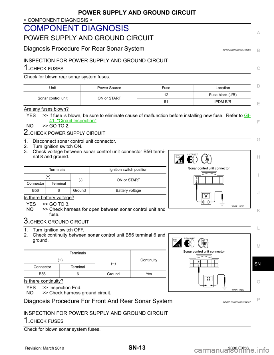
2.CHECK POWER SUPPLY CIRCUIT
1. Disconnect sonar control unit connector.
2. Turn ignition switch ON.
3. Check voltage between sonar control unit connector B56 termi- nal 8 and ground.
Is there battery voltage?
YES >> GO TO 3.
NO >> Check harness for open between sonar control unit and fuse.
3.CHECK GROUND CIRCUIT
1. Turn ignition switch OFF.
2. Check continuity between sonar control unit B56 terminal 6 and ground.
Is there continuity?
YES >> Inspection End.
NO >> Check harness ground circuit.
Diagnosis Procedure For Fron t And Rear Sonar SystemINFOID:0000000001754067
INSPECTION FOR POWER SUPPLY AND GROUND CIRCUIT
1.CHECK FUSES
Check for blown sonar system fuses.
Unit Power Source FuseLocation
Sonar control unit ON or START 12
Fuse block (J/B)
51 IPDM E/R
Terminals Ignition switch position
(+) (-) ON or START
Connector Terminal
B56 8 Ground Battery voltage
WKIA1145E
Te r m i n a l s
Continuity
(+)
(–)
Connector Terminal
B56 6 Ground Yes
WKIA1146E
Revision: March 2010 2008 QX56
Page 3339 of 4083
SN-14
< COMPONENT DIAGNOSIS >
POWER SUPPLY AND GROUND CIRCUIT
Are any fuses blown?
YES >> If fuse is blown, be sure to eliminate cause of malfunction before installing new fuse. Refer to GI-
41, "Circuit Inspection".
NO >> GO TO 2.
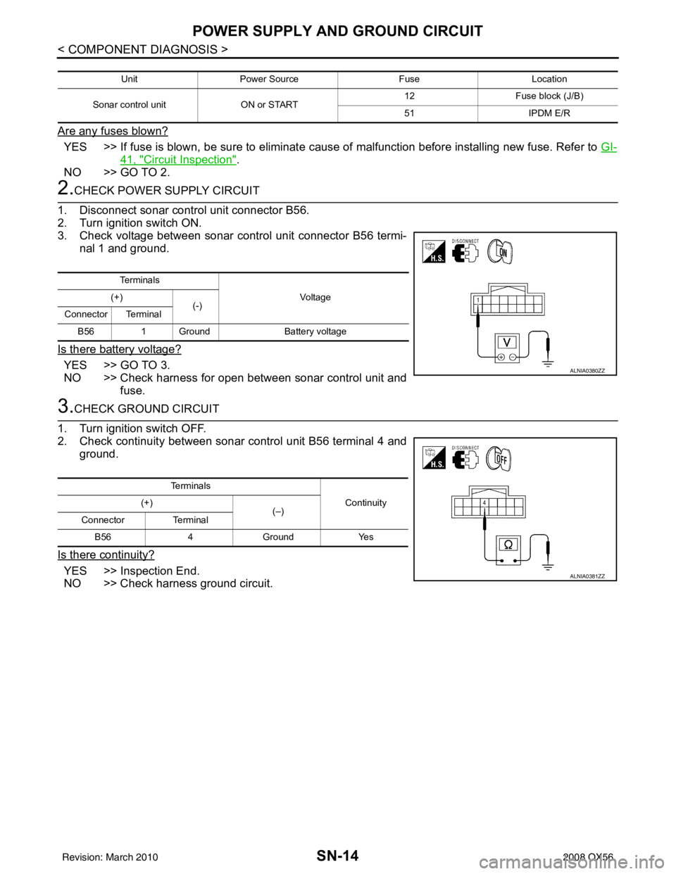
2.CHECK POWER SUPPLY CIRCUIT
1. Disconnect sonar control unit connector B56.
2. Turn ignition switch ON.
3. Check voltage between sonar control unit connector B56 termi- nal 1 and ground.
Is there battery voltage?
YES >> GO TO 3.
NO >> Check harness for open between sonar control unit and fuse.
3.CHECK GROUND CIRCUIT
1. Turn ignition switch OFF.
2. Check continuity between sonar control unit B56 terminal 4 and ground.
Is there continuity?
YES >> Inspection End.
NO >> Check harness ground circuit.
Unit Power Source FuseLocation
Sonar control unit ON or START 12
Fuse block (J/B)
51 IPDM E/R
Te r m i n a l s
Vo l ta g e
(+)
(-)
Connector Terminal
B56 1 Ground Battery voltage
ALNIA0380ZZ
Te r m i n a l s
Continuity
(+)
(–)
Connector Terminal
B56 4Ground Yes
ALNIA0381ZZ
Revision: March 2010 2008 QX56
Page 3492 of 4083
ST-1
STEERING
C
DE
F
H I
J
K L
M
SECTION ST
A
B
ST
N
O P
CONTENTS
STEERING SYSTEM
PRECAUTION ....... ........................................3
PRECAUTIONS .............................................. .....3
Precaution for Supplemental Restraint System
(SRS) "AIR BAG" and "SEAT BELT PRE-TEN-
SIONER" ............................................................. ......
3
Precaution Necessary for Steering Wheel Rota-
tion After Battery Disconnect ............................... ......
3
Precaution for Steering System .......................... ......4
PREPARATION ............................................5
PREPARATION .............................................. .....5
Special Service Tool ........................................... ......5
Commercial Service Tool ..........................................6
FUNCTION DIAGNOSIS ...............................7
HEATED STEERING WHEEL ........................ .....7
System Diagram .................................................. ......7
System Description ...................................................7
Component Parts Location ........................................7
Component Description .............................................8
COMPONENT DIAGNOSIS ..........................9
HEATED STEERING WHEEL ........................ .....9
Wiring Diagram ................................................... ......9
SYMPTOM DIAGNOSIS ..............................12
NOISE, VIBRATION AND HARSHNESS
(NVH) TROUBLESHOOTING ........................ ....
12
NVH Troubleshooting Chart ................................ ....12
ON-VEHICLE MAINTENANCE ....................13
POWER STEERING FLUID ........................... ....13
Checking Fluid Level ........................................... ....13
Checking Fluid Leakage ..........................................13
Air Bleeding Hydraulic System ................................13
ON-VEHICLE REPAIR .................................15
STEERING WHEEL ..........................................15
On-Vehicle Inspection and Service ..................... ....15
POWER STEERING OIL PUMP .......................17
On-Vehicle Inspection and Service .........................17
REMOVAL AND INSTALLATION ...............18
STEERING WHEEL ..........................................18
Removal and Installation ..................................... ....18
TILT SYSTEM ...................................................19
Removal and Installation .........................................19
STEERING COLUMN ........................................20
Removal and Installation .........................................20
POWER STEERING GEAR AND LINKAGE ....23
Removal and Installation .........................................23
POWER STEERING OIL PUMP .......................26
Removal and Installation .........................................26
HYDRAULIC LINE ............................................27
Removal and Installation .........................................27
DISASSEMBLY AND ASSEMBLY ..............29
STEERING COLUMN ........................................29
Disassembly and Assembly ................................. ....29
POWER STEERING GEAR AND LINKAGE ....31
Disassembly and Assembly .....................................31
POWER STEERING OIL PUMP .......................35
Disassembly and Assembly .....................................35
SERVICE DATA AND SPECIFICATIONS
(SDS) ............... .......................................... ...
36
SERVICE DATA AND SPECIFICATIONS
(SDS) .................................................................
36
Steering Wheel .................................................... ....36
Revision: March 2010 2008 QX56
Page 3530 of 4083
STR-1
ENGINE
C
DE
F
G H
I
J
K L
M
SECTION STR
A
STR
N
O P
CONTENTS
STARTING SYSTEM
PRECAUTION ....... ........................................2
PRECAUTIONS .............................................. .....2
Precaution for Supplemental Restraint System
(SRS) "AIR BAG" and "SEAT BELT PRE-TEN-
SIONER" ............................................................. ......
2
Precaution Necessary for Steering Wheel Rota-
tion After Battery Disconnect ............................... ......
2
Precaution for Power Generation Variable Voltage
Control System ..........................................................
3
PREPARATION ............................................4
PREPARATION .............................................. .....4
Special Service Tool ........................................... ......4
Commercial Service Tool ..........................................4
BASIC INSPECTION ....................................5
DIAGNOSIS AND REPAIR WORKFLOW ..... .....5
Work Flow ........................................................... ......5
FUNCTION DIAGNOSIS ...............................8
STARTING SYSTEM ...................................... .....8
System Diagram .................................................. ......8
System Description ...................................................8
Component Parts Location ........................................8
Component Description ............................................9
COMPONENT DIAGNOSIS .........................10
B TERMINAL CIRCUIT .....................................10
Description ........................................................... ....10
Diagnosis Procedure ...............................................10
S CONNECTOR CIRCUIT .................................11
Description ...............................................................11
Diagnosis Procedure ...............................................11
STARTING SYSTEM .........................................12
Wiring Diagram .................................................... ....12
SYMPTOM DIAGNOSIS ..............................16
STARTING SYSTEM .........................................16
Symptom Table ................................................... ....16
ON-VEHICLE REPAIR .................................17
STARTER MOTOR ...........................................17
Removal and Installation ..................................... ....17
SERVICE DATA AND SPECIFICATIONS
(SDS) ............... .......................................... ...
18
STARTER MOTOR ...........................................18
Starter .................................................................. ....18
Revision: March 2010 2008 QX56