2008 INFINITI QX56 battery location
[x] Cancel search: battery locationPage 3537 of 4083

STR-8
< FUNCTION DIAGNOSIS >
STARTING SYSTEM
FUNCTION DIAGNOSIS
STARTING SYSTEM
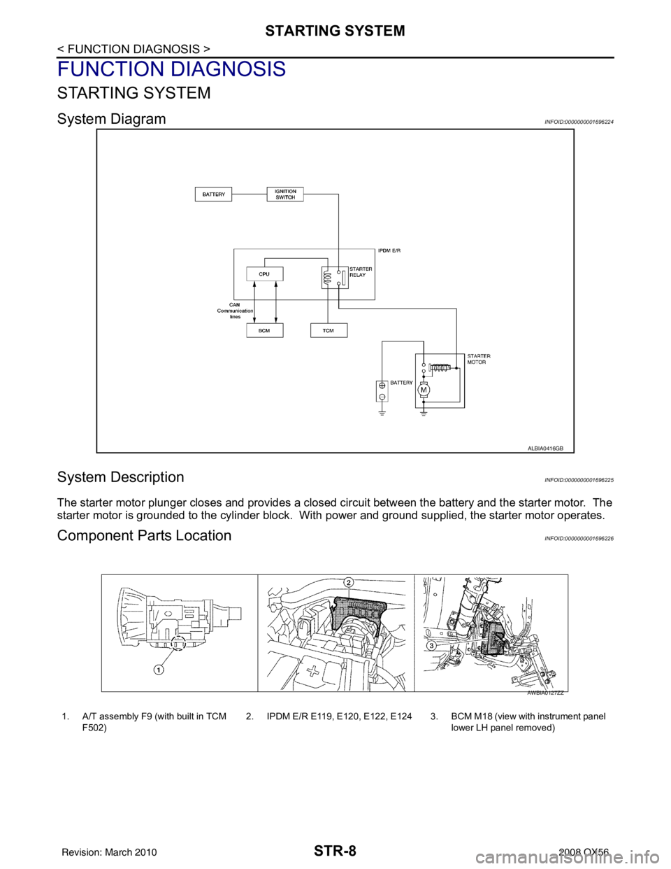
System DiagramINFOID:0000000001696224
System DescriptionINFOID:0000000001696225
The starter motor plunger closes and provides a closed circuit between the battery and the starter motor. The
starter motor is grounded to the cylinder block. With power and ground supplied, the starter motor operates.
Component Parts LocationINFOID:0000000001696226
ALBIA0416GB
1. A/T assembly F9 (with built in TCM
F502) 2. IPDM E/R E119, E120, E122, E124 3. BCM M18 (view with instrument panel
lower LH panel removed)
AWBIA0127ZZ
Revision: March 2010 2008 QX56
Page 3551 of 4083

TM-4
Precaution for Supplemental Restraint System
(SRS) "AIR BAG" and "SEAT BELT PRE-TEN-
SIONER" ................................................................
173
Precaution Necessary for Steering Wheel Rota-
tion After Battery Disconnect .................................
173
Precaution for On Board Diagnosis (OBD) System
of A/T and Engine ..................................................
174
Precaution .............................................................174
Service Notice or Precaution .................................175
PREPARATION ..........................................176
PREPARATION .............................................. .176
Special Service Tool ............................................ ..176
Commercial Service Tool ......................................177
ON-VEHICLE MAINTENANCE ..................178
A/T FLUID ....................................................... .178
Checking the A/T Fluid (ATF) .............................. ..178
Changing the A/T Fluid (ATF) ................................180
A/T FLUID COOLER ........................................182
A/T Fluid Cooler Cleaning ................................... ..182
Inspection ..............................................................184
STALL TEST ....................................................185
Inspection and Judgment .................................... ..185
LINE PRESSURE TEST ..................................187
Inspection and Judgment .................................... ..187
ROAD TEST .....................................................189
Description ........................................................... ..189
Check Before Engine Is Started ............................189
Check At Idle ....................................................... ..189
Cruise Test - Part 1 ...............................................190
Cruise Test - Part 2 ...............................................192
Cruise Test - Part 3 ...............................................193
Vehicle Speed When Shifting Gears .....................193
Vehicle Speed When Performing and Releasing
Complete Lock-up .................................................
193
A/T POSITION .................................................194
Checking of A/T Position ..................................... ..194
Adjustment of A/T Position ....................................194
ON-VEHICLE REPAIR ...............................195
SHIFT CONTROL SYSTEM ........................... .195
A/T Shift Selector Removal and Installation ..........195
Checking of A/T Position ..................................... ..196
Adjustment of A/T Position ....................................196
AIR BREATHER HOSE ...................................197
Removal and Installation ..................................... ..197
OIL PAN ...........................................................199
Oil Pan ................................................................. .199
CONTROL VALVE WITH TCM ........................201
Control Valve with TCM and A/T Fluid Tempera-
ture Sensor 2 ....................................................... .
201
REAR OIL SEAL ..............................................213
Rear Oil Seal ........................................................ .213
REMOVAL AND INSTALLATION .............214
TRANSMISSION ASSEMBLY ........................ ..214
Removal and Installation (2WD) .......................... .214
Removal and Installation (4WD) ...........................216
DISASSEMBLY AND ASSEMBLY ...........220
OVERHAUL ......................................................220
Component .......................................................... .220
Oil Channel ...........................................................227
Location of Adjusting Shims, Needle Bearings,
Thrust Washers and Snap Rings ......................... .
229
DISASSEMBLY .............................................. ..232
Disassembly ......................................................... .232
REPAIR FOR COMPONENT PARTS ..............250
Oil Pump .............................................................. .250
Front Sun Gear, 3rd One-Way Clutch ...................252
Front Carrier, Input Clutch, Rear Internal Gear .....254
Mid Sun Gear, Rear Sun Gear, High and Low Re-
verse Clutch Hub ................................................. .
259
High and Low Reverse Clutch ..............................264
Direct Clutch .........................................................266
ASSEMBLY .................................................... ..269
Assembly (1) ........................................................ .269
Adjustment ............................................................282
Assembly (2) .........................................................284
SERVICE DATA AND SPECIFICATIONS
(SDS) ........ .................................................
291
SERVICE DATA AND SPECIFICATIONS
(SDS) .............................................................. ..
291
General Specification ........................................... .291
Vehicle Speed at Which Gear Shifting Occurs .....291
Vehicle Speed at Which Lock-up Occurs/Releas-
es ......................................................................... .
291
Stall Speed ............................................................292
Line Pressure ........................................................292
A/T Fluid Temperature Sensor ..............................292
Input Speed Sensor ..............................................292
Output Speed Sensor ...........................................292
Reverse Brake ......................................................292
Total End Play .......................................................292
Torque Converter ..................................................293
Revision: March 2010 2008 QX56
Page 3958 of 4083

WT-12
< FUNCTION DIAGNOSIS >
DIAGNOSIS SYSTEM (BCM)
NOTE:
Before performing the self-diagnosis, be sure to register the ID, or the actual malfunction location may be different from that displayed on
CONSULT-III.
Self-Diagnosis (Without CONSULT-III)INFOID:0000000004291535
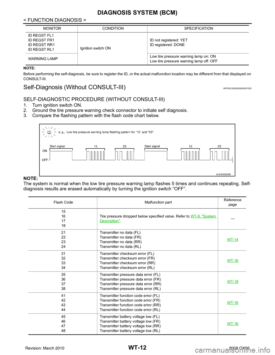
SELF-DIAGNOSTIC PROCEDURE (WITHOUT CONSULT-III)
1. Turn ignition switch ON.
2. Ground the tire pressure warning check connector to initiate self diagnosis.
3. Compare the flashing pattern with the flash code chart below.
NOTE:
The system is normal when the low tire pressure warning lamp flashes 5 times and continues repeating. Self-
diagnosis results are erased automatically by turning the ignition switch “OFF”.
ID REGST FL1
ID REGST FR1
ID REGST RR1
ID REGST RL1Ignition switch ON ID not registered: YET
ID registered: DONE
WARNING LAMP Low tire pressure
warning lamp on: ON
Low tire pressure warning lamp off: OFF
MONITOR
CONDITION SPECIFICATION
Flash Code Malfunction partReference
page
15
16
17
18 Tire pressure dropped below specified value. Refer to
WT-8, "
System
Description". —
21
22
23
24 Transmitter no data (FL)
Transmitter no data (FR)
Transmitter no data (RR)
Transmitter no data (RL)
WT-14
31
32
33
34Transmitter chec
ksum error (FL)
Transmitter chec ksum error (FR)
Transmitter chec ksum error (RR)
Transmitter chec ksum error (RL) WT-16
35
36
37
38Transmitter pressure
data error (FL)
Transmitter pressure data error (FR)
Transmitter pressure data error (RR)
Transmitter pressure data error (RL) WT-18
41
42
43
44Transmitter function
code error (FL)
Transmitter function code error (FR)
Transmitter function code error (RR)
Transmitter function code error (RL) WT-16
45
46
47
48Transmitter battery voltage low (FL)
Transmitter battery voltage low (FR)
Transmitter battery voltage low (RR)
Transmitter battery voltage low (RL)
WT-16
ALEIA0050GB
Revision: March 2010
2008 QX56
Page 3978 of 4083

WT-32
< ECU DIAGNOSIS >
BCM (BODY CONTROL MODULE)
NOTE:
Before performing the self-diagnosis, be sure to register the ID or else the actual malfunction location may be different from that dis-
played on CONSULT-III.
Self-Diagnosis (Without CONSULT-III)INFOID:0000000001735398
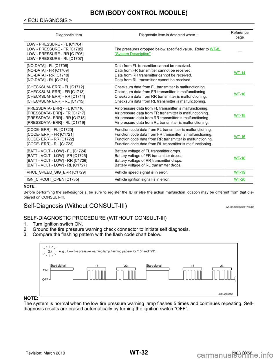
SELF-DIAGNOSTIC PROCEDURE (WITHOUT CONSULT-III)
1. Turn ignition switch ON.
2. Ground the tire pressure warning check connector to initiate self diagnosis.
3. Compare the flashing pattern with the flash code chart below.
NOTE:
The system is normal when the low tire pressure warning lamp flashes 5 times and continues repeating. Self-
diagnosis results are erased automatically by turning the ignition switch “OFF”.
Diagnostic item Diagnostic item is detected when ··· Reference
page
LOW - PRESSURE - FL [C1704]
LOW - PRESSURE - FR [C1705]
LOW - PRESSURE - RR [C1706]
LOW - PRESSURE - RL [C1707] Tire pressures dropped below specified value. Refer to WT-8,
"System Description".
—
[NO-DATA] - FL [C1708]
[NO-DATA] - FR [C1709]
[NO-DATA] - RR [C1710]
[NO-DATA] - RL [C1711] Data from FL transmitter cannot be received.
Data from FR transmitter cannot be received.
Data from RR transmitter cannot be received.
Data from RL transmitter cannot be received.
WT-14
[CHECKSUM- ERR] - FL [C1712]
[CHECKSUM- ERR] - FR [C1713]
[CHECKSUM- ERR] - RR [C1714]
[CHECKSUM- ERR] - RL [C1715]Checksum data from FL transmitter is malfunctioning.
Checksum data from FR transmitter is malfunctioning.
Checksum data from RR transmitter is malfunctioning.
Checksum data from RL transmitter is malfunctioning.
WT-16
[PRESSDATA- ERR] - FL [C1716]
[PRESSDATA- ERR] - FR [C1717]
[PRESSDATA- ERR] - RR [C1718]
[PRESSDATA- ERR] - RL [C1719]Air pressure data from FL transmitter is malfunctioning.
Air pressure data from FR transmitter is malfunctioning.
Air pressure data from RR transmitter is malfunctioning.
Air pressure data from RL transmitter is malfunctioning.
WT-18
[CODE- ERR] - FL [C1720]
[CODE- ERR] - FR [C1721]
[CODE- ERR] - RR [C1722]
[CODE- ERR] - RL [C1723]Function code data from FL transmitter is malfunctioning.
Function code data from FR transmitter is malfunctioning.
Function code data from RR transmitter is malfunctioning.
Function code data from RL transmitter is malfunctioning.
WT-16
[BATT - VOLT - LOW] - FL [C1724]
[BATT - VOLT - LOW] - FR [C1725]
[BATT - VOLT - LOW] - RR [C1726]
[BATT - VOLT - LOW] - RL [C1727]Battery voltage of FL transmitter drops.
Battery voltage of FR transmitter drops.
Battery voltage of RR transmitter drops.
Battery voltage of RL transmitter drops.
WT-16
VHCL_SPEED_SIG_ERR [C1729]
Vehicle speed signal is in error. WT-19
IGN_CIRCUIT_OPEN [C1735]Vehicle ignition signal is in error. WT-20
ALEIA0050GB
Revision: March 2010 2008 QX56