2008 INFINITI QX56 battery location
[x] Cancel search: battery locationPage 2659 of 4083
MWI-14
< FUNCTION DIAGNOSIS >
METER SYSTEM
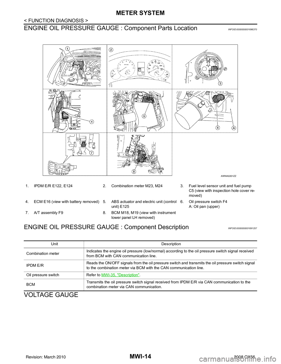
ENGINE OIL PRESSURE GAUGE : Component Parts Location
INFOID:0000000001696370
ENGINE OIL PRESSURE GAUGE : Component DescriptionINFOID:0000000001691257
VOLTAGE GAUGE
1. IPDM E/R E122, E124 2. Combination meter M23, M24 3. Fuel level sensor unit and fuel pump
C5 (view with inspection hole cover re-
moved)
4. ECM E16 (view with battery removed) 5. ABS actuator and electric unit (control
unit) E125 6. Oil pressure switch F4
A: Oil pan (upper)
7. A/T assembly F9 8. BCM M18, M19 (view with instrument
lower panel LH removed)
AWNIA0201ZZ
Unit Description
Combination meter Indicates the engine oil pressure (low/normal) according to the oil pressure switch signal received
from BCM with CAN
communication line.
IPDM E/R Reads the ON/OFF signals from the oil pressure switch and transmits the oil pressure switch signal
to the combination meter via BCM with the CAN communication line.
Oil pressure switch Refer to MWI-35, "
Description".
BCM Transmits the oil pressure switch signal received from IPDM E/R via CAN communication to the
combination meter via CAN communication.
Revision: March 2010
2008 QX56
Page 2660 of 4083
MWI
METER SYSTEMMWI-15
< FUNCTION DIAGNOSIS >
C
DE
F
G H
I
J
K L
M B A
O P
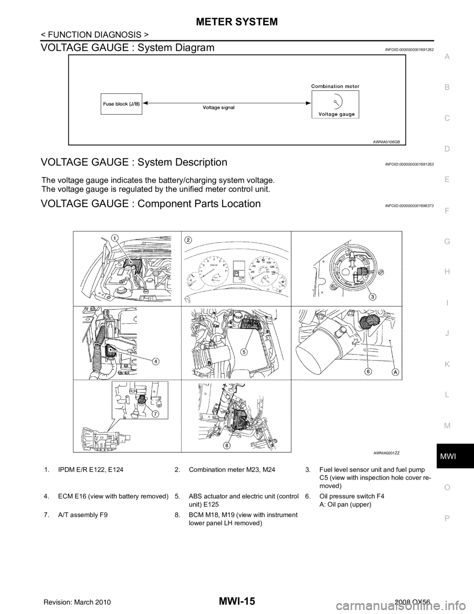
VOLTAGE GAUGE : System DiagramINFOID:0000000001691262
VOLTAGE GAUGE : System DescriptionINFOID:0000000001691263
The voltage gauge indicates the battery/charging system voltage.
The voltage gauge is regulated by the unified meter control unit.
VOLTAGE GAUGE : Component Parts LocationINFOID:0000000001696373
AWNIA0106GB
1. IPDM E/R E122, E124 2. Combination meter M23, M24 3. Fuel level sensor unit and fuel pump
C5 (view with inspection hole cover re-
moved)
4. ECM E16 (view with battery removed) 5. ABS actuator and electric unit (control unit) E1256. Oil pressure switch F4
A: Oil pan (upper)
7. A/T assembly F9 8. BCM M18, M19 (view with instrument
lower panel LH removed)
AWNIA0201ZZ
Revision: March 2010 2008 QX56
Page 2661 of 4083
MWI-16
< FUNCTION DIAGNOSIS >
METER SYSTEM
VOLTAGE GAUGE : Component Description
INFOID:0000000001691265
ODO/TRIP METER
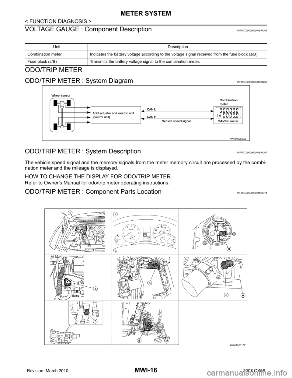
ODO/TRIP METER : System DiagramINFOID:0000000001691266
ODO/TRIP METER : System DescriptionINFOID:0000000001691267
The vehicle speed signal and the memory signals from the meter memory circuit are processed by the combi-
nation meter and the mileage is displayed.
HOW TO CHANGE THE DISPLAY FOR ODO/TRIP METER
Refer to Owner's Manual for odo/tr ip meter operating instructions.
ODO/TRIP METER : Component Parts LocationINFOID:0000000001696374
Unit Description
Combination meter Indicates the battery voltage according to the voltage signal received from the fuse block (J/B).
Fuse block (J/B) Transmits the battery voltage signal to the combination meter.
AWNIA0005GB
AWNIA0201ZZ
Revision: March 2010 2008 QX56
Page 2663 of 4083
MWI-18
< FUNCTION DIAGNOSIS >
METER SYSTEM
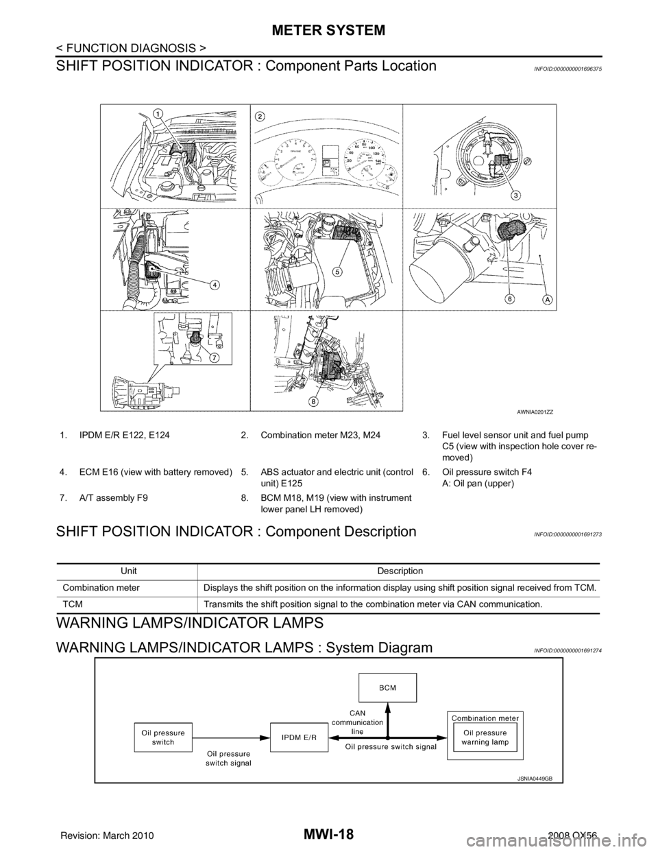
SHIFT POSITION INDICATOR : Component Parts Location
INFOID:0000000001696375
SHIFT POSITION INDICATOR : Component DescriptionINFOID:0000000001691273
WARNING LAMPS/INDICATOR LAMPS
WARNING LAMPS/INDICATOR LAMPS : System DiagramINFOID:0000000001691274
1. IPDM E/R E122, E124 2. Combination meter M23, M24 3. Fuel level sensor unit and fuel pump
C5 (view with inspection hole cover re-
moved)
4. ECM E16 (view with battery removed) 5. ABS actuator and electric unit (control
unit) E125 6. Oil pressure switch F4
A: Oil pan (upper)
7. A/T assembly F9 8. BCM M18, M19 (view with instrument
lower panel LH removed)
AWNIA0201ZZ
Unit Description
Combination meter Displays the shift position on the information display using shift position signal received from TCM.
TCM Transmits the shift position signal to the combination meter via CAN communication.
JSNIA0449GB
Revision: March 2010 2008 QX56
Page 2664 of 4083
MWI
METER SYSTEMMWI-19
< FUNCTION DIAGNOSIS >
C
DE
F
G H
I
J
K L
M B A
O P
WARNING LAMPS/INDICATOR LAMPS : System DescriptionINFOID:0000000001691275
OIL PRESSURE WARNING LAMP
• IPDM E/R reads the ON/OFF signals from the oil pressure switch and transmits the oil pressure switch sig-
nal to the combination meter via BCM with the CAN communication line.
• The combination meter turns the oil pressure warning lamp ON/OFF according to the oil pressure switch sig- nal received via CAN communication.
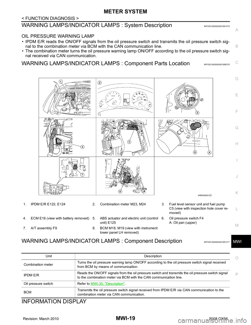
WARNING LAMPS/INDICATOR LAMPS : Component Parts LocationINFOID:0000000001696376
WARNING LAMPS/INDICATOR LAMPS : Component DescriptionINFOID:0000000001691277
INFORMATION DISPLAY
1. IPDM E/R E122, E124 2. Combination meter M23, M24 3. Fuel level sensor unit and fuel pump
C5 (view with inspection hole cover re-
moved)
4. ECM E16 (view with battery removed) 5. ABS actuator and electric unit (control unit) E1256. Oil pressure switch F4
A: Oil pan (upper)
7. A/T assembly F9 8. BCM M18, M19 (view with instrument
lower panel LH removed)
AWNIA0201ZZ
Unit Description
Combination meter Turns the oil pressure warning lamp ON/OFF according to the oil pressure switch signal received
from BCM by means of communication.
IPDM E/R Reads the ON/OFF signals from the oil pressure switch and transmits the oil pressure switch signal
to the combination meter via BCM with the CAN communication line.
Oil pressure switch Refer to MWI-35, "
Description".
BCM Transmits the oil pressure switch signal received from IPDM E/R via CAN communication to the
combination meter via CAN communication.
Revision: March 2010
2008 QX56
Page 2666 of 4083
MWI
METER SYSTEMMWI-21
< FUNCTION DIAGNOSIS >
C
DE
F
G H
I
J
K L
M B A
O P
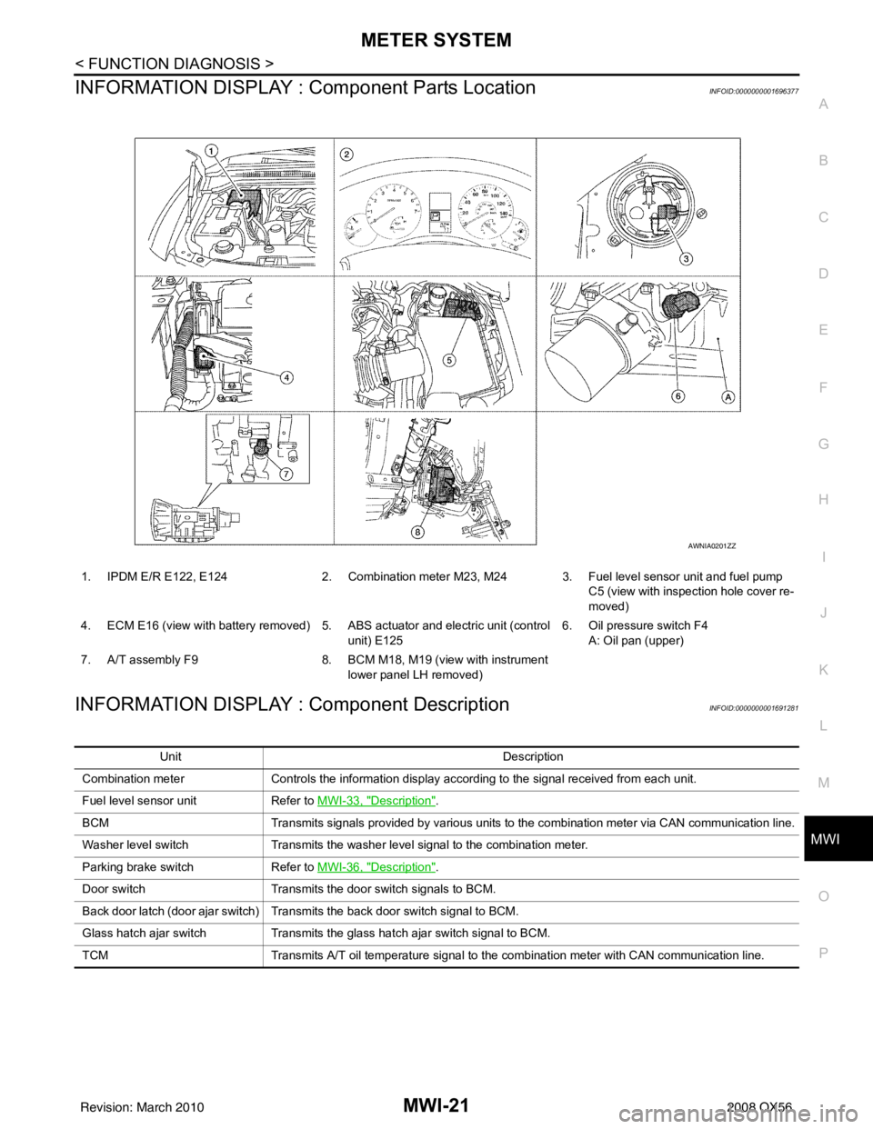
INFORMATION DISPLAY : Co mponent Parts LocationINFOID:0000000001696377
INFORMATION DISPLAY : Component DescriptionINFOID:0000000001691281
1. IPDM E/R E122, E124 2. Combination meter M23, M24 3. Fuel level sensor unit and fuel pump
C5 (view with inspection hole cover re-
moved)
4. ECM E16 (view with battery removed) 5. ABS actuator and electric unit (control unit) E1256. Oil pressure switch F4
A: Oil pan (upper)
7. A/T assembly F9 8. BCM M18, M19 (view with instrument
lower panel LH removed)
AWNIA0201ZZ
Unit Description
Combination meter Controls the information display according to the signal received from each unit.
Fuel level sensor unit Refer to MWI-33, "
Description".
BCM Transmits signals provided by various units to the combination meter via CAN communication line.
Washer level switch Transmits the washer level signal to the combination meter.
Parking brake switch Refer to MWI-36, "
Description".
Door switch Transmits the door switch signals to BCM.
Back door latch (door ajar switch) Transmits the back door switch signal to BCM.
Glass hatch ajar switch Transmits the glass hatch ajar switch signal to BCM.
TCM Transmits A/T oil temperature signal to the combination meter with CAN communication line.
Revision: March 2010 2008 QX56
Page 2734 of 4083
PCS
PCS-1
ELECTRICAL & POWER CONTROL
C
DE
F
G H
I
J
K L
B
SECTION PCS
A
O P
N
CONTENTS
POWER CONTROL SYSTEM
IPDM E/R
BASIC INSPECTION ....... .............................
2
DIAGNOSIS AND REPAIR WORKFLOW ..... .....2
Work Flow ........................................................... ......2
FUNCTION DIAGNOSIS ...............................5
RELAY CONTROL SYSTEM ......................... .....5
System Diagram .................................................. ......5
System Description ...................................................6
Component Parts Location ........................................7
POWER CONTROL SYSTEM .............................8
System Diagram .................................................. ......8
System Description ...................................................8
SIGNAL BUFFER SYSTEM ................................9
System Diagram .................................................. ......9
System Description ...................................................9
POWER CONSUMPTION CONTROL SYS-
TEM ....................................................................
10
System Diagram .................................................. ....10
System Description .................................................10
Component Parts Location ......................................11
DIAGNOSIS SYSTEM (IPDM E/R) .....................12
Diagnosis Description ......................................... ....12
CONSULT - III Function (IPDM E/R) .......................14
COMPONENT DIAGNOSIS .........................17
U1000 CAN COMM CIRCUIT ...........................17
Description ........................................................... ....17
DTC Logic ................................................................17
Diagnosis Procedure ...............................................17
POWER SUPPLY AND GROUND CIRCUIT ....18
Diagnosis Procedure ...............................................18
ECU DIAGNOSIS .........................................19
IPDM E/R (INTELLIGENT POWER DISTRI-
BUTION MODULE ENGINE ROOM) ................
19
Reference Value .................................................. ....19
Terminal Layout .......................................................21
Physical Values ................................................... ....21
Wiring Diagram ........................................................26
Fail Safe ..................................................................29
DTC Index ...............................................................31
PRECAUTION ..............................................32
PRECAUTIONS .................................................32
Precaution for Supplemental Restraint System
(SRS) "AIR BAG" and "SEAT BELT PRE-TEN-
SIONER" ............................................................. ....
32
Precaution Necessary for Steering Wheel Rota-
tion After Battery Disconnect ...................................
32
REMOVAL AND INSTALLATION ...............34
IPDM E/R (INTELLIGENT POWER DISTRI-
BUTION MODULE ENGINE ROOM) ................
34
Removal and Installation of IPDM E/R ................ ....34
Revision: March 2010 2008 QX56
Page 2768 of 4083

PG
PG-1
ELECTRICAL & POWER CONTROL
C
DE
F
G H
I
J
K L
B
SECTION PG
A
O P
N
CONTENTS
POWER SUPPLY, GROUND & CIRCUIT ELEMENTS
PRECAUTION .......
........................................2
PRECAUTIONS .............................................. .....2
Precaution for Supplemental Restraint System
(SRS) "AIR BAG" and "SEAT BELT PRE-TEN-
SIONER" ............................................................. ......
2
Precaution Necessary for Steering Wheel Rota-
tion After Battery Disconnect ............................... ......
2
Precaution for Power Generation Variable Voltage
Control System ..........................................................
3
PREPARATION ............................................4
PREPARATION .............................................. .....4
Special Service Tool ........................................... ......4
Commercial Service Tool ..........................................4
BASIC INSPECTION ....................................5
BATTERY ....................................................... .....5
How to Handle Battery ........................................ ......5
Work Flow ........................................................... ......7
INSPECTION AND ADJUSTMENT .....................8
ADDITIONAL SERVICE WHEN REMOVING BAT-
TERY NEGATIVE TERMINAL ............................... ......
8
ADDITIONAL SERVICE WHEN REMOVING
BATTERY NEGATIVE TERMINAL : Special Re-
pair Requirement ................................................. ......
8
COMPONENT DIAGNOSIS ..........................9
POWER SUPPLY ROUTING CIRCUIT .......... .....9
Wiring Diagram — Battery Power Supply — ....... ......9
Wiring Diagram — Accessory Power Supply — .....17
Wiring Diagram — Ignition Power Supply — ....... ....21
Fuse .........................................................................29
Fusible Link .............................................................29
GROUND ...........................................................30
Ground Distribution ..................................................30
HARNESS .........................................................40
Harness Layout ................................................... ....40
ELECTRICAL UNITS LOCATION ....................62
Electrical Units Location ..........................................62
HARNESS CONNECTOR .................................65
Description ...............................................................65
STANDARDIZED RELAY .................................68
Description ...............................................................68
FUSE BLOCK - JUNCTION BOX (J/B) ............70
Terminal Arrangement .............................................70
FUSE, FUSIBLE LINK AND RELAY BOX ........71
Terminal Arrangement .............................................71
ON-VEHICLE REPAIR .................................73
BATTERY ..........................................................73
Removal and Installation ..................................... ....73
SERVICE DATA AND SPECIFICATIONS
(SDS) ............... .......................................... ...
74
SERVICE DATA AND SPECIFICATIONS
(SDS) .................................................................
74
Battery ................................................................. ....74
Revision: March 2010 2008 QX56