2008 INFINITI QX56 battery location
[x] Cancel search: battery locationPage 2384 of 4083

INL-1
DRIVER CONTROLS
C
DE
F
G H
I
J
K
M
SECTION INL
A
B
INL
N
O P
CONTENTS
INTERIOR LIGHTING SYSTEM
BASIC INSPECTION ....... .............................3
DIAGNOSIS AND REPAIR WORKFLOW ..... .....3
Work Flow ........................................................... ......3
FUNCTION DIAGNOSIS ...............................6
INTERIOR ROOM LAMP CONTROL SYSTEM
.....
6
System Diagram .................................................. ......6
System Description ...................................................6
Component Parts Location ........................................7
Component Description .............................................8
ILLUMINATION CONTROL SYSTEM .................9
System Diagram .................................................. ......9
System Description ...................................................9
Component Parts Location ........................................9
Component Description ...........................................10
DIAGNOSIS SYSTEM (BCM) ............................11
COMMON ITEM ..................................................... ....11
COMMON ITEM : CONSULT-III Function ...............11
INT LAMP .............................................................. ....11
INT LAMP : CONSULT-III Function ........................11
BATTERY SAVER ................................................. ....13
BATTERY SAVER : CONSULT-III Function ...........13
COMPONENT DIAGNOSIS .........................14
POWER SUPPLY AND GROUND CIRCUIT .. ....14
BCM ....................................................................... ....14
BCM : Inspection Procedure ...................................14
INTERIOR ROOM LAMP POWER SUPPLY
CIRCUIT ......................................................... ....
15
Description .......................................................... ....15
Component Function Check ....................................15
Diagnosis Procedure ...............................................15
INTERIOR ROOM LAMP CONTROL CIRCUIT
...
17
Description ........................................................... ....17
Component Function Check ....................................17
Diagnosis Procedure ...............................................17
STEP LAMP CIRCUIT .......................................19
Description ........................................................... ....19
Component Function Check ....................................19
Diagnosis Procedure ...............................................19
CARGO LAMP CONTROL CIRCUIT ................21
Description ...............................................................21
Component Function Check ....................................21
Diagnosis Procedure ...............................................21
IGNITION KEYHOLE ILLUMINATION CON-
TROL CIRCUIT .................................................
23
Description ...............................................................23
Component Function Check ....................................23
Diagnosis Procedure ...............................................23
INTERIOR ROOM LAMP CONTROL SYSTEM
...
25
Wiring Diagram .................................................... ....25
ILLUMINATION .................................................41
Wiring Diagram ........................................................41
ECU DIAGNOSIS .........................................55
BCM (BODY CONTROL MODULE) .................55
Description ........................................................... ....55
SYMPTOM DIAGNOSIS ..............................56
INTERIOR LIGHTING SYSTEM SYMPTOMS ...56
Symptom Table ................................................... ....56
PRECAUTION ..............................................57
PRECAUTIONS .................................................57
Revision: March 2010 2008 QX56
Page 2390 of 4083
INTERIOR ROOM LAMP CONTROL SYSTEMINL-7
< FUNCTION DIAGNOSIS >
C
DE
F
G H
I
J
K
M A
B
INL
N
O P
INTERIOR LAMP BATTERY SAVER CONTROL
If an interior lamp is left ON and does not turn OFF even when the doors are closed, the BCM turns off power
to the interior lamps automatically to save the batte ry 30 minutes after the ignition switch is turned OFF.
The BCM controls power and ground to all interior lamps.
After the battery saver system turns the la mps OFF, the lamps will illuminate again when
• a signal is received from an Intelligent Key or main power window and door lock/unlock switch, or when the
front door LH lock assembly (key cylinder switch) is locked or unlocked
• a door is opened or closed
• the Intelligent Key is removed from or inserted into the ignition switch.
The Interior lamp battery saver control time peri od can be changed with the function setting of CONSULT-III.
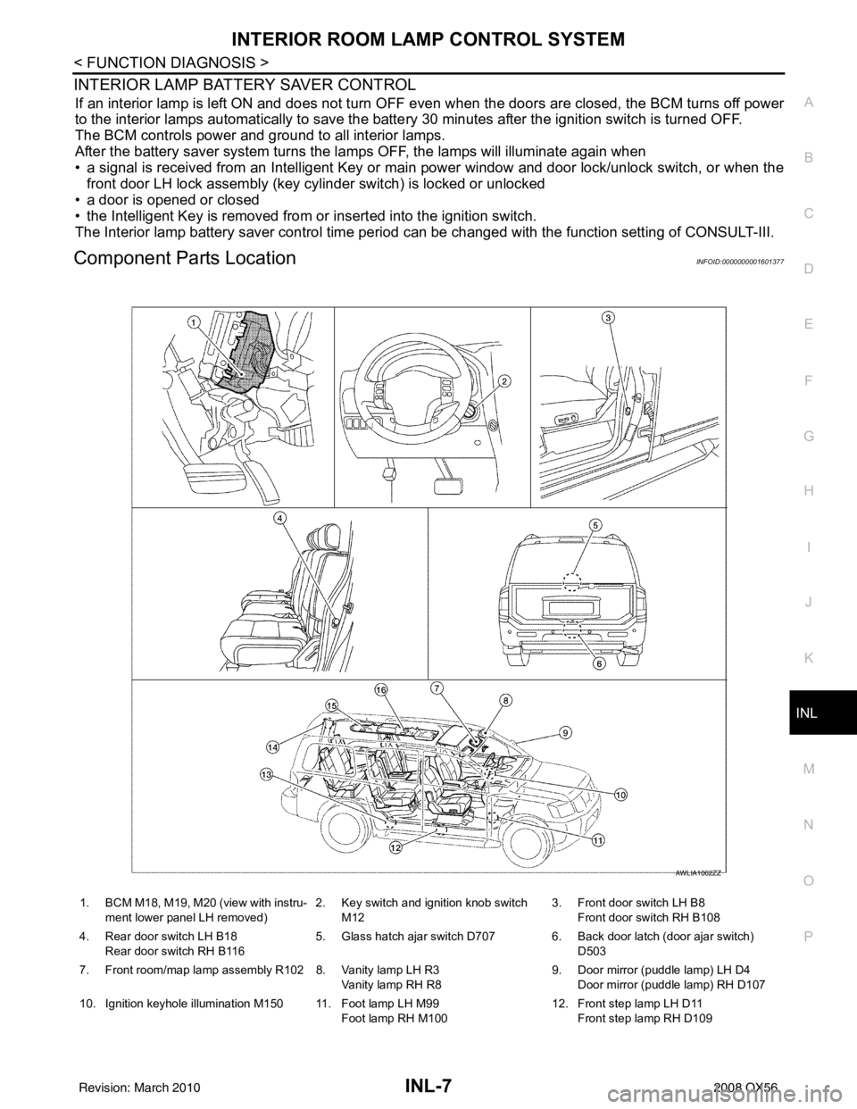
Component Parts LocationINFOID:0000000001601377
1. BCM M18, M19, M20 (view with instru-
ment lower panel LH removed) 2. Key switch and ignition knob switch
M12 3. Front door switch LH B8
Front door switch RH B108
4. Rear door switch LH B18 Rear door switch RH B116 5. Glass hatch ajar switch D707 6. Back door latch (door ajar switch)
D503
7. Front room/map lamp assembly R102 8. Vanity lamp LH R3 Vanity lamp RH R89. Door mirror (puddle lamp) LH D4
Door mirror (puddle lamp) RH D107
10. Ignition keyhole illumination M150 11. Foot lamp LH M99 Foot lamp RH M10012. Front step lamp LH D11
Front step lamp RH D109
AWLIA1062ZZ
Revision: March 2010 2008 QX56
Page 2392 of 4083
ILLUMINATION CONTROL SYSTEMINL-9
< FUNCTION DIAGNOSIS >
C
DE
F
G H
I
J
K
M A
B
INL
N
O P
ILLUMINATION CONTROL SYSTEM
System DiagramINFOID:0000000001601379
System DescriptionINFOID:0000000001601380
The illumination lamps operation is dependent upon the posit ion of the lighting switch (combination switch).
When the lighting switch is placed in the 1ST or 2ND posit ion (or if the auto light system is activated) the BCM
(body control module) receives input requesting the park ing lamps to illuminate. This input is communicated to
the IPDM E/R (intelligent power distribution module engine room) via the CAN communication lines. The CPU
(central processing unit) of the IPDM E/R controls the tail lamp relay coil. When energized, this relay directs
power to the parking and illumination lamps, which then illuminate.
BATTERY SAVER CONTROL
When the lighting switch (combination switch) is in t he 1ST or 2ND position and the ignition switch is turned
from ON or ACC to OFF, the battery saver control feat ure is activated. Under this condition, the illumination
lamps remain illuminated for 30 minutes unless the light ing switch position is changed. If the lighting switch
position is changed, then the illumination lamps are turned off after a 30 second delay. When the lighting
switch is turned from OFF to 1ST or 2ND position (or if auto light system is activated) after illumination lamps
have been turned off by the battery saver control, the illumination lamps illuminate again.
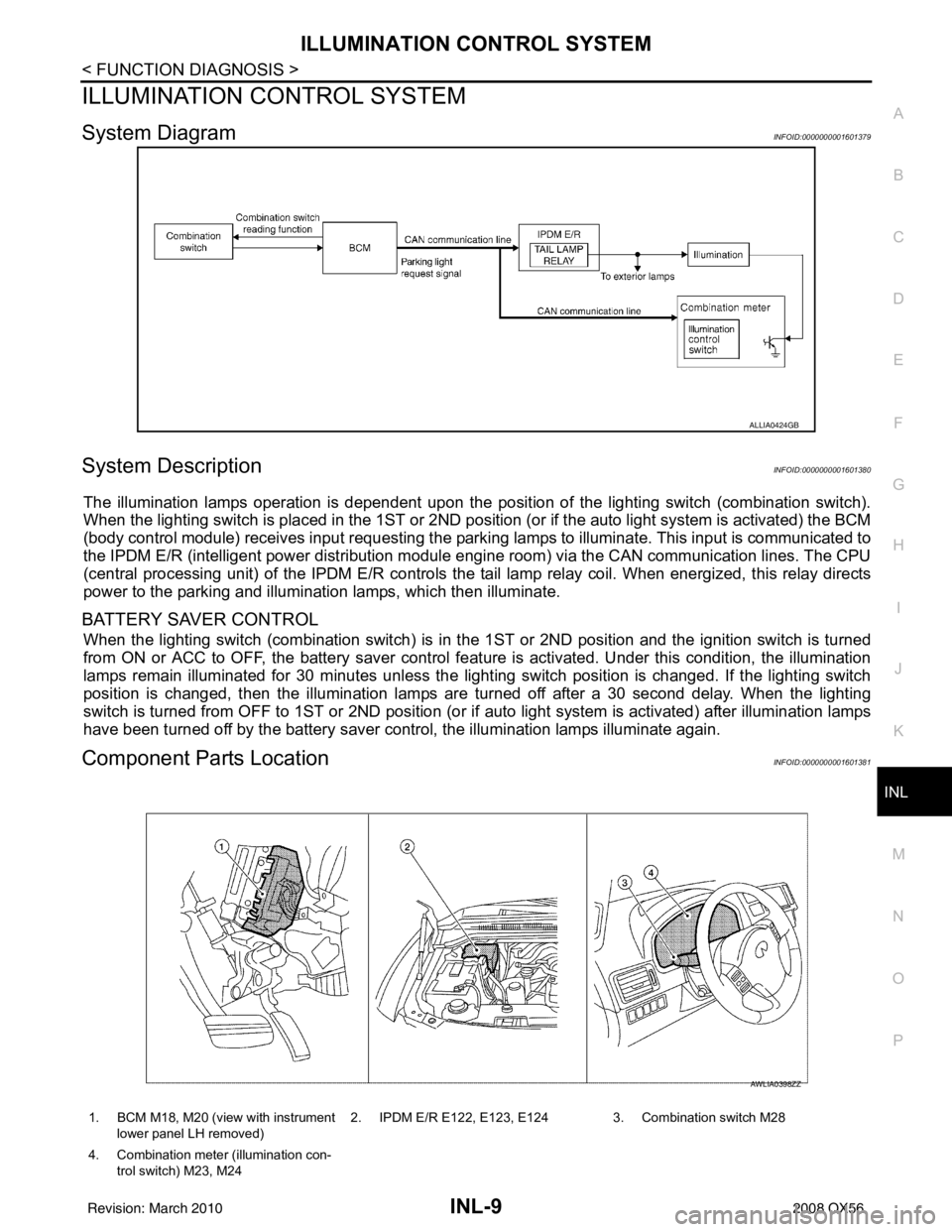
Component Parts LocationINFOID:0000000001601381
ALLIA0424GB
1. BCM M18, M20 (view with instrument
lower panel LH removed) 2. IPDM E/R E122, E123, E124 3. Combination switch M28
4. Combination meter (illumination con- trol switch) M23, M24
AWLIA0398ZZ
Revision: March 2010 2008 QX56
Page 2584 of 4083
PRECAUTIONSLU-3
< PRECAUTION >
C
DE
F
G H
I
J
K L
M A
LU
NP
O
5. When the repair work is completed, return the ignition switch to the
″LOCK ″ position before connecting
the battery cables. (At this time, the steering lock mechanism will engage.)
6. Perform a self-diagnosis check of al l control units using CONSULT-III.
Precaution for Liquid GasketINFOID:0000000001538839
REMOVAL OF LIQUID GASKET SEALING
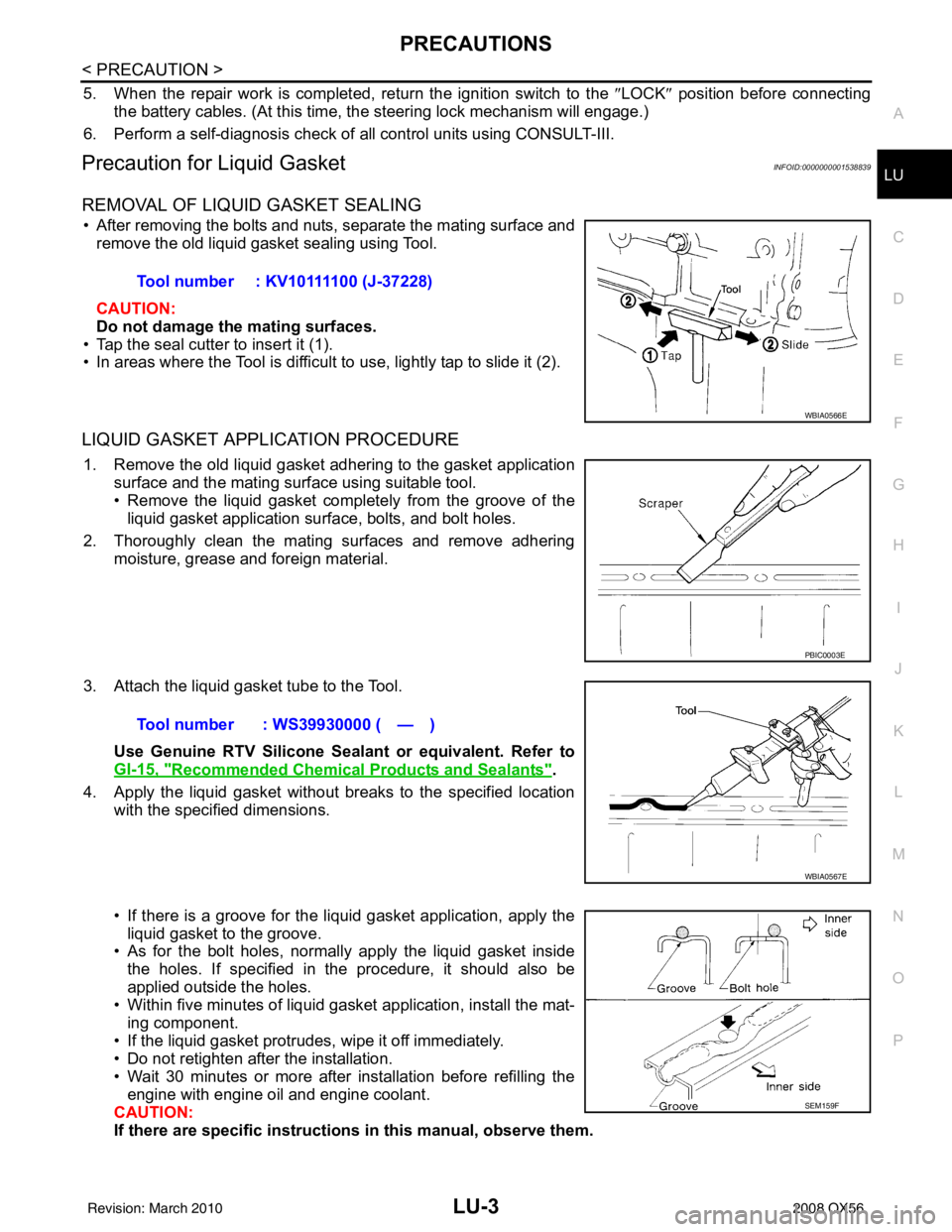
• After removing the bolts and nuts, separate the mating surface and
remove the old liquid gasket sealing using Tool.
CAUTION:
Do not damage the mating surfaces.
• Tap the seal cutter to insert it (1).
• In areas where the Tool is difficult to use, lightly tap to slide it (2).
LIQUID GASKET APPLICATION PROCEDURE
1. Remove the old liquid gasket adhering to the gasket application surface and the mating surface using suitable tool.
• Remove the liquid gasket completely from the groove of the
liquid gasket application surface, bolts, and bolt holes.
2. Thoroughly clean the mating surfaces and remove adhering moisture, grease and foreign material.
3. Attach the liquid gasket tube to the Tool. Use Genuine RTV Silicone Sealant or equivalent. Refer to
GI-15, "
Recommended Chemical Products and Sealants".
4. Apply the liquid gasket without breaks to the specified location with the specified dimensions.
• If there is a groove for the liquid gasket application, apply theliquid gasket to the groove.
• As for the bolt holes, normally apply the liquid gasket inside
the holes. If specified in the procedure, it should also be
applied outside the holes.
• Within five minutes of liquid gasket application, install the mat-
ing component.
• If the liquid gasket protrudes, wipe it off immediately.
• Do not retighten after the installation.
• Wait 30 minutes or more after installation before refilling the engine with engine oil and engine coolant.
CAUTION:
If there are specific instructions in this manual, observe them.
Tool number : KV10111100 (J-37228)
WBIA0566E
PBIC0003E
Tool number : WS39930000 ( — )
WBIA0567E
SEM159F
Revision: March 2010
2008 QX56
Page 2652 of 4083
MWI
METER SYSTEMMWI-7
< FUNCTION DIAGNOSIS >
C
DE
F
G H
I
J
K L
M B A
O P
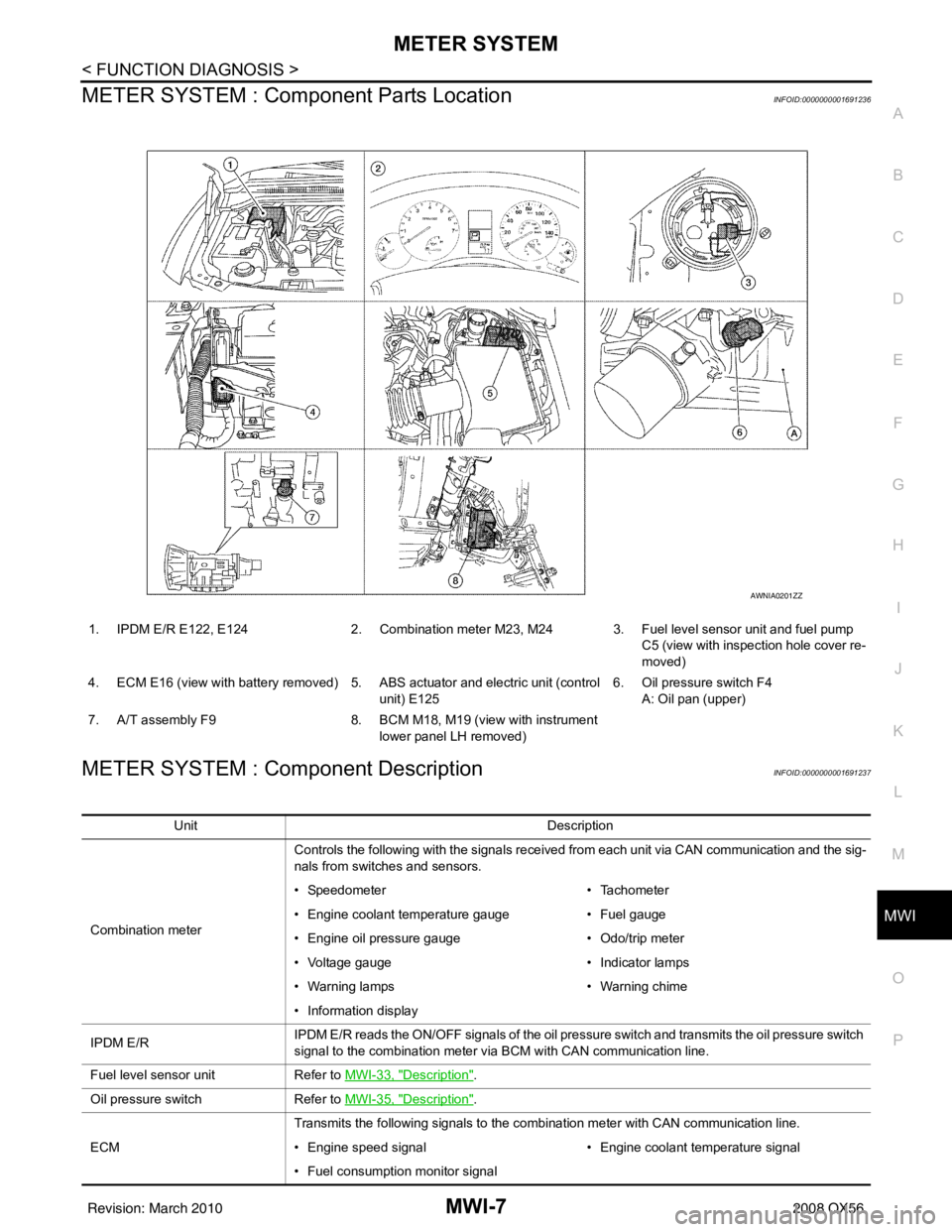
METER SYSTEM : Com ponent Parts LocationINFOID:0000000001691236
METER SYSTEM : Component DescriptionINFOID:0000000001691237
1. IPDM E/R E122, E124 2. Combination meter M23, M24 3. Fuel level sensor unit and fuel pump
C5 (view with inspection hole cover re-
moved)
4. ECM E16 (view with battery removed) 5. ABS actuator and electric unit (control unit) E1256. Oil pressure switch F4
A: Oil pan (upper)
7. A/T assembly F9 8. BCM M18, M19 (view with instrument
lower panel LH removed)
AWNIA0201ZZ
Unit Description
Combination meter Controls the following with the signals received from each unit via CAN communication and the sig-
nals from switches and sensors.
• Speedometer
• Tachometer
• Engine coolant temperature gauge • Fuel gauge
• Engine oil pressure gauge • Odo/trip meter
• Voltage gauge • Indicator lamps
• Warning lamps • Warning chime
• Information display
IPDM E/R IPDM E/R reads the ON/OFF signals of the oil pressure switch and transmits the oil pressure switch
signal to the combination meter via BCM with CAN communication line.
Fuel level sensor unit Refer to MWI-33, "
Description".
Oil pressure switch Refer to MWI-35, "
Description".
ECM Transmits the following signals to the combination meter with CAN communication line.
• Engine speed signal
• Engine coolant temperature signal
• Fuel consumption monitor signal
Revision: March 2010 2008 QX56
Page 2654 of 4083
MWI
METER SYSTEMMWI-9
< FUNCTION DIAGNOSIS >
C
DE
F
G H
I
J
K L
M B A
O P
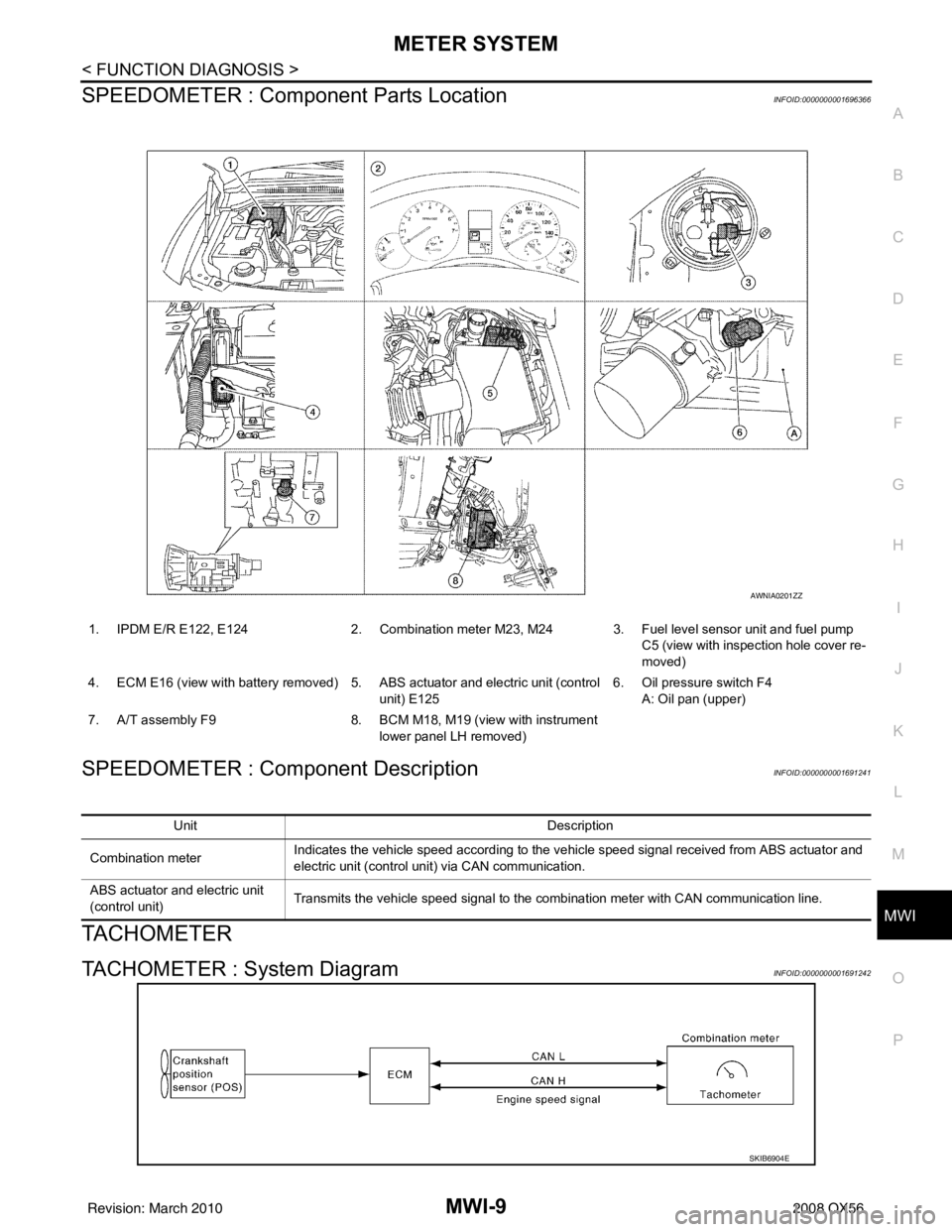
SPEEDOMETER : Compone nt Parts LocationINFOID:0000000001696366
SPEEDOMETER : Component DescriptionINFOID:0000000001691241
TACHOMETER
TACHOMETER : System DiagramINFOID:0000000001691242
1. IPDM E/R E122, E124 2. Combination meter M23, M24 3. Fuel level sensor unit and fuel pump
C5 (view with inspection hole cover re-
moved)
4. ECM E16 (view with battery removed) 5. ABS actuator and electric unit (control unit) E1256. Oil pressure switch F4
A: Oil pan (upper)
7. A/T assembly F9 8. BCM M18, M19 (view with instrument
lower panel LH removed)
AWNIA0201ZZ
Unit Description
Combination meter Indicates the vehicle speed according to the vehicle speed signal received from ABS actuator and
electric unit (control unit) via CAN communication.
ABS actuator and electric unit
(control unit) Transmits the vehicle speed signal to the combination meter with CAN communication line.
SKIB6904E
Revision: March 2010
2008 QX56
Page 2655 of 4083
MWI-10
< FUNCTION DIAGNOSIS >
METER SYSTEM
TACHOMETER : System Description
INFOID:0000000001691243
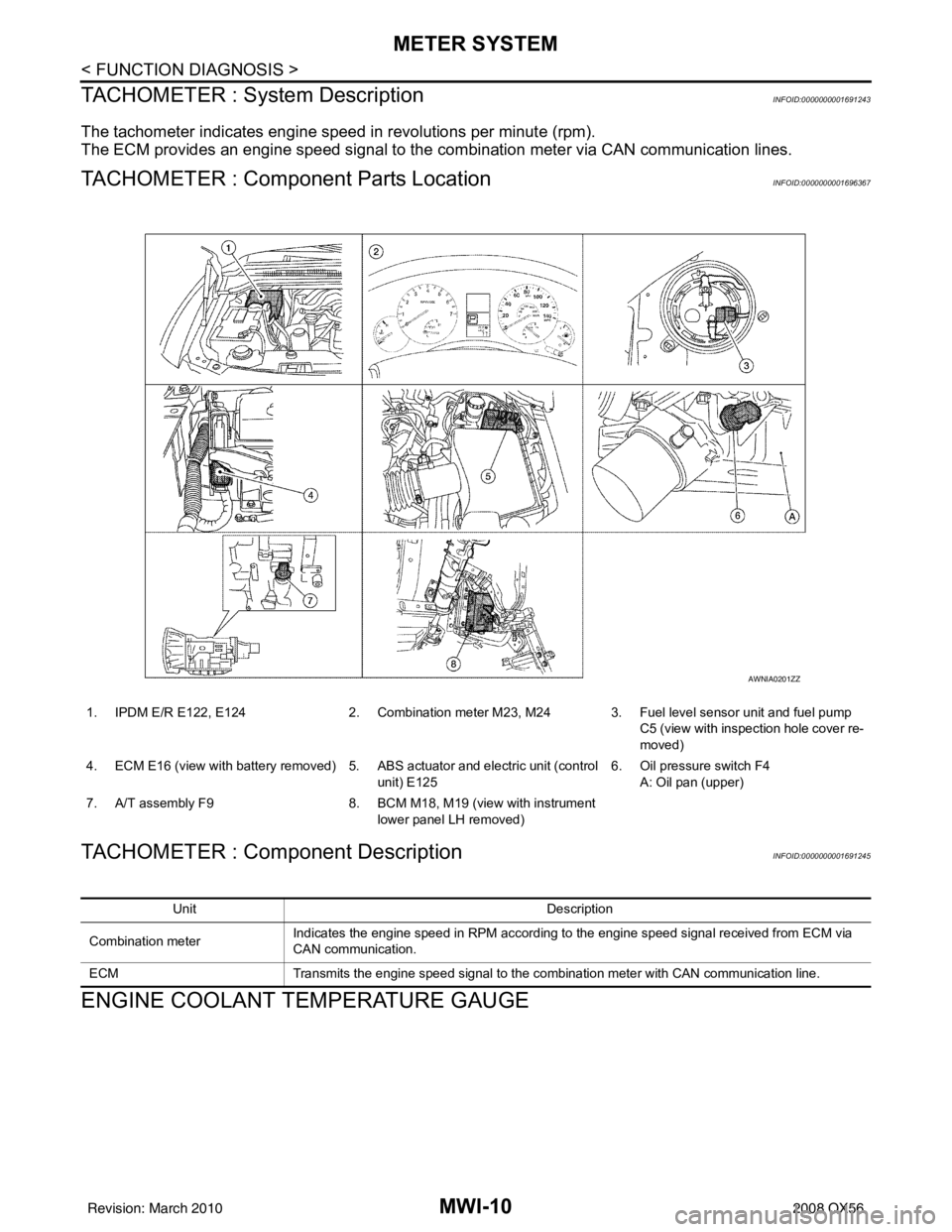
The tachometer indicates engine speed in revolutions per minute (rpm).
The ECM provides an engine speed signal to the co mbination meter via CAN communication lines.
TACHOMETER : Component Parts LocationINFOID:0000000001696367
TACHOMETER : Component DescriptionINFOID:0000000001691245
ENGINE COOLANT TEMPERATURE GAUGE
1. IPDM E/R E122, E1242. Combination meter M23, M24 3. Fuel level sensor unit and fuel pump
C5 (view with inspection hole cover re-
moved)
4. ECM E16 (view with battery removed) 5. ABS actuator and electric unit (control
unit) E125 6. Oil pressure switch F4
A: Oil pan (upper)
7. A/T assembly F9 8. BCM M18, M19 (view with instrument
lower panel LH removed)
AWNIA0201ZZ
Unit Description
Combination meter Indicates the engine speed in RPM according to the engine speed signal received from ECM via
CAN communication.
ECM Transmits the engine speed signal to the combination meter with CAN communication line.
Revision: March 2010 2008 QX56
Page 2656 of 4083
MWI
METER SYSTEMMWI-11
< FUNCTION DIAGNOSIS >
C
DE
F
G H
I
J
K L
M B A
O P
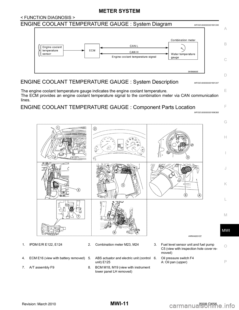
ENGINE COOLANT TEMPERATURE GAUGE : System DiagramINFOID:0000000001691246
ENGINE COOLANT TEMPERATURE GAUGE : System DescriptionINFOID:0000000001691247
The engine coolant temperature gauge indicates the engine coolant temperature.
The ECM provides an engine coolant temperature signal to the combination meter via CAN communication
lines.
ENGINE COOLANT TEMPERATURE GA UGE : Component Parts Location
INFOID:0000000001696368
SKIB6905E
1. IPDM E/R E122, E124 2. Combination meter M23, M24 3. Fuel level sensor unit and fuel pump
C5 (view with inspection hole cover re-
moved)
4. ECM E16 (view with battery removed) 5. ABS actuator and electric unit (control unit) E1256. Oil pressure switch F4
A: Oil pan (upper)
7. A/T assembly F9 8. BCM M18, M19 (view with instrument
lower panel LH removed)
AWNIA0201ZZ
Revision: March 2010 2008 QX56