2008 INFINITI QX56 seat memory
[x] Cancel search: seat memoryPage 169 of 4083

ADP SYSTEM SYMPTOMSADP-155
< SYMPTOM DIAGNOSIS >
C
DE
F
G H
I
K L
M A
B
ADP
N
O P
SYMPTOM DIAGNOSIS
ADP SYSTEM SYMPTOMS
Symptom TableINFOID:0000000001735561
NOTE:
Always perform the “Basic Inspection” before perfo rming diagnosis in the following table. Refer to ADP-5,
"Work Flow".
SYMPTOM 1
SYMPTOM 2
SYMPTOM 3
Symptom Diagnosis procedureReference
page
Manual functions (for specific part) do
not operate Sliding operation
Check sliding switch. ADP-46
Reclining operationCheck reclining switch. ADP-48
Lifting operation (front) Check lifting switch (front). ADP-50
Lifting operation (rear) Check lifting switch (rear).ADP-52
Pedal operation1. Check pedal adjusting switch.
ADP-562. Check pedal adjusting sensor.ADP-81
Steering wheel tilt operation Check ADP steering switch ADP-54
Door mirror operation1. Changeover switch.
ADP-612. Mirror switchADP-63
All parts of seatCheck power seat switch ground cir-
cuit. ADP-66
Symptom
Diagnosis procedureReference
page
Memory functions (for specific part) do
not operate Sliding operation
Check sliding sensor. ADP-71
Reclining operationCheck reclining sensor. ADP-73
Lifting operation (front) Check lifting sensor (front). ADP-75
Lifting operation (rear) Check lifting sensor (rear).ADP-77
Pedal operationCheck pedal adjusting sensor. ADP-81
Steering wheel tilt operation Check tilt sensor ADP-79
Door mirror operation Check door mirror sensor. Driver side:
ADP-83Passenger side:
ADP-85
Symptom Diagnosis procedureReference
page
Memory functions and manual func-
tions (for specific part) do not operate Sliding operation
Check sliding motor. ADP-87
Reclining operationCheck reclining motor. ADP-89
Lifting operation (front) Check lifting motor (front). ADP-91
Lifting operation (rear) Check lifting motor (rear).ADP-93
Pedal operationCheck pedal adjusting motor. ADP-97
Steering wheel operation Check tilt motor ADP-95
Door mirror operation Check door mirror motor.ADP-99
Revision: March 2010 2008 QX56
Page 170 of 4083

ADP-156
< SYMPTOM DIAGNOSIS >
ADP SYSTEM SYMPTOMS
SYMPTOM 4
SYMPTOM 5
SYMPTOM 6
SymptomDiagnosis procedureReference
page
Entry/Exit assist function does not operate. 1. Check system setting.
ADP-20
2. Perform initialization.ADP-22
3. Check front door switch (driver side).ADP-69
SymptomDiagnosis procedureReference
page
Memory indicators 1 and/or 2 do not illuminate. 1. Check seat memory switch.
ADP-59
2. Check seat memory indicator.ADP-102
SymptomDiagnosis procedureReference
page
Memory operation does not operate. Check A/T shift selector (park position switch). ADP-67
Revision: March 2010 2008 QX56
Page 171 of 4083

NORMAL OPERATING CONDITIONADP-157
< SYMPTOM DIAGNOSIS >
C
DE
F
G H
I
K L
M A
B
ADP
N
O P
NORMAL OPERATING CONDITION
DescriptionINFOID:0000000001735562
The following symptoms are normal operations, and they do not indicate a malfunction.
Symptom CauseAction to take Reference page
Entry/Exit assist function does
not operate. No initialization has been performed. Perform initialization.
ADP-20
Entry/exit assist function is disabled.
NOTE:
The entry/exit assist function is disabled
before delivery (initial setting).Change the settings.
ADP-23
Entry assist function does not op-
erate. Manual operation with power seat switch
was performed after exit assist function
excution. Perform the memory
function. ADP-23
Memory function, entry/exit as-
sist function or Intelligent Key in-
terlock function does not
operate. The operating conditions are not fulfilled.
Fulfill the operation
conditions. Memory function:
ADP-17Exit assist function: ADP-20
Entry assist function: ADP-23
Intelligent Key interlock
function: ADP-10
Revision: March 2010 2008 QX56
Page 174 of 4083

ADP-160
< ON-VEHICLE MAINTENANCE >
PRE-INSPECTION FOR DIAGNOSTIC
ON-VEHICLE MAINTENANCE
PRE-INSPECTION FOR DIAGNOSTIC
Basic InspectionINFOID:0000000001735563
1. CHECK POWER SUPPLY AND DROUND CIRCUIT
Check the power supply and ground circuit as shown below.
• Driver seat control unit :Refer to ADP-44, "
DRIVER SEAT CONTROL UNIT : DiagnosisProcedure".
• Automatic drive positioner control unit: Refer to ADP-45, "
AUTOMATIC DRIVE POSITIONER CONTROL
UNIT : DiagnosisProcedure".
Is the inspection result normally?
YES >> GO TO 2
NO >> Repair or replace the malfunctioning part.
2. CHECK MANUAL FUNCTION
Check the manual function operations by operati ng the relevant switches as shown below.
• Seat (slide, reclining, lifting front, lifting rear)
• Pedal assembly (forward, backward)
• Steering wheel (upward, downward)
• Door mirror
Do all manual functions operate normally?
YES >> GO TO 3
NO (Seat, pedal, door mirror)>>Go to SYMPTOM 1, refer to ADP-155, "
Symptom Table". And, GO TO 4 if
the result of SYMPTOM 1 is OK.
3. CHECK MEMORY FUNCTION 1
Register the seat positions (refer to Owner’s Manual) and check that all parts of the seat, pedals, steering
wheel and door mirrors move to their memory positions correctly.
Are the operations normal?
YES >> Check each malfunction according to the instruction of the SYMPTOM 4, refer to ADP-155,
"Symptom Table".
No (memory indicator operates normally)>> Go to SYMPTOM 2, refer to ADP-155, "
Symptom Table".
No (memory indicator does not operate normally either)>> GO TO 5
4. CHECK MEMORY FUNCTION 2
Register the seat positions (refer to Owner’s Manual) and check that all parts of the seat, pedals, steering
wheel and door mirrors move to their memory positions correctly.
Are the operations normal?
YES >> Check intermittent incident. Refer to GI-38, "Intermittent Incident".
NO >> GO TO 7
5. CHECK SEAT MEMORY SWITCH/MEMORY INDICATOR
Check the seat memory switch/memory switch indicator of the SYMPTOM 5, refer to ADP-155, "
Symptom
Table".
Is the inspection result normal?
YES >> GO TO 6
NO >> Repair or replace the malfunctioning part.
6. CHECK OPERATION CONDITION
Check the memory operation conditions (refer to ADP-10, "
AUTOMATIC DRIVE POSITIONER SYSTEM :
System Description").
Are all operation conditions fulfilled?
YES >> Go to SYMPTOM 6, refer to ADP-155, "Symptom Table".
NO >> Fulfill the operation conditions. Refer to ADP-10, "
AUTOMATIC DRIVE POSITIONER SYSTEM :
System Description".
Revision: March 2010 2008 QX56
Page 2255 of 4083

HAC-2
MAGNET CLUTCH ............................................71
System Description .............................................. ...71
Magnet Clutch Component Function Check ........ ...71
Magnet Clutch Diagnosis Procedure ................... ...72
WATER VALVE CIRCUIT ..................................76
Description ........................................................... ...76
Water Valve Diagnosis Procedure ..........................76
AMBIENT SENSOR ...........................................78
Component Description ....................................... ...78
Ambient Sensor Diagnosis Procedure ....................78
Ambient Sensor Component Inspection .................79
IN-VEHICLE SENSOR .......................................81
Component Description ....................................... ...81
In-Vehicle Sensor Diagnosis Procedure .................81
In-Vehicle Sensor Component Inspection ..............83
OPTICAL SENSOR ...........................................84
Component Description ..........................................84
Optical Sensor Diagnosis Procedure ......................84
INTAKE SENSOR ..............................................86
System Description .............................................. ...86
Intake Sensor Diagnosis Procedure .......................86
Intake Sensor Component Inspection ................. ...87
POWER SUPPLY AND GROUND CIRCUIT
FOR CONTROLLER ..........................................
88
Component Description ....................................... ...88
A/C Auto Amp. Component Function Check ..........88
A/C Auto Amp Power and Ground Diagnosis Pro-
cedure .....................................................................
89
ECU DIAGNOSIS .......................................90
AIR CONDITIONER CONTROL ..................... ...90
A/C Auto Amp. Terminals Reference Values ..........90
Wiring Diagram .................................................... ...92
SYMPTOM DIAGNOSIS ...........................108
AIR CONDITIONER CONTROL ..................... ..108
Symptom Matrix Chart ........................................ .108
INSUFFICIENT COOLING ................................109
Component Function Check ................................ .109
Diagnostic Work Flow ...........................................110
Performance Chart ................................................113
Trouble Diagnoses for Abnormal Pressure ...........114
INSUFFICIENT HEATING ................................117
Component Function Check .................................117
NOISE ...............................................................119
Component Function Check ................................ .119
MEMORY FUNCTION DOES NOT OPERATE ..121
Memory Function Check ...................................... .121
PRECAUTION ...........................................122
PRECAUTIONS .............................................. ..122
Precaution for Supplemental Restraint System
(SRS) "AIR BAG" and "SEAT BELT PRE-TEN-
SIONER" .............................................................. .
122
Working with HFC-134a (R-134a) ........................ .122
Precaution for Service Equipment ........................123
Revision: March 2010 2008 QX56
Page 2460 of 4083

DOOR FINISHERINT-11
< ON-VEHICLE REPAIR >
C
DE
F
G H
I
K L
M A
B
INT
N
O P
ON-VEHICLE REPAIR
DOOR FINISHER
Removal and InstallationINFOID:0000000001611672
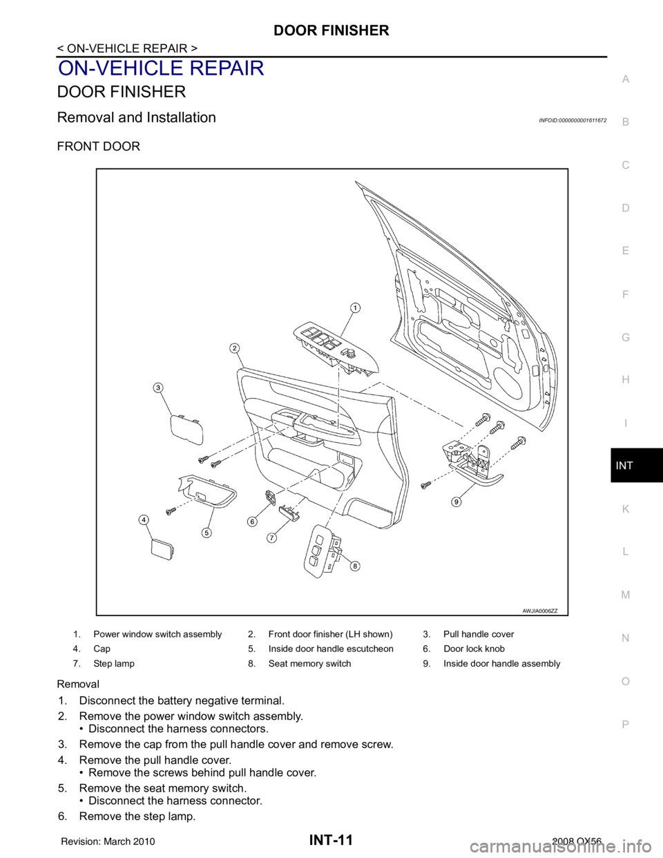
FRONT DOOR
Removal
1. Disconnect the battery negative terminal.
2. Remove the power window switch assembly. • Disconnect the harness connectors.
3. Remove the cap from the pull handle cover and remove screw.
4. Remove the pull handle cover. • Remove the screws behind pull handle cover.
5. Remove the seat memory switch. • Disconnect the harness connector.
6. Remove the step lamp.
1. Power window switch assembly 2. Front door finisher (LH shown) 3. Pull handle cover
4. Cap 5. Inside door handle escutcheon 6. Door lock knob
7. Step lamp 8. Seat memory switch 9. Inside door handle assembly
AWJIA0006ZZ
Revision: March 2010 2008 QX56
Page 2775 of 4083

PG-8
< BASIC INSPECTION >
INSPECTION AND ADJUSTMENT
INSPECTION AND ADJUSTMENT
ADDITIONAL SERVICE WHEN REMOVING BATTERY NEGATIVE TERMINAL
ADDITIONAL SERVICE WHEN REMOVING BATTERY NEGATIVE TERMINAL : Spe-
cial Repair Requirement
INFOID:0000000006095112
Required Procedure After Battery Disconnection
System ItemReference
Engine Control Idle Air Volume Learning Refer to EC-18
.
Brake Control Steering Angle Sensor Neutral Position Refer to BRC-8
.
Power Window Control Power Window System Initialization Refer to TSB.
Body, Lock & Security Automatic Back Door Initialization Refer to DLK-9
.
Roof Sunroof Memory Reset/Initialization Refer to RF-5
.
Seats Automatic Drive Positioner System Initialization Refer to Owner's Manual.
Audio-Visual System Audio (Radio Preset)
Refer to Owner's Manual.
Navigation System Refer to Owner's Manual.
Rear View Monitor Guiding Line Adjustment Refer to AV- 7
.
Revision: March 2010 2008 QX56
Page 2823 of 4083

PG-56
< COMPONENT DIAGNOSIS >
HARNESS
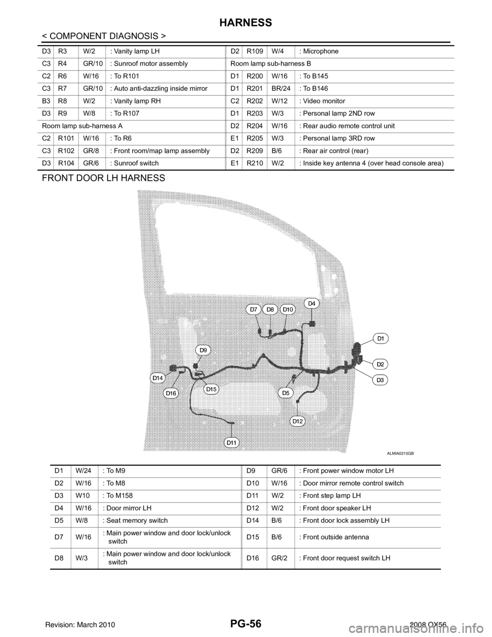
FRONT DOOR LH HARNESS
D3 R3 W/2 : Vanity lamp LHD2 R109 W/4 : Microphone
C3 R4 GR/10 : Sunroof motor assembly Room lamp sub-harness B
C2 R6 W/16 : To R101 D1 R200 W/16 : To B145
C3 R7 GR/10 : Auto anti-dazzling inside mirror D1 R201 BR/24 : To B146
B3 R8 W/2 : Vanity lamp RH C2 R202 W/12 : Video monitor
D3 R9 W/8 : To R107 D1 R203 W/3 : Personal lamp 2ND row
Room lamp sub-harness A D2 R204 W/16 : Rear audio remote control unit
C2 R101 W/16 : To R6 E1 R205 W/3 : Personal lamp 3RD row
C3 R102 GR/8 : Front room/map lamp assembly D2 R209 B/6 : Rear air control (rear)
D3 R104 GR/6 : Sunroof switch E1 R210 W/2 : Inside key antenna 4 (over head console area)
ALMIA0215GB
D1 W/24 : To M9 D9 GR/6 : Front power window motor LH
D2 W/16 : To M8 D10 W/16 : Door mirror remote control switch
D3 W10 : To M158 D11 W/2 : Front step lamp LH
D4 W/16 : Door mirror LH D12 W/2 : Front door speaker LH
D5 W/8 : Seat memory switch D14 B/6 : Front door lock assembly LH
D7 W/16 : Main power window and door lock/unlock
switch D15 B/6 : Front outside antenna
D8 W/3 : Main power window and door lock/unlock
switch
D16 GR/2 : Front door request switch LH
Revision: March 2010
2008 QX56