2008 INFINITI QX56 oil temperature
[x] Cancel search: oil temperaturePage 2616 of 4083
MA-18
< ON-VEHICLE MAINTENANCE >
ENGINE MAINTENANCE
2. Disconnect the harness connector, then remove the air cleaner case (upper).
3. Remove the air cleaner filter from the air cleaner case (lower).
4. Install the new air cleaner filter in the air cleaner case (lower).
5. Install the air cleaner case (upper) and connect the harness connector.
6. Install the air duct and resonator assembly.
Changing Engine OilINFOID:0000000001606175
WARNING:
• Be careful not to burn yourself, as the engine and engine oil are hot.
• Prolonged and repeated contact with used engine oil may cause skin cancer; try to avoid direct skin
contact with used oil. If skin contact is made, wash thoroughly with soap or hand cleaner as soon as
possible.
1. Warm up the engine, and check for any oil leaks.
2. Stop the engine and wait for at least 10 minutes.
3. Remove the oil drain plug and oil filler cap to drain the old oil.
4. Install a new washer on the oil drain plug, then install the oil drain plug in the oil pan.
CAUTION:
Clean the drain plug and install with a new washer.
5. Refill the engine with new specified engine oil.
CAUTION:
The refill capacity depends on th e oil temperature and drain time. Use the “Refill oil capacity” val-
ues as a reference and check the oil level using th e dipstick when filling the engine with oil.
6. Warm up the engine and check the area around the dr ain plug and oil filter for any oil leaks.
7. Stop the engine and wait for more than 10 minutes.
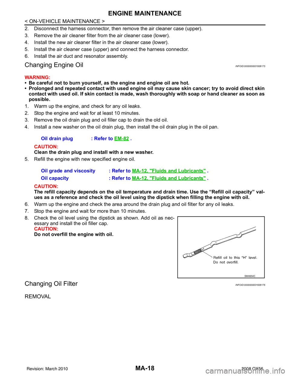
8. Check the oil level using the dipstick as shown. Add oil as nec- essary and install the oil filler cap.
CAUTION:
Do not overfill the engine with oil.
Changing Oil FilterINFOID:0000000001606176
REMOVAL
Oil drain plug : Refer to EM-82 .
Oil grade and viscosity : Refer to MA-12, "
Fluids and Lubricants" .
Oil capacity : Refer to MA-12, "
Fluids and Lubricants" .
SMA954C
Revision: March 2010 2008 QX56
Page 2629 of 4083
CHASSIS AND BODY MAINTENANCEMA-31
< ON-VEHICLE MAINTENANCE >
C
DE
F
G H
I
J
K L
M B
MA
N
O A
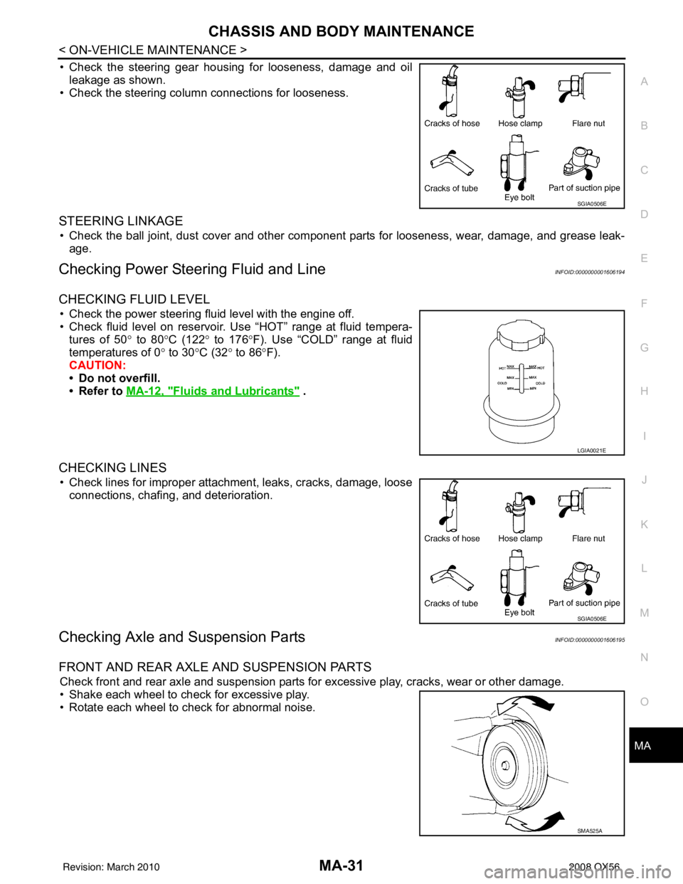
• Check the steering gear housing for looseness, damage and oil
leakage as shown.
• Check the steering column connections for looseness.
STEERING LINKAGE
• Check the ball joint, dust cover and other component parts for looseness, wear, damage, and grease leak-
age.
Checking Power Steering Fluid and LineINFOID:0000000001606194
CHECKING FLUID LEVEL
• Check the power steering fluid level with the engine off.
• Check fluid level on reservoir. Use “HOT” range at fluid tempera- tures of 50 ° to 80° C (122° to 176° F). Use “COLD” range at fluid
temperatures of 0 ° to 30° C (32° to 86° F).
CAUTION:
• Do not overfill.
• Refer to MA-12, "
Fluids and Lubricants" .
CHECKING LINES
• Check lines for improper attachment, leaks, cracks, damage, loose
connections, chafing, and deterioration.
Checking Axle and Suspension PartsINFOID:0000000001606195
FRONT AND REAR AXLE AND SUSPENSION PARTS
Check front and rear axle and suspension parts for excessive play, cracks, wear or other damage.
• Shake each wheel to check for excessive play.
• Rotate each wheel to check for abnormal noise.
SGIA0506E
LGIA0021E
SGIA0506E
SMA525A
Revision: March 2010 2008 QX56
Page 2646 of 4083

MWI
MWI-1
DRIVER INFORMATION & MULTIMEDIA
C
DE
F
G H
I
J
K L
M B
SECTION MWI
A
O P
CONTENTS
METER, WARNING LAMP & INDICATOR
BASIC INSPECTION ....... .............................4
DIAGNOSIS AND REPAIR WORKFLOW ..... .....4
Work Flow ........................................................... ......4
FUNCTION DIAGNOSIS ...............................5
METER SYSTEM ............................................ .....5
METER SYSTEM .........................................................5
METER SYSTEM : System Diagram ........................5
METER SYSTEM : System Description ....................5
METER SYSTEM : Arrangem ent of Combination
Meter ................................................................... ......
6
METER SYSTEM : Component Parts Location ........7
METER SYSTEM : Component Description ....... ......7
SPEEDOMETER ..........................................................8
SPEEDOMETER : System Diagram ................... ......8
SPEEDOMETER : System Description .....................8
SPEEDOMETER : Component Parts Location .........9
SPEEDOMETER : Component Description ........ ......9
TACHOMETER ...................................................... ......9
TACHOMETER : System Diagram ...........................9
TACHOMETER : System De scription .....................10
TACHOMETER : Component Parts Location ..... ....10
TACHOMETER : Component Description ..............10
ENGINE COOLANT TEMPERATURE GAUGE .... ....10
ENGINE COOLANT TEMPERATURE GAUGE :
System Diagram ......................................................
11
ENGINE COOLANT TEMPERATURE GAUGE :
System Description .................................................
11
ENGINE COOLANT TEMPERATURE GAUGE :
Component Parts Location ......................................
11
ENGINE COOLANT TEMPERATURE GAUGE :
Component Description ...........................................
12
FUEL GAUGE ........................................................ ....12
FUEL GAUGE : System Diagram ...........................12
FUEL GAUGE : System Description .......................12
FUEL GAUGE : Component Parts Location ...........12
FUEL GAUGE : Component Description ............. ....13
ENGINE OIL PRESSURE GAUGE ............................13
ENGINE OIL PRESSURE GAUGE : System Dia-
gram .................................................................... ....
13
ENGINE OIL PRESSURE GAUGE : System De-
scription ...................................................................
13
ENGINE OIL PRESSURE GAUGE : Component
Parts Location ..........................................................
14
ENGINE OIL PRESSURE GAUGE : Component
Description ...............................................................
14
VOLTAGE GAUGE ................................................ ....14
VOLTAGE GAUGE : System Diagram ....................15
VOLTAGE GAUGE : System Description ................15
VOLTAGE GAUGE : Component Parts Location ....15
VOLTAGE GAUGE : Component Description .........16
ODO/TRIP METER ................................................. ....16
ODO/TRIP METER : System Diagram ....................16
ODO/TRIP METER : System Description ................16
ODO/TRIP METER : Component Parts Location ....16
ODO/TRIP METER : Component Description .........17
SHIFT POSITION INDICATOR .............................. ....17
SHIFT POSITION INDICATOR : System Diagram ....17
SHIFT POSITION INDICATOR : System Descrip-
tion ...........................................................................
17
SHIFT POSITION INDICATOR : Component
Parts Location ..........................................................
18
SHIFT POSITION INDICATOR : Component De-
scription ............................................................... ....
18
WARNING LAMPS/INDICATOR LAMPS .............. ....18
WARNING LAMPS/INDICATOR LAMPS : System
Diagram ............................................................... ....
18
WARNING LAMPS/INDICATOR LAMPS : System
Description ........................................................... ....
19
WARNING LAMPS/INDICATOR LAMPS : Com-
ponent Parts Location ..............................................
19
WARNING LAMPS/INDICATOR LAMPS : Com-
ponent Description ...................................................
19
Revision: March 2010 2008 QX56
Page 2650 of 4083
MWI
METER SYSTEMMWI-5
< FUNCTION DIAGNOSIS >
C
DE
F
G H
I
J
K L
M B A
O P
FUNCTION DIAGNOSIS
METER SYSTEM
METER SYSTEM
METER SYSTEM : System DiagramINFOID:0000000001691233
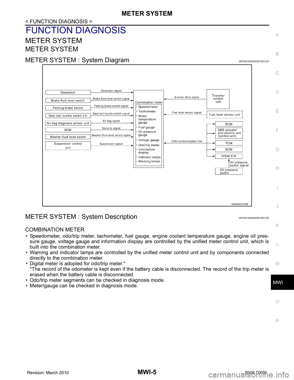
METER SYSTEM : System DescriptionINFOID:0000000001691234
COMBINATION METER
• Speedometer, odo/trip meter, tachometer, fuel gauge, engine coolant temperature gauge, engine oil pres-
sure gauge, voltage gauge and information display are controlled by the unified meter control unit, which is
built into the combination meter.
• Warning and indicator lamps are controlled by the unified meter control unit and by components connected directly to the combination meter.
• Digital meter is adopted for odo/trip meter.* *The record of the odometer is kept even if the battery cable is disconnected. The record of the trip meter is
erased when the battery cable is disconnected.
• Odo/trip meter segments can be checked in diagnosis mode.
• Meter/gauge can be checked in diagnosis mode.
AWNIA0274GB
Revision: March 2010 2008 QX56
Page 2652 of 4083
MWI
METER SYSTEMMWI-7
< FUNCTION DIAGNOSIS >
C
DE
F
G H
I
J
K L
M B A
O P
METER SYSTEM : Com ponent Parts LocationINFOID:0000000001691236
METER SYSTEM : Component DescriptionINFOID:0000000001691237
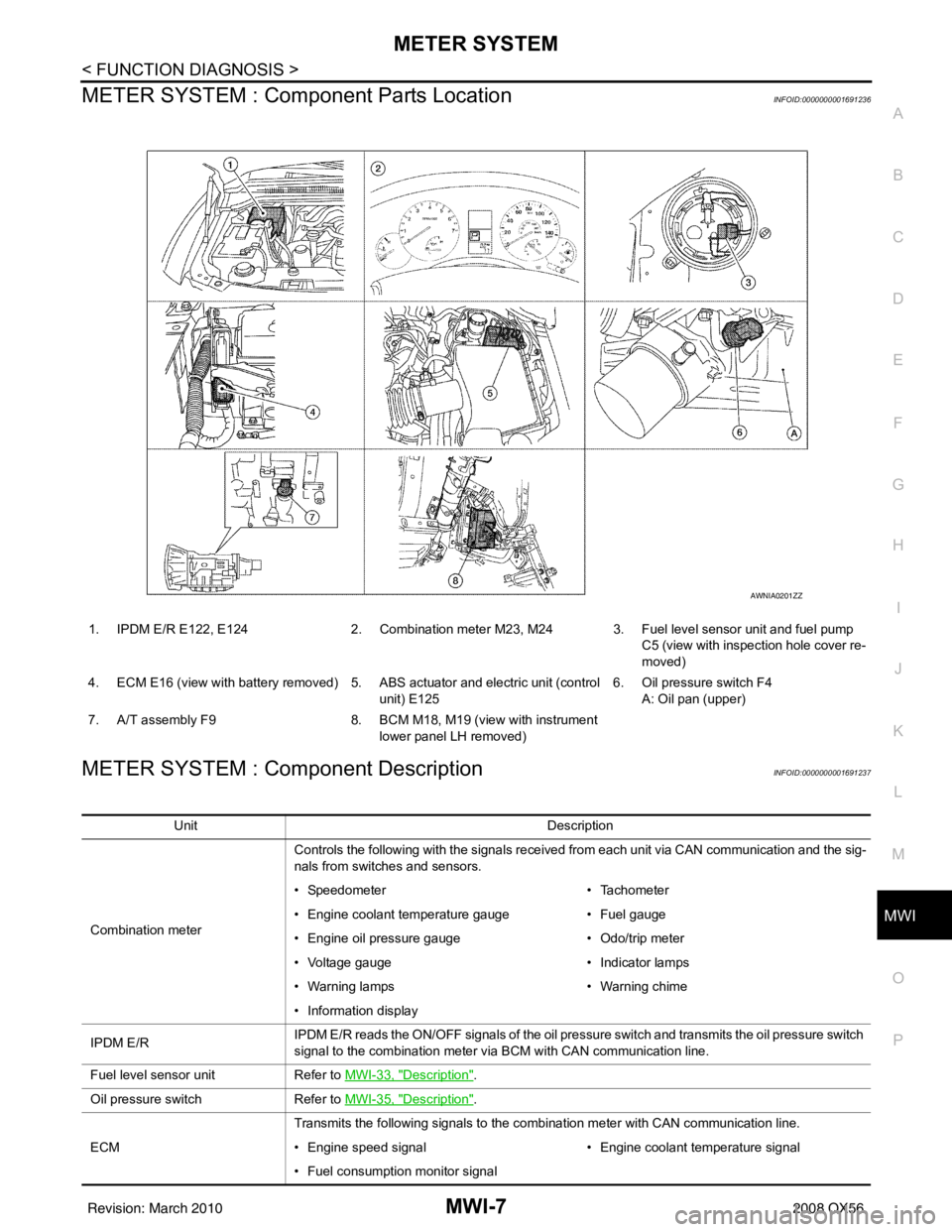
1. IPDM E/R E122, E124 2. Combination meter M23, M24 3. Fuel level sensor unit and fuel pump
C5 (view with inspection hole cover re-
moved)
4. ECM E16 (view with battery removed) 5. ABS actuator and electric unit (control unit) E1256. Oil pressure switch F4
A: Oil pan (upper)
7. A/T assembly F9 8. BCM M18, M19 (view with instrument
lower panel LH removed)
AWNIA0201ZZ
Unit Description
Combination meter Controls the following with the signals received from each unit via CAN communication and the sig-
nals from switches and sensors.
• Speedometer
• Tachometer
• Engine coolant temperature gauge • Fuel gauge
• Engine oil pressure gauge • Odo/trip meter
• Voltage gauge • Indicator lamps
• Warning lamps • Warning chime
• Information display
IPDM E/R IPDM E/R reads the ON/OFF signals of the oil pressure switch and transmits the oil pressure switch
signal to the combination meter via BCM with CAN communication line.
Fuel level sensor unit Refer to MWI-33, "
Description".
Oil pressure switch Refer to MWI-35, "
Description".
ECM Transmits the following signals to the combination meter with CAN communication line.
• Engine speed signal
• Engine coolant temperature signal
• Fuel consumption monitor signal
Revision: March 2010 2008 QX56
Page 2653 of 4083
MWI-8
< FUNCTION DIAGNOSIS >
METER SYSTEM
SPEEDOMETER
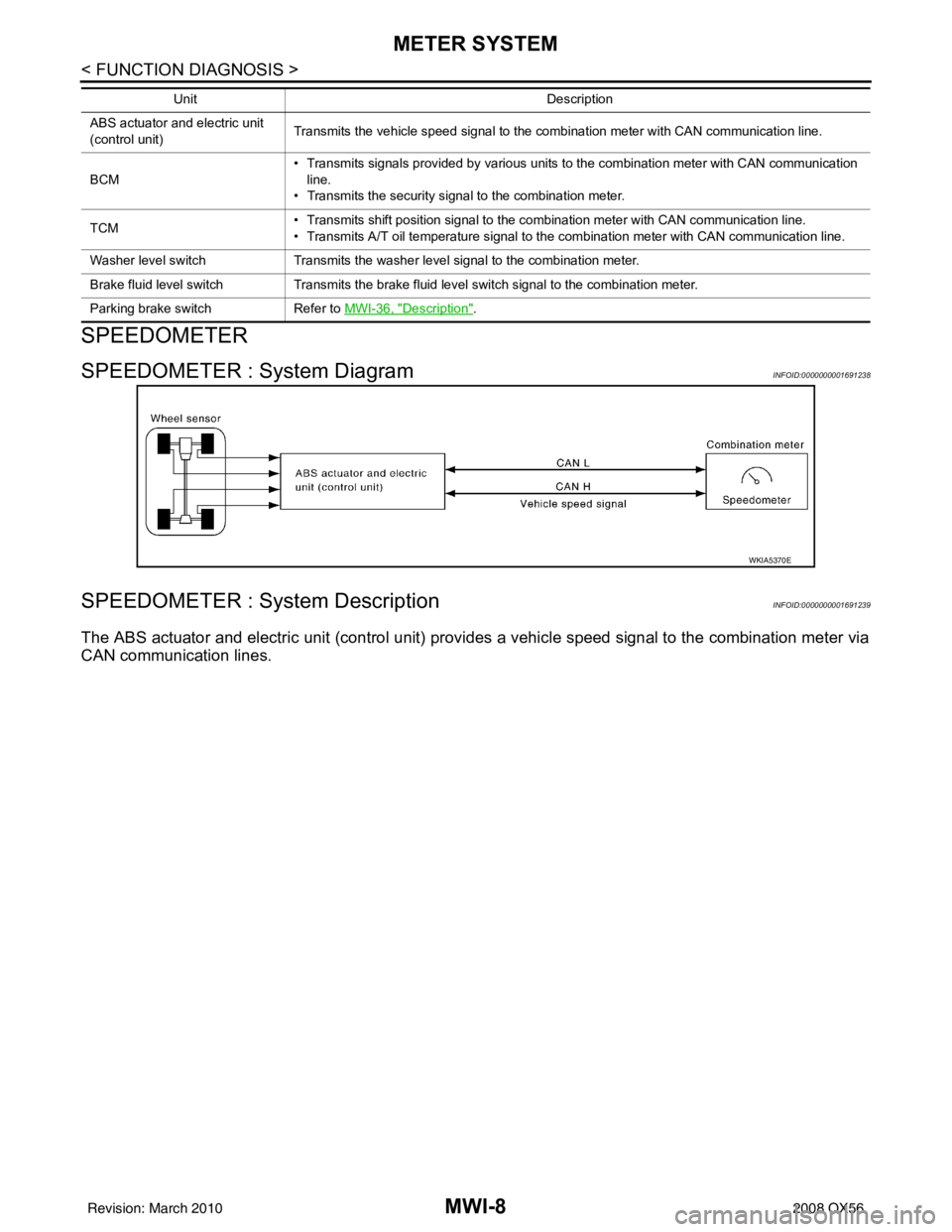
SPEEDOMETER : System DiagramINFOID:0000000001691238
SPEEDOMETER : System DescriptionINFOID:0000000001691239
The ABS actuator and electric unit (control unit) provides a vehicle speed signal to the combination meter via
CAN communication lines.
ABS actuator and electric unit
(control unit) Transmits the vehicle speed signal to the combination meter with CAN communication line.
BCM • Transmits signals provided by various units to the combination meter with CAN communication
line.
• Transmits the security signal to the combination meter.
TCM • Transmits shift position signal to the combination meter with CAN communication line.
• Transmits A/T oil temperature signal to the combination meter with CAN communication line.
Washer level switch Transmits the washer level signal to the combination meter.
Brake fluid level switch Transmits the brake fluid level switch signal to the combination meter.
Parking brake switch Refer to MWI-36, "
Description".
Unit
Description
WKIA5370E
Revision: March 2010 2008 QX56
Page 2655 of 4083
MWI-10
< FUNCTION DIAGNOSIS >
METER SYSTEM
TACHOMETER : System Description
INFOID:0000000001691243
The tachometer indicates engine speed in revolutions per minute (rpm).
The ECM provides an engine speed signal to the co mbination meter via CAN communication lines.
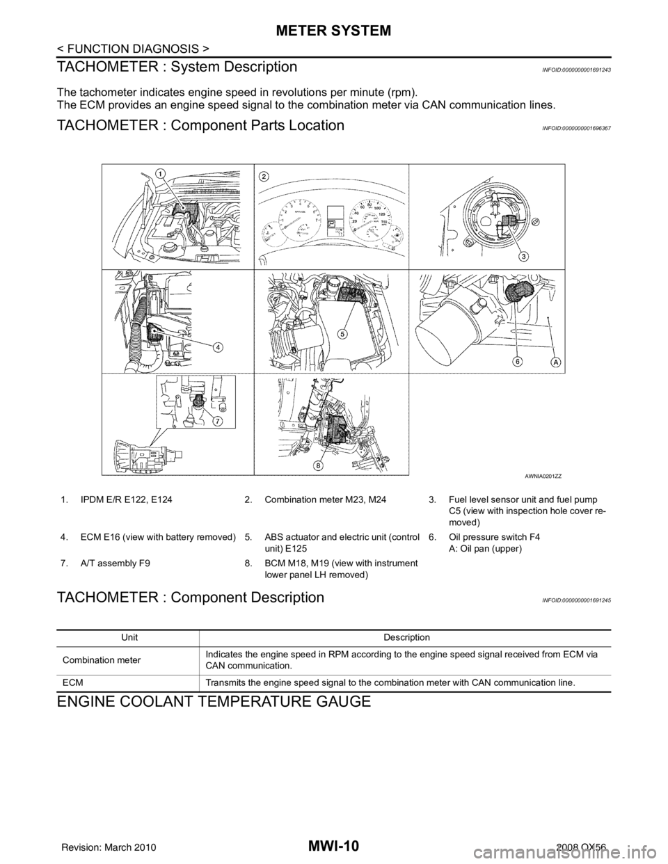
TACHOMETER : Component Parts LocationINFOID:0000000001696367
TACHOMETER : Component DescriptionINFOID:0000000001691245
ENGINE COOLANT TEMPERATURE GAUGE
1. IPDM E/R E122, E1242. Combination meter M23, M24 3. Fuel level sensor unit and fuel pump
C5 (view with inspection hole cover re-
moved)
4. ECM E16 (view with battery removed) 5. ABS actuator and electric unit (control
unit) E125 6. Oil pressure switch F4
A: Oil pan (upper)
7. A/T assembly F9 8. BCM M18, M19 (view with instrument
lower panel LH removed)
AWNIA0201ZZ
Unit Description
Combination meter Indicates the engine speed in RPM according to the engine speed signal received from ECM via
CAN communication.
ECM Transmits the engine speed signal to the combination meter with CAN communication line.
Revision: March 2010 2008 QX56
Page 2656 of 4083
MWI
METER SYSTEMMWI-11
< FUNCTION DIAGNOSIS >
C
DE
F
G H
I
J
K L
M B A
O P
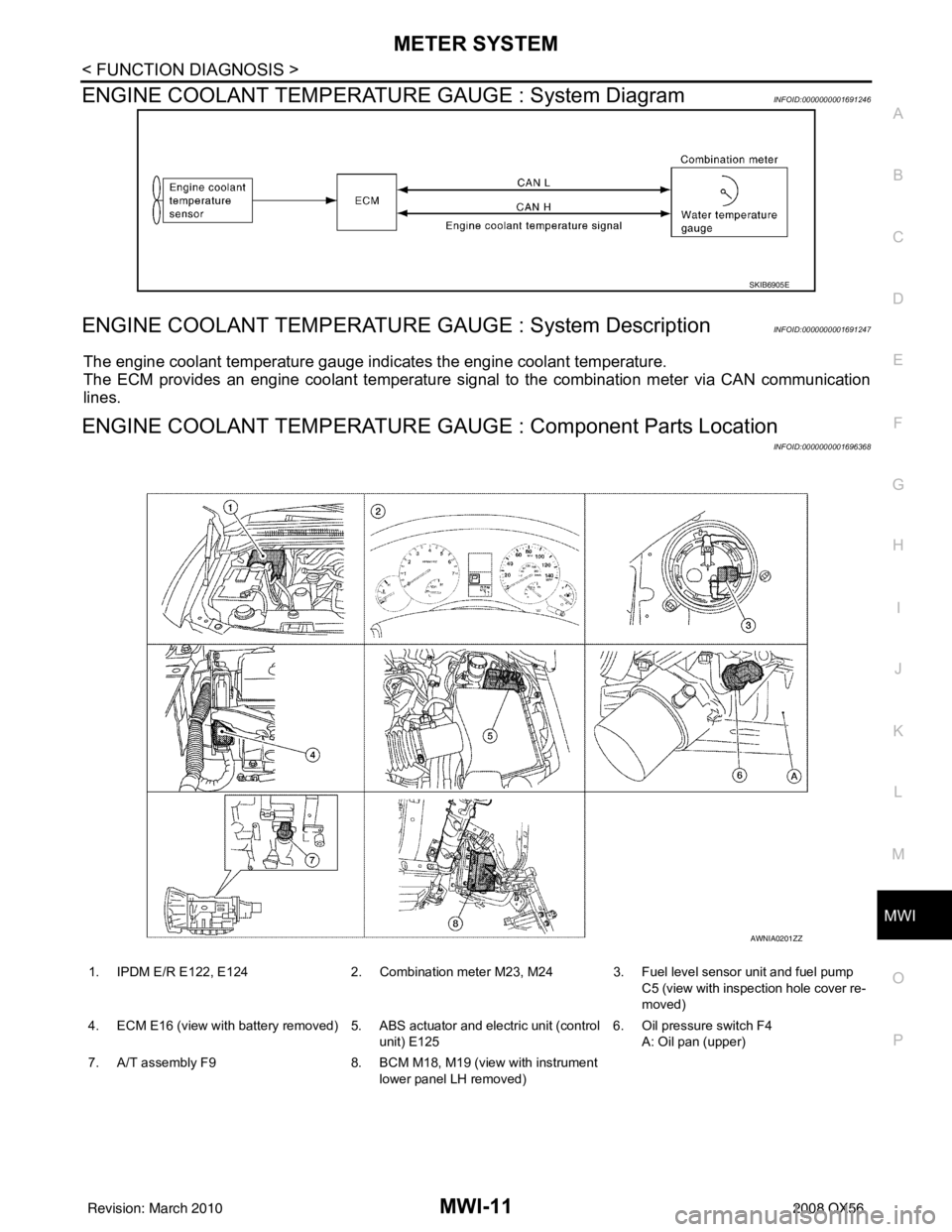
ENGINE COOLANT TEMPERATURE GAUGE : System DiagramINFOID:0000000001691246
ENGINE COOLANT TEMPERATURE GAUGE : System DescriptionINFOID:0000000001691247
The engine coolant temperature gauge indicates the engine coolant temperature.
The ECM provides an engine coolant temperature signal to the combination meter via CAN communication
lines.
ENGINE COOLANT TEMPERATURE GA UGE : Component Parts Location
INFOID:0000000001696368
SKIB6905E
1. IPDM E/R E122, E124 2. Combination meter M23, M24 3. Fuel level sensor unit and fuel pump
C5 (view with inspection hole cover re-
moved)
4. ECM E16 (view with battery removed) 5. ABS actuator and electric unit (control unit) E1256. Oil pressure switch F4
A: Oil pan (upper)
7. A/T assembly F9 8. BCM M18, M19 (view with instrument
lower panel LH removed)
AWNIA0201ZZ
Revision: March 2010 2008 QX56