2008 INFINITI QX56 oil temperature
[x] Cancel search: oil temperaturePage 3722 of 4083
PRECAUTIONSTM-175
< PRECAUTION >
CEF
G H
I
J
K L
M A
B
TM
N
O P
• All parts should be carefully cleaned with a general purpose, non-flammable solvent before inspection or reassembly.
• Gaskets, seals and O-rings should be replaced any time the transmission is disassembled.
• It is very important to perform func tional tests whenever they are indicated.
• The valve body contains precision parts and requires extreme care when parts are removed and serviced. Place disassembled valve body parts in order for easier and proper assembly. Care will also prevent springs
and small parts from becoming scattered or lost.
• Properly installed valves, sleeves, plugs, etc. will slide along bores in valve body under their own weight.
• Before assembly, apply a coat of recommended ATF to all parts. Apply petroleum jelly to protect O-rings and
seals, or hold bearings and washers in pl ace during assembly. Do not use grease.
• Extreme care should be taken to avoid damage to O-rings, seals and gaskets when assembling.
• Clean or replace ATF cooler if excessive foreign material is found in oil pan or clogging strainer. Refer to TM-
182, "A/T Fluid Cooler Cleaning".
• After overhaul, refill the transmission with new ATF.
• When the A/T drain plug is removed, only some of the fluid is drained. Old A/T fluid will remain in torque con- verter and ATF cooling system.
Always follow the procedures under “Changing A/T Fluid” in the AT section when changing A/T fluid. Refer to
TM-180, "
Changing the A/T Fluid (ATF)".
Service Notice or PrecautionINFOID:0000000001531487
ATF COOLER SERVICE
• If A/T fluid contains fictional material (clutches, bands, etc.), or if an A/T is repaired, overhauled, or replaced,
inspect and clean the A/T fluid cooler mounted in the radiat or or replace the radiator. Flush cooler lines with
cleaning solvent and compressed air after repair. For A/T fluid cooler cleaning procedure, refer to TM-182,
"A/T Fluid Cooler Cleaning". For radiator replacement, refer to CO-15, "Removal and Installation".
CHECKING AND CHANGING A/T FLUID
• Increase ATF oil temperature to 80 °C (176° F) first, then check and adjust oil level at 65 °C (149° F).
NOTE:
The A/T has both water cooling and air cooling systems. The air cooling system has a bypass valve. When
ATF oil temperature is at or below 50 °C (122° F), it does not flow through the air cooled system. If A/T oil
level is adjusted without flow throughout the entir e system, the level will be 10mm lower than required.
Therefore, all piping should be filled with oil when adjusting level.
OBD-II SELF-DIAGNOSIS
• A/T self-diagnosis is performed by the TCM in combination with the ECM. Refer to the table on TM-32,
"CONSULT-III Function (TRANSMISSION)" for the indicator used to display each self-diagnostic result.
• The self-diagnostic results indicated by the MIL are automatically stored in both the ECM and TCM memo- ries.
Always perform the procedure on TM-30, "
OBD-II Diagnostic Trouble Code (DTC)" to complete the
repair and avoid unnecessary blinking of the MIL.
For details of OBD-II, refer to TM-30
.
• Certain systems and components, especially those related to OBD, may use the new style slide-
locking type harness connector. For descrip tion and how to disconnect, refer to PG-65
.
Revision: March 2010 2008 QX56
Page 3732 of 4083
STALL TESTTM-185
< ON-VEHICLE MAINTENANCE >
CEF
G H
I
J
K L
M A
B
TM
N
O P
STALL TEST
Inspection and JudgmentINFOID:0000000001696156
A/T FLUID CHECK
Fluid Leakage and Fluid Level Check
• Inspect for fluid leakage and check the fluid level. Refer to TM-178, "Checking the A/T Fluid (ATF)".
Fluid Condition Check
Inspect the fluid condition.
STALL TEST
Stall Test Procedure
1. Inspect the amount of engine oil. Replenish the engine oil if necessary.
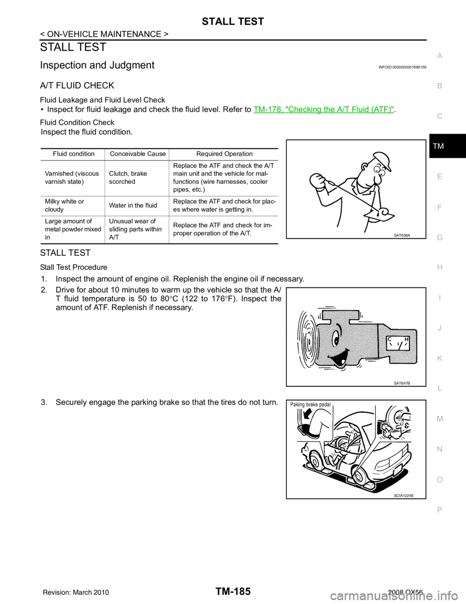
2. Drive for about 10 minutes to warm up the vehicle so that the A/
T fluid temperature is 50 to 80 °C (122 to 176 °F). Inspect the
amount of ATF. Replenish if necessary.
3. Securely engage the parking brake so that the tires do not turn.
Fluid condition Conceivable Cause Required Operation
Varnished (viscous
varnish state) Clutch, brake
scorchedReplace the ATF and check the A/T
main unit and the vehicle for mal-
functions (wire harnesses, cooler
pipes, etc.)
Milky white or
cloudy Water in the fluidReplace the ATF and check for plac-
es where water is getting in.
Large amount of
metal powder mixed
in Unusual wear of
sliding parts within
A/T
Replace the ATF and check for im-
proper operation of the A/T.
SAT638A
SAT647B
SCIA1224E
Revision: March 2010
2008 QX56
Page 3734 of 4083
LINE PRESSURE TESTTM-187
< ON-VEHICLE MAINTENANCE >
CEF
G H
I
J
K L
M A
B
TM
N
O P
LINE PRESSURE TEST
Inspection and JudgmentINFOID:0000000001696157
LINE PRESSURE TEST
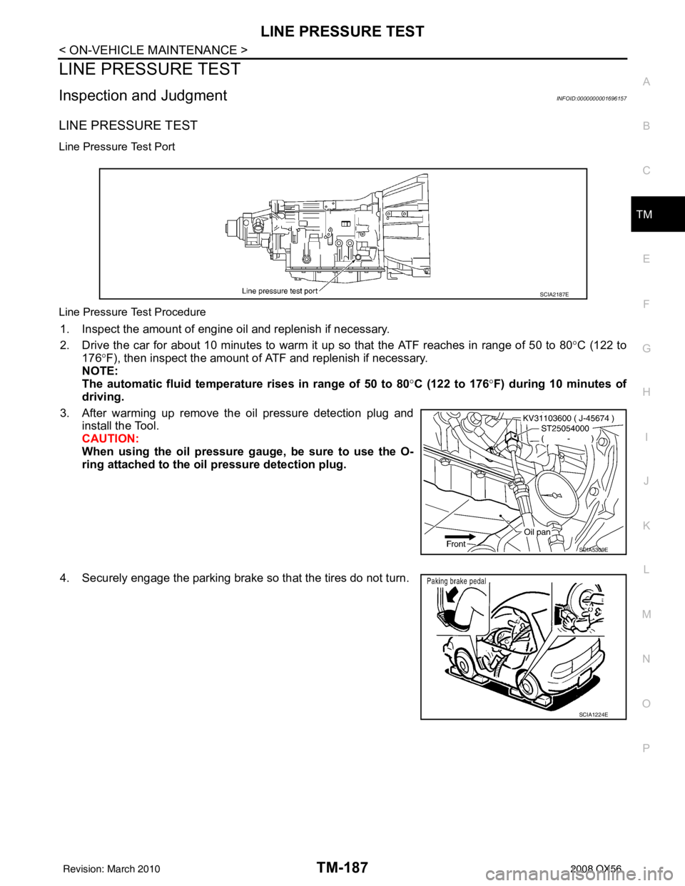
Line Pressure Test Port
Line Pressure Test Procedure
1. Inspect the amount of engine oil and replenish if necessary.
2. Drive the car for about 10 minutes to warm it up so that the ATF reaches in range of 50 to 80 °C (122 to
176° F), then inspect the amount of ATF and replenish if necessary.
NOTE:
The automatic fluid temperature rises in range of 50 to 80 °C (122 to 176° F) during 10 minutes of
driving.
3. After warming up remove the oil pressure detection plug and install the Tool.
CAUTION:
When using the oil pressure ga uge, be sure to use the O-
ring attached to the oil pressure detection plug.
4. Securely engage the parking brake so that the tires do not turn.
SCIA2187E
SCIA5309E
SCIA1224E
Revision: March 2010 2008 QX56
Page 3735 of 4083
TM-188
< ON-VEHICLE MAINTENANCE >
LINE PRESSURE TEST
5. Start the engine, then measure the line pressure at both idle andthe stall speed.
CAUTION:
• Keep the brake pedal pressed all the way down duringmeasurement.
• When measuring the line pressure at the stall speed, refer
to TM-185, "
Inspection and Judgment".
6. After the measurements are complete, install the oil pressure detection plug and tighten to the regulation torque below.
CAUTION:
Do not reuse the O-ring.
Line Pressure
Judgement of Line Pressure Test
Oil pressure detection
plug :7.3 N·m (0.74 kg-m, 65 in-lb)SAT493G
Engine speed
Line pressure [kPa (kg/cm
2, psi)]
R position D position
At idle speed 425 - 465 (4.3 - 4.7, 62 - 67) 379 - 428 (3.9 - 4.4, 55 - 62)
At stall speed 1,605 - 1,950 (16.4 - 19.9, 233 - 283) 1,310 - 1,500 (13.4 - 15.3, 190 - 218)
Judgement Possible cause
Idle speed Low for all positions
(P, R, N, D)
Possible causes include malfunctions in the pressure supply system and low oil pump output.
For example
•Oil pump wear
• Pressure regulator valve or plug sticking or spring fatigue
• Oil strainer ⇒ oil pump
⇒ pressure regulator valve passage oil leak
• Engine idle speed too low
Only low for a spe-
cific position Possible causes include an oil pressure leak in a passage or device related to the position after
the pressure is distributed by the manual valve.
High Possible causes include a sensor malfunction or malfunction in the line pressure adjustment func-
tion.
For example
• Accelerator pedal position signal malfunction
• ATF temperature sensor malfunction
• Line pressure solenoid malfunction (sticking in “OFF” state, filter clog, cut line)
• Pressure regulator valve or plug sticking
Sta ll sp ee d Oil pressure does
not rise higher than
the oil pressure for
idle.
Possible causes include a sensor malfunction or malfunction in the pressure adjustment function.
For example
• Accelerator pedal position signal malfunction
• TCM breakdown
• Line pressure solenoid malfunction (shorting, sticking in“ ON” state)
• Pressure regulator valve or plug sticking
• Pilot valve sticking or pilot filter clogged
The pressure rises,
but does not enter
the standard posi-
tion. Possible causes include malfunctions in the pressure supply system and malfunction in the pres-
sure adjustment function.
For example
• Accelerator pedal position signal malfunction
• Line pressure solenoid malfunction (sticking, filter clog)
• Pressure regulator valve or plug sticking
• Pilot valve sticking or pilot filter clogged
Only low for a spe-
cific position Possible causes include an oil pressure leak in a passage or device related to the position after
the pressure is distributed by the manual valve.
Revision: March 2010
2008 QX56
Page 3737 of 4083
TM-190
< ON-VEHICLE MAINTENANCE >
ROAD TEST
YES >> Enter a check mark at “In “P” Position Vehicle Moves When Pushed” on the diagnostics work-sheet, then continue the road test.
NO >> GO TO 4.
4.CHECK “N” POSITION FUNCTIONS
1. Start the engine.
2. Move selector lever to “N” position.
3. Release the parking brake.
Does vehicle move forward or backward?
YES >> Enter a check mark at “In “N” Position Vehicle Moves” on the diagnostics worksheet, then con- tinue the road test.
NO >> GO TO 5.
5.CHECK SHIFT SHOCK
1. Engage the brake.
2. Move selector lever to “D” position.
When the transmission is shifted from
“N” to “D”, is there an excessive shock?
YES >> Enter a check mark at “Large Shock ("N" to "D" Position) on the diagnostics worksheet, then con-
tinue the road test.
NO >> GO TO 6.
6.CHECK “R” POSITION FUNCTIONS
1. Engage the brake.
2. Move selector lever to “R” position.
3. Release the brake for 4 to 5 seconds.
Does the vehicle creep backward?
YES >> GO TO 7.
NO >> Enter a check mark at “Vehicle Does Not Creep Backward In "R" Position” on the diagnostics
worksheet, then continue the road test.
7.CHECK “D” POSITION FUNCTIONS
Inspect whether the vehicle creeps forward when the transmission is put into the “D” position.
Does the vehicle creep forward in the
“D” positions?
YES >> Go to TM-190, "Cruise Test - Part 1", TM-192, "Cruise Test - Part 2", and TM-193, "Cruise Test -
Part 3".
NO >> Enter a check mark at “Vehicle Does Not Cr eep Forward in "D" Position” on the diagnostics work-
sheet, then continue the road test.
Cruise Test - Part 1INFOID:0000000001696161
1.CHECK STARTING OUT FROM D1
1. Drive the vehicle for about 10 minutes to warm up the engine oil and ATF. Appropriate temperature for the ATF: 50 - 80° C (122 - 176°F)
2. Park the vehicle on a level surface.
3. Move selector lever to “P” position.
4. Start the engine.
5. Move selector lever to “D” position.
6. Press the accelerator pedal about half way down to accelerate the vehicle.
With CONSULT-III
Read off the gear positions.
Starts from D1?
YES >> GO TO 2.
NO >> Enter a check mark at “Vehicle Cannot be St arted From D1” on the diagnostics worksheet, then
continue the road test.
2.CHECK SHIFT-UP D1 → D2
Press down the accelerator pedal about half way and inspect if the vehicle shifts up (D1 → D2) at the appropri-
ate speed.
Revision: March 2010 2008 QX56
Page 3748 of 4083
CONTROL VALVE WITH TCMTM-201
< ON-VEHICLE REPAIR >
CEF
G H
I
J
K L
M A
B
TM
N
O P
CONTROL VALVE WITH TCM
Control Valve with TCM and A/T Fluid Temperature Sensor 2INFOID:0000000006211127
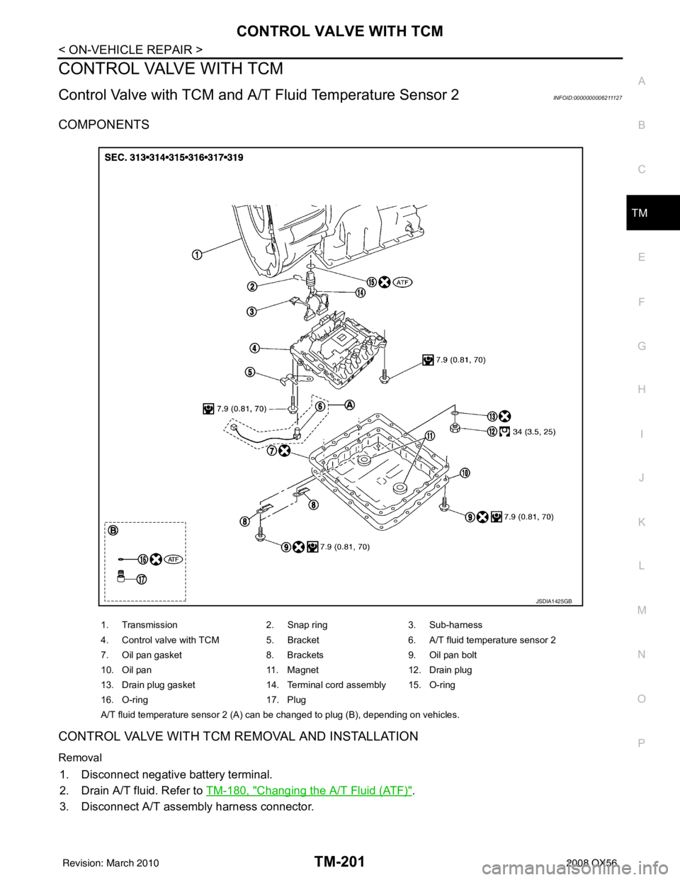
COMPONENTS
CONTROL VALVE WITH TCM REMOVAL AND INSTALLATION
Removal
1. Disconnect negative battery terminal.
2. Drain A/T fluid. Refer to TM-180, "
Changing the A/T Fluid (ATF)".
3. Disconnect A/T assembly harness connector.
1. Transmission 2. Snap ring3. Sub-harness
4. Control valve with TCM 5. Bracket6. A/T fluid temperature sensor 2
7. Oil pan gasket 8. Brackets9. Oil pan bolt
10. Oil pan 11. Magnet12. Drain plug
13. Drain plug gasket 14. Terminal cord assembly 15. O-ring
16. O-ring 17. Plug
A/T fluid temperature sensor 2 (A) can be changed to plug (B), depending on vehicles.
JSDIA1425GB
Revision: March 2010 2008 QX56
Page 3749 of 4083
TM-202
< ON-VEHICLE REPAIR >
CONTROL VALVE WITH TCM
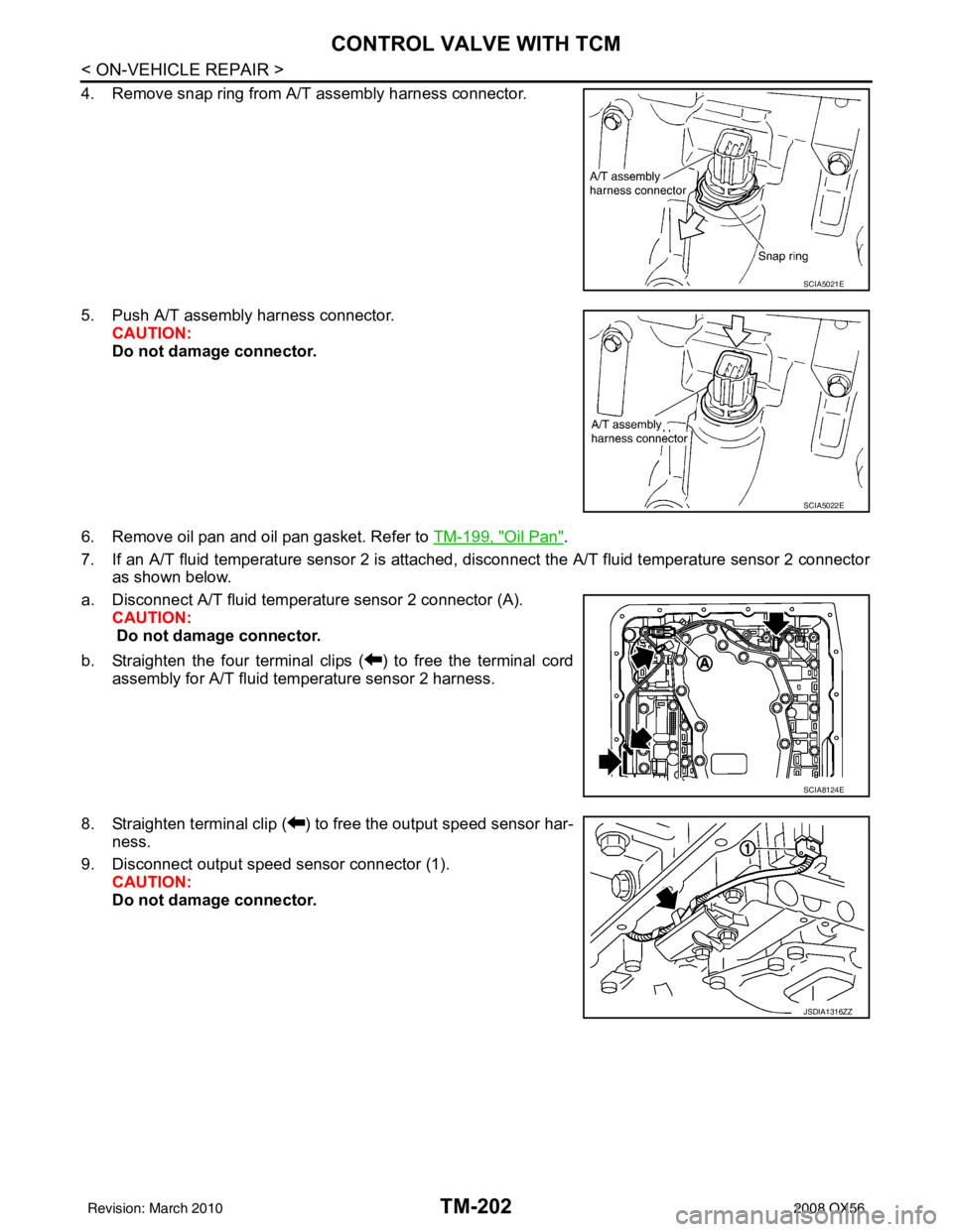
4. Remove snap ring from A/T assembly harness connector.
5. Push A/T assembly harness connector.CAUTION:
Do not damage connector.
6. Remove oil pan and oil pan gasket. Refer to TM-199, "
Oil Pan".
7. If an A/T fluid temperature sensor 2 is attached, disconnect the A/T fluid temperature sensor 2 connector
as shown below.
a. Disconnect A/T fluid temperat ure sensor 2 connector (A).
CAUTION:
Do not damage connector.
b. Straighten the four terminal clips ( ) to free the terminal cord assembly for A/T fluid temperature sensor 2 harness.
8. Straighten terminal clip ( ) to free the output speed sensor har- ness.
9. Disconnect output speed sensor connector (1). CAUTION:
Do not damage connector.
SCIA5021E
SCIA5022E
SCIA8124E
JSDIA1316ZZ
Revision: March 2010 2008 QX56
Page 3756 of 4083
CONTROL VALVE WITH TCMTM-209
< ON-VEHICLE REPAIR >
CEF
G H
I
J
K L
M A
B
TM
N
O P
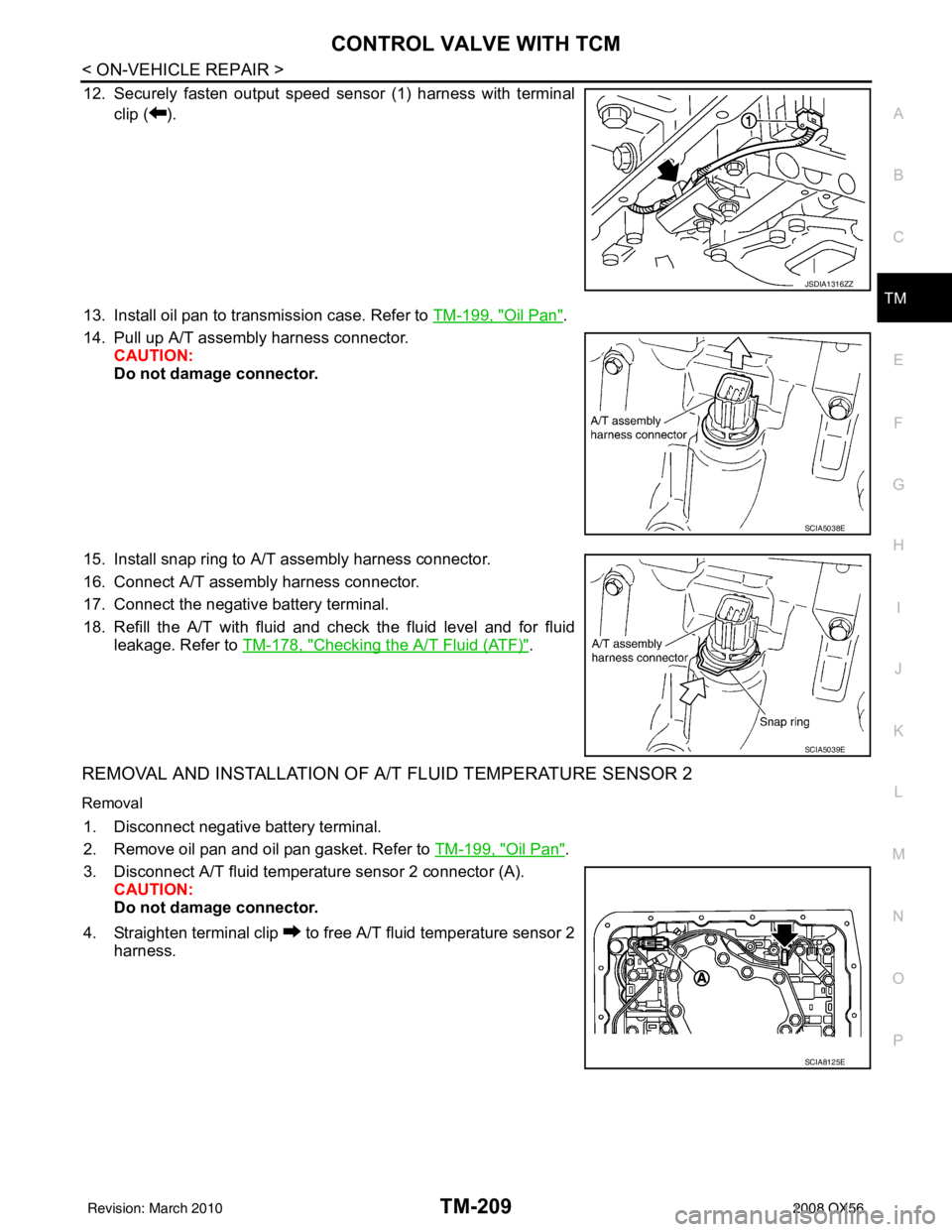
12. Securely fasten output speed sensor (1) harness with terminal clip ( ).
13. Install oil pan to transmission case. Refer to TM-199, "
Oil Pan".
14. Pull up A/T assembly harness connector. CAUTION:
Do not damage connector.
15. Install snap ring to A/T assembly harness connector.
16. Connect A/T assembly harness connector.
17. Connect the negative battery terminal.
18. Refill the A/T with fluid and check the fluid level and for fluid leakage. Refer to TM-178, "
Checking the A/T Fluid (ATF)".
REMOVAL AND INSTALLATION OF A/T FLUID TEMPERATURE SENSOR 2
Removal
1. Disconnect negative battery terminal.
2. Remove oil pan and oil pan gasket. Refer to TM-199, "
Oil Pan".
3. Disconnect A/T fluid temperat ure sensor 2 connector (A).
CAUTION:
Do not damage connector.
4. Straighten terminal clip to free A/T fluid temperature sensor 2 harness.
JSDIA1316ZZ
SCIA5038E
SCIA5039E
SCIA8125E
Revision: March 2010 2008 QX56