2008 INFINITI QX56 Stop
[x] Cancel search: StopPage 3504 of 4083
POWER STEERING FLUIDST-13
< ON-VEHICLE MAINTENANCE >
C
DE
F
H I
J
K L
M A
B
ST
N
O P
ON-VEHICLE MAINTENANCE
POWER STEERING FLUID
Checking Fluid LevelINFOID:0000000001534691
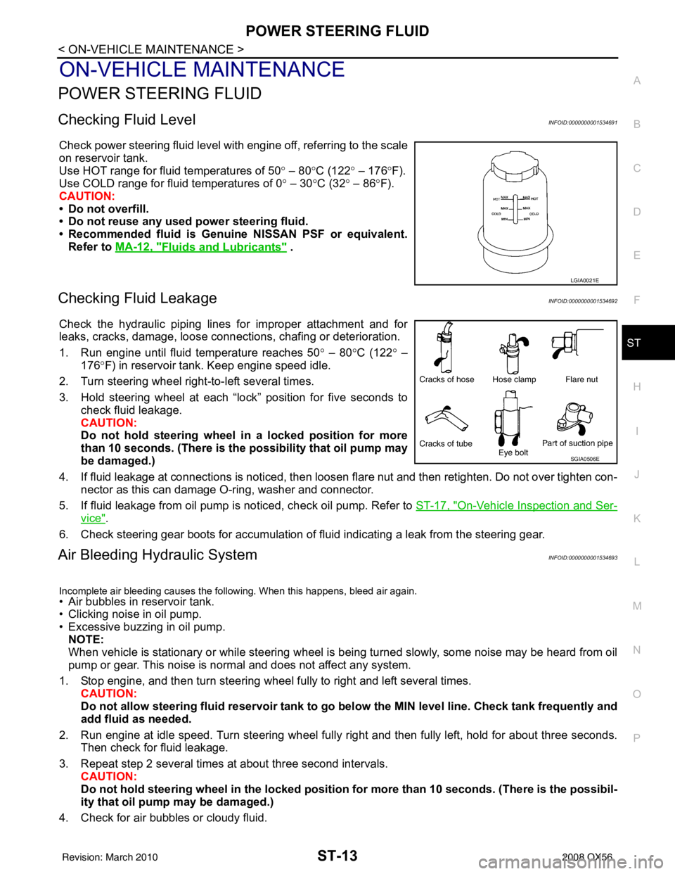
Check power steering fluid level with engine off, referring to the scale
on reservoir tank.
Use HOT range for fluid temperatures of 50 ° – 80 °C (122 ° – 176 °F).
Use COLD range for fluid temperatures of 0 ° – 30 °C (32° – 86°F).
CAUTION:
• Do not overfill.
• Do not reuse any used power steering fluid.
• Recommended fluid is Genuine NISSAN PSF or equivalent. Refer to MA-12, "
Fluids and Lubricants" .
Checking Fluid LeakageINFOID:0000000001534692
Check the hydraulic piping lines for improper attachment and for
leaks, cracks, damage, loose connec tions, chafing or deterioration.
1. Run engine until fluid temperature reaches 50 ° – 80° C (122° –
176° F) in reservoir tank. Keep engine speed idle.
2. Turn steering wheel right-to-left several times.
3. Hold steering wheel at each “lock” position for five seconds to check fluid leakage.
CAUTION:
Do not hold steering wheel in a locked position for more
than 10 seconds. (There is the possibility that oil pump may
be damaged.)
4. If fluid leakage at connections is noticed, then loosen flare nut and then retighten. Do not over tighten con- nector as this can damage O-ring, washer and connector.
5. If fluid leakage from oil pump is noticed, check oil pump. Refer to ST-17, "
On-Vehicle Inspection and Ser-
vice".
6. Check steering gear boots for accumulation of fluid indicating a leak from the steering gear.
Air Bleeding Hydraulic SystemINFOID:0000000001534693
Incomplete air bleeding causes the following. When this happens, bleed air again.
• Air bubbles in reservoir tank.
• Clicking noise in oil pump.
• Excessive buzzing in oil pump. NOTE:
When vehicle is stationary or while steering wheel is being turned slowly, some noise may be heard from oil
pump or gear. This noise is normal and does not affect any system.
1. Stop engine, and then turn steering wheel fully to right and left several times. CAUTION:
Do not allow steering fluid reservoir tank to go below the MIN level line. Check tank frequently and
add fluid as needed.
2. Run engine at idle speed. Turn steering wheel fully right and then fully left, hold for about three seconds.
Then check for fluid leakage.
3. Repeat step 2 several times at about three second intervals. CAUTION:
Do not hold steeri ng wheel in the locked position for more than 10 seconds. (There is the possibil-
ity that oil pump may be damaged.)
4. Check for air bubbles or cloudy fluid.
LGIA0021E
SGIA0506E
Revision: March 2010 2008 QX56
Page 3505 of 4083

ST-14
< ON-VEHICLE MAINTENANCE >
POWER STEERING FLUID
5. If air bubbles or cloudiness still exists, stop engine, perform steps 2 and 3 again until air bubbles or cloud-iness does not exist.
6. Stop engine, check fluid level.
Revision: March 2010 2008 QX56
Page 3513 of 4083
ST-22
< REMOVAL AND INSTALLATION >
STEERING COLUMN
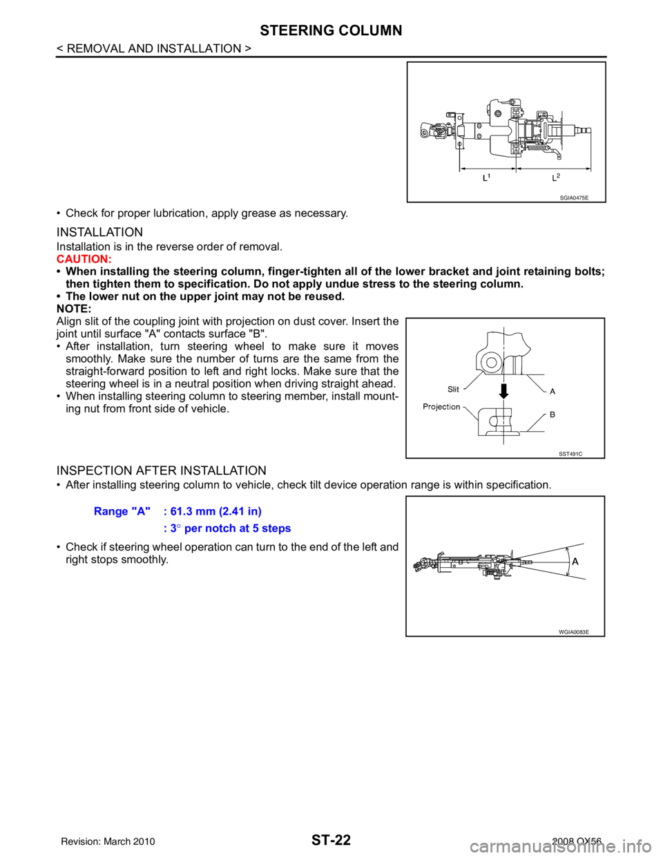
• Check for proper lubrication, apply grease as necessary.
INSTALLATION
Installation is in the reverse order of removal.
CAUTION:
• When installing the steering column, finger-tighten all of the lower bracket and joint retaining bolts;
then tighten them to specifi cation. Do not apply undue st ress to the steering column.
• The lower nut on the upper joint may not be reused.
NOTE:
Align slit of the coupling joint with projection on dust cover. Insert the
joint until surface "A" contacts surface "B".
• After installation, turn steering wheel to make sure it moves smoothly. Make sure the number of turns are the same from the
straight-forward position to left and right locks. Make sure that the
steering wheel is in a neutral position when driving straight ahead.
• When installing steering column to steering member, install mount- ing nut from front side of vehicle.
INSPECTION AFTER INSTALLATION
• After installing steering column to vehicle, chec k tilt device operation range is within specification.
• Check if steering wheel operation can turn to the end of the left and right stops smoothly.
SGIA0475E
SST491C
Range "A" : 61.3 mm (2.41 in)
: 3° per notch at 5 steps
WGIA0083E
Revision: March 2010 2008 QX56
Page 3547 of 4083

STR-18
< SERVICE DATA AND SPECIFICATIONS (SDS)
STARTER MOTOR
SERVICE DATA AND SPECIFICATIONS (SDS)
STARTER MOTOR
StarterINFOID:0000000001538878
ApplicationAll models
Manufacturer Mitsubishi
Model number M002T85571ZCKD
Ty p e Reduction gear type
System voltage 12V
No-load Terminal voltage
11V
Current Less than 145A
Revolution More than 3,300 rpm
Minimum diameter of commutator 31.4 mm (1.236 in)
Minimum length of brush 11.0 mm (0.433 in)
Brush spring tension 26.7-36.1 N (2.72 - 3.68 kg, 5.93 - 8.02 lb)
Clearance between pinion front edge and
pinion stopper 0.5 - 2.0 mm (0.020 - 0.079 in)
Revision: March 2010
2008 QX56
Page 3568 of 4083
A/T CONTROL SYSTEMTM-21
< FUNCTION DIAGNOSIS >
CEF
G H
I
J
K L
M A
B
TM
N
O P
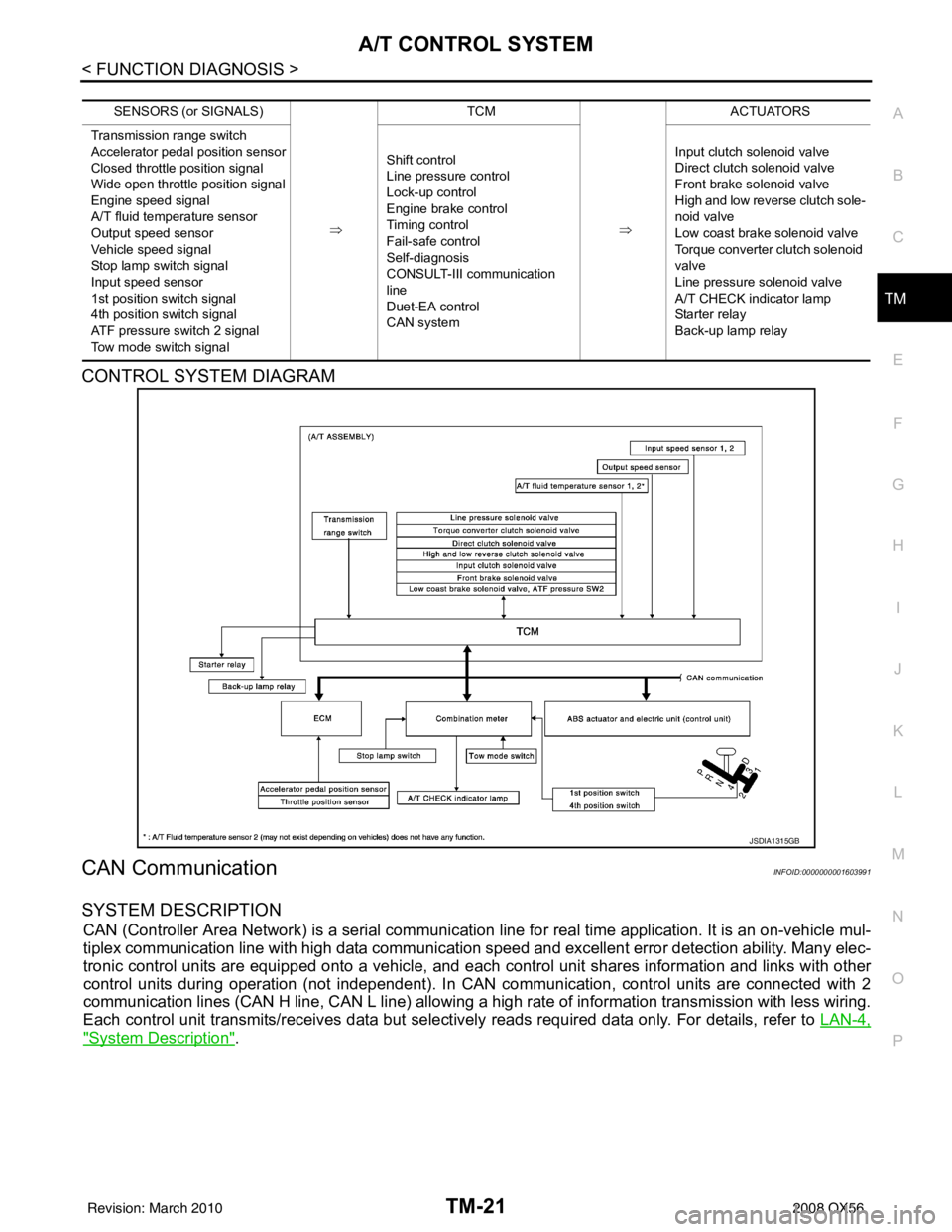
CONTROL SYSTEM DIAGRAM
CAN CommunicationINFOID:0000000001603991
SYSTEM DESCRIPTION
CAN (Controller Area Network) is a serial communication line for real time application. It is an on-vehicle mul-
tiplex communication line with high data communication speed and excellent error detection ability. Many elec-
tronic control units are equipped onto a vehicle, and each control unit shares information and links with other
control units during operation (not independent). In CAN communication, control units are connected with 2
communication lines (CAN H line, CAN L line) allowing a high rate of information transmission with less wiring.
Each control unit transmits/receives data but selectively reads required data only. For details, refer to LAN-4,
"System Description".
SENSORS (or SIGNALS)
⇒TCM
⇒ACTUATORS
Transmission range switch
Accelerator pedal position sensor
Closed throttle position signal
Wide open throttle position signal
Engine speed signal
A/T fluid temperature sensor
Output speed sensor
Vehicle speed signal
Stop lamp switch signal
Input speed sensor
1st position switch signal
4th position switch signal
ATF pressure switch 2 signal
Tow mode switch signal Shift control
Line pressure control
Lock-up control
Engine brake control
Timing control
Fail-safe control
Self-diagnosis
CONSULT-III co
mmunication
line
Duet-EA control
CAN system Input clutch solenoid valve
Direct clutch solenoid valve
Front brake solenoid valve
High and low reverse clutch sole-
noid valve
Low coast brake solenoid valve
Torque converter clutch solenoid
valve
Line pressure solenoid valve
A/T CHECK indicator lamp
Starter relay
Back-up lamp relay
JSDIA1315GB
Revision: March 2010
2008 QX56
Page 3576 of 4083
A/T SHIFT LOCK SYSTEMTM-29
< FUNCTION DIAGNOSIS >
CEF
G H
I
J
K L
M A
B
TM
N
O P
A/T SHIFT LOCK SYSTEM
System DescriptionINFOID:0000000001696150
• The selector lever cannot be shifted from “P” (Park) unless the brake pedal is applied and the ignition knob switch is turned to the “ON” position.
• The ignition knob switch cannot be returned to the “OFF” position unless the selector lever is placed in “P”
(Park).
• The shift lock mechanism is controlled by t he ON-OFF operation of the shift lock solenoid.
• The key switch and ignition knob switch lock mechanism is controlled by the ON-OFF operation of the key
lock solenoid.
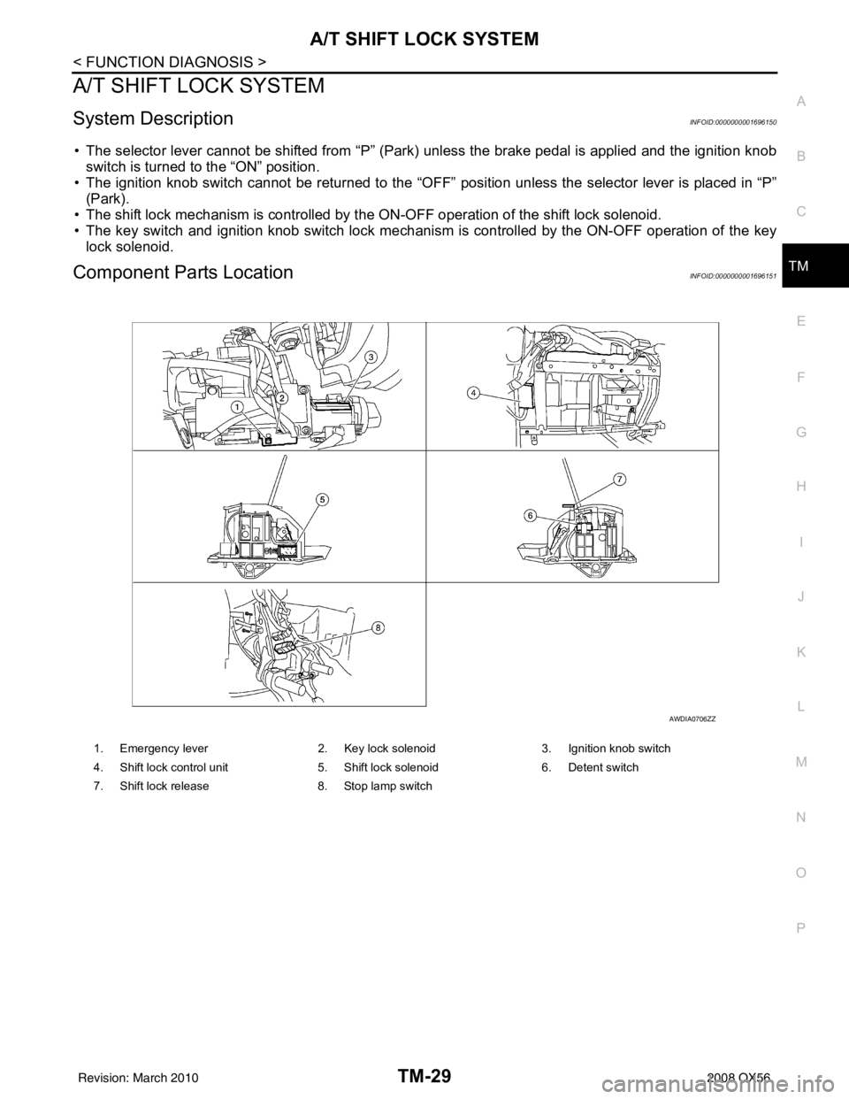
Component Parts LocationINFOID:0000000001696151
1. Emergency lever 2. Key lock solenoid3. Ignition knob switch
4. Shift lock control unit 5. Shift lock solenoid6. Detent switch
7. Shift lock release 8. Stop lamp switch
AWDIA0706ZZ
Revision: March 2010 2008 QX56
Page 3578 of 4083
ON BOARD DIAGNOSTIC (OBD) SYSTEMTM-31
< FUNCTION DIAGNOSIS >
CEF
G H
I
J
K L
M A
B
TM
N
O P
longer stored. Remember, only one set of freeze frame data can be stored in the ECM. The ECM has the fol-
lowing priorities to update the data.
Both 1st trip freeze frame data and freeze frame data (along with the DTC) are cleared when the ECM mem-
ory is erased.
HOW TO ERASE DTC
The diagnostic trouble code can be erased by CONSULT- III, GST or ECM DIAGNOSTIC TEST MODE as
described following.
• If the battery cable is disconnected, the diagnostic trouble code will be lost within 24 hours.
• When you erase the DTC, using CONSULT-III or GS T is easier and quicker than switching the mode
selector on the ECM.
The following emission-related diagnostic information is cleared from the ECM memory when erasing DTC
related to OBD-II. For details, refer to EC-42, "
Emission-related Diagnostic Information".
• Diagnostic trouble codes (DTC)
• 1st trip diagnostic trouble codes (1st trip DTC)
• Freeze frame data
• 1st trip freeze frame data
• System readiness test (SRT) codes
• Test values
HOW TO ERASE DTC (WITH CONSULT-III)
1. The emission related diagnostic information in the TCM and ECM can be er\
ased by selectioning "ALL
ERASE" in the "Description" of "F INAL CHECK" mode with CONSULT-III.
HOW TO ERASE DTC (WITH GST)
1. If the ignition switch stays “ON” after repair work, be sure to turn ignition switch “OFF” once. Wait at least
10 seconds and then turn it “ON” (engine stopped) again.
2. Select Mode 4 with the Generic Scan Tool (GST). For details refer to EC-72, "
Generic Scan Tool (GST)
Function".
HOW TO ERASE DTC (NO TOOLS)
1. Disconnect battery for 24 hours.
2. Reconnect battery.
Malfunction Indicator Lamp (MIL)INFOID:0000000001604006
DESCRIPTION
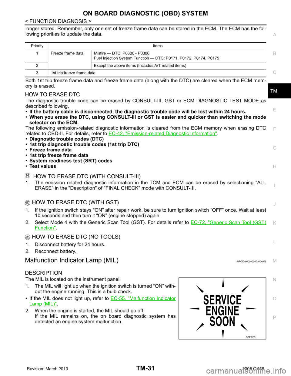
The MIL is located on the instrument panel.
1. The MIL will light up when the ignition switch is turned “ON” with-
out the engine running. This is a bulb check.
• If the MIL does not light up, refer to EC-55, "
Malfunction Indicator
Lamp (MIL)".
2. When the engine is start ed, the MIL should go off.
If the MIL remains on, the on board diagnostic system has
detected an engine system malfunction.
Priority Items
1 Freeze frame data Misfire — DTC: P0300 - P0306 Fuel Injection System Function — DTC: P0171, P0172, P0174, P0175
2 Except the above items (Includes A/T related items)
3 1st trip freeze frame data
SEF217U
Revision: March 2010 2008 QX56
Page 3581 of 4083
TM-34
< FUNCTION DIAGNOSIS >
DIAGNOSIS SYSTEM (TCM)
*1: Refer to EC-55, "Malfunction Indicator Lamp (MIL)".
*2:These malfunctions cannot be displayed MIL if another malfunction is assigned to MIL.
DATA MONITOR MODE
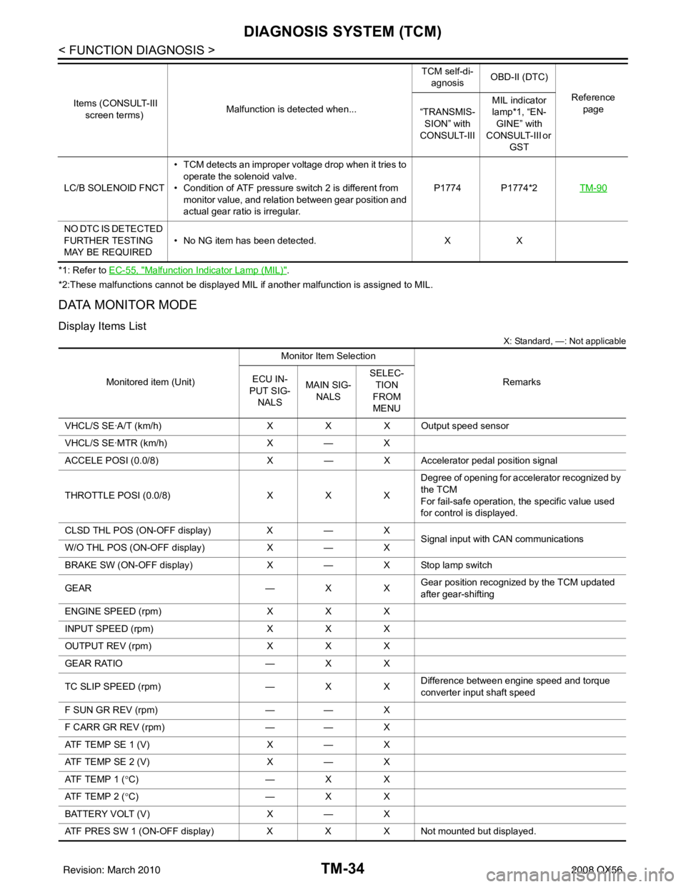
Display Items List
X: Standard, —: Not applicable
LC/B SOLENOID FNCT • TCM detects an improper voltage drop when it tries to
operate the solenoid valve.
• Condition of ATF pressure switch 2 is different from
monitor value, and relation between gear position and
actual gear ratio is irregular. P1774 P1774*2
TM-90
NO DTC IS DETECTED
FURTHER TESTING
MAY BE REQUIRED• No NG item has been detected.
XX
Items (CONSULT-III
screen terms) Malfunction is detected when... TCM self-di-
agnosis OBD-II (DTC)
Reference page
“TRANSMIS-
SION” with
CONSULT-III MIL indicator
lamp*1, “EN-
GINE” with
CONSULT-III or
GST
Monitored item (Unit) Monitor Item Selection
Remarks
ECU IN-
PUT SIG-
NALS MAIN SIG-
NALS SELEC-
TION
FROM
MENU
VHCL/S SE·A/T (km/h) XXX Output speed sensor
VHCL/S SE·MTR (km/h) X— X
ACCELE POSI (0.0/8) X— X Accelerator pedal position signal
THROTTLE POSI (0.0/8) XXXDegree of opening for accelerator recognized by
the TCM
For fail-safe operation, the specific value used
for control is displayed.
CLSD THL POS (ON-OFF display) X— X
Signal input with CAN communications
W/O THL POS (ON-OFF display) X— X
BRAKE SW (ON-OFF display) X— X Stop lamp switch
GEAR —XXGear position recognized by the TCM updated
after gear-shifting
ENGINE SPEED (rpm) XXX
INPUT SPEED (rpm) XXX
OUTPUT REV (rpm) XXX
GEAR RATIO —XX
TC SLIP SPEED (rpm) —XXDifference between engine speed and torque
converter input shaft speed
F SUN GR REV (rpm) —— X
F CARR GR REV (rpm) —— X
ATF TEMP SE 1 (V) X— X
ATF TEMP SE 2 (V) X— X
ATF TEMP 1 (° C) —XX
ATF TEMP 2 (° C) —XX
BATTERY VOLT (V) X— X
ATF PRES SW 1 (ON-OFF display) XXX Not mounted but displayed.
Revision: March 2010 2008 QX56