2008 INFINITI QX56 ECO mode
[x] Cancel search: ECO modePage 3631 of 4083
TM-84
< COMPONENT DIAGNOSIS >
P1762 DIRECT CLUTCH SOLENOID
P1762 DIRECT CLUTCH SOLENOID
DescriptionINFOID:0000000001604136
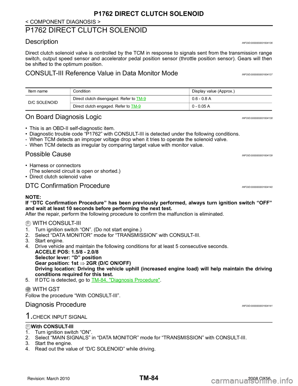
Direct clutch solenoid valve is controlled by the TCM in response to signals sent from the transmission range
switch, output speed sensor and accelerator pedal position sensor (throttle position sensor). Gears will then
be shifted to the optimum position.
CONSULT-III Reference Value in Data Monitor ModeINFOID:0000000001604137
On Board Diagn osis LogicINFOID:0000000001604138
• This is an OBD-II self-diagnostic item.
• Diagnostic trouble code “P1762” with CONSULT-III is detected under the following conditions.
- When TCM detects an improper voltage drop when it tries to operate the solenoid valve.
- When TCM detects as irregular by comparing target value with monitor value.
Possible CauseINFOID:0000000001604139
• Harness or connectors (The solenoid circuit is open or shorted.)
• Direct clutch solenoid valve
DTC Confirmation ProcedureINFOID:0000000001604140
NOTE:
If “DTC Confirmation Procedure” has been previously performed, always turn ignition switch “OFF”
and wait at least 10 seconds before performing the next test.
After the repair, perform the following proc edure to confirm the malfunction is eliminated.
WITH CONSULT-III
1. Turn ignition switch “ON”. (Do not start engine.)
2. Select “DATA MONITOR” mode for “TRANSMISSION” with CONSULT-III.
3. Start engine.
4. Drive vehicle and maintain the following conditions for at least 5 consecutive seconds. ACCELE POS: 1.5/8 - 2.0/8
Selector lever: “D” position
Gear position: 1st ⇒ 2GR (D/C ON/OFF)
Driving location: Driving the vehicle uphill (increased engine load) will help maintain the driving
conditions required for this test.
5. If DTC is detected, go to TM-84, "
Diagnosis Procedure".
WITH GST
Follow the procedure “With CONSULT-III”.
Diagnosis ProcedureINFOID:0000000001604141
1.CHECK INPUT SIGNAL
With CONSULT-III
1. Turn ignition switch “ON”.
2. Select “MAIN SIGNALS” in “DATA MONITO R” mode for “TRANSMISSION” with CONSULT-III.
3. Start the engine.
4. Read out the value of “D/C SOLENOID” while driving.
Item name Condition Display value (Approx.)
D/C SOLENOID Direct clutch disengaged. Refer to
TM-9
0.6 - 0.8 A
Direct clutch engaged. Refer to TM-9
0 - 0.05 A
Revision: March 2010 2008 QX56
Page 3633 of 4083
TM-86
< COMPONENT DIAGNOSIS >
P1767 HIGH AND LOW REVERSE CLUTCH SOLENOID
P1767 HIGH AND LOW REVERSE CLUTCH SOLENOID
DescriptionINFOID:0000000001604142
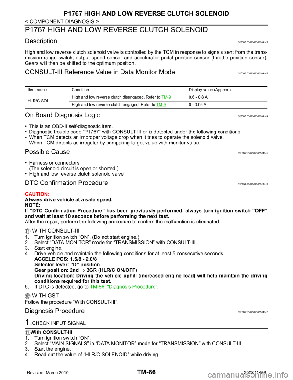
High and low reverse clutch solenoid valve is controlled by the TCM in response to signals sent from the trans-
mission range switch, output speed sensor and accelerato r pedal position sensor (throttle position sensor).
Gears will then be shifted to the optimum position.
CONSULT-III Reference Value in Data Monitor ModeINFOID:0000000001604143
On Board Diagn osis LogicINFOID:0000000001604144
• This is an OBD-II self-diagnostic item.
• Diagnostic trouble code “P1767” with CONSULT-III or is detected under the following conditions.
- When TCM detects an improper voltage drop when it tries to operate the solenoid valve.
- When TCM detects as irregular by comparing target value with monitor value.
Possible CauseINFOID:0000000001604145
• Harness or connectors
(The solenoid circuit is open or shorted.)
• High and low reverse clutch solenoid valve
DTC Confirmation ProcedureINFOID:0000000001604146
CAUTION:
Always drive vehicle at a safe speed.
NOTE:
If “DTC Confirmation Procedure” has been previously performed, always turn ignition switch “OFF”
and wait at least 10 seconds before performing the next test.
After the repair, perform the following proc edure to confirm the malfunction is eliminated.
WITH CONSULT-III
1. Turn ignition switch “ON”. (Do not start engine.)
2. Select “DATA MONITOR” mode for “TRANSMISSION” with CONSULT-III.
3. Start engine.
4. Drive vehicle and maintain the following conditions for at least 5 consecutive seconds.
ACCELE POS: 1.5/8 - 2.0/8
Selector lever: “D” position
Gear position: 2nd ⇒ 3GR (HLR/C ON/OFF)
Driving location: Driving the vehicle uphill (increased engine load) will help maintain the driving
conditions required for this test.
5. If DTC is detected, go to TM-86, "
Diagnosis Procedure".
WITH GST
Follow the procedure “With CONSULT-III”.
Diagnosis ProcedureINFOID:0000000001604147
1.CHECK INPUT SIGNAL
With CONSULT-III
1. Turn ignition switch “ON”.
2. Select “MAIN SIGNALS” in “DATA MONITO R” mode for “TRANSMISSION” with CONSULT-III.
3. Start the engine.
4. Read out the value of “HLR/C SOLENOID” while driving.
Item name Condition Display value (Approx.)
HLR/C SOL High and low reverse clutch disengaged. Refer to TM-9
0.6 - 0.8 A
High and low reverse clutch engaged. Refer to TM-9
0 - 0.05 A
Revision: March 2010 2008 QX56
Page 3635 of 4083
TM-88
< COMPONENT DIAGNOSIS >
P1772 LOW COAST BRAKE SOLENOID
P1772 LOW COAST BRAKE SOLENOID
DescriptionINFOID:0000000001604148
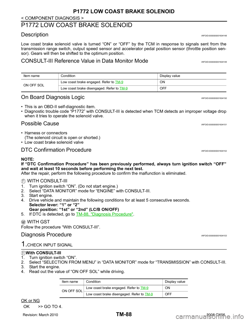
Low coast brake solenoid valve is turned “ON” or “OFF” by the TCM in response to signals sent from the
transmission range switch, output speed sensor and accele rator pedal position sensor (throttle position sen-
sor). Gears will then be shifted to the optimum position.
CONSULT-III Reference Value in Data Monitor ModeINFOID:0000000001604149
On Board Diagn osis LogicINFOID:0000000001604150
• This is an OBD-II self-diagnostic item.
• Diagnostic trouble code “P1772” with CONSULT-III is detected when TCM detects an improper voltage drop
when it tries to operate the solenoid valve.
Possible CauseINFOID:0000000001604151
• Harness or connectors(The solenoid circuit is open or shorted.)
• Low coast brake solenoid valve
DTC Confirmation ProcedureINFOID:0000000001604152
NOTE:
If “DTC Confirmation Procedure” has been previously performed, always turn ignition switch “OFF”
and wait at least 10 seconds before performing the next test.
After the repair, perform the following proc edure to confirm the malfunction is eliminated.
WITH CONSULT-III
1. Turn ignition switch “ON”. (Do not start engine.)
2. Select “DATA MONITOR” mode for “ENGINE” with CONSULT-III.
3. Start engine.
4. Drive vehicle and maintain the following conditions for at least 5 consecutive seconds.
Selector lever: “1” or “2”
Gear position: “1st” or “2nd” (LC/B ON/OFF)
5. If DTC is detected, go to TM-88, "
Diagnosis Procedure".
WITH GST
Follow the procedure “With CONSULT-III”.
Diagnosis ProcedureINFOID:0000000001604153
1.CHECK INPUT SIGNAL
With CONSULT-III
1. Turn ignition switch “ON”.
2. Select “SELECTION FROM MENU” in “DATA MONI TOR” mode for “TRANSMISSION” with CONSULT-III.
3. Start the engine.
4. Read out the value of “ON OFF SOL” while driving.
OK or NG
OK >> GO TO 4.
Item name Condition Display value
ON OFF SOL Low coast brake engaged. Refer to
TM-9
ON
Low coast brake disengaged. Refer to TM-9
OFF
Item name Condition Display value
ON OFF SOL Low coast brake engaged. Refer to TM-9
ON
Low coast brake disengaged. Refer to TM-9
OFF
Revision: March 2010 2008 QX56
Page 3637 of 4083
TM-90
< COMPONENT DIAGNOSIS >
P1774 LOW COAST BRAKE SOLENOID
P1774 LOW COAST BRAKE SOLENOID
DescriptionINFOID:0000000001604154
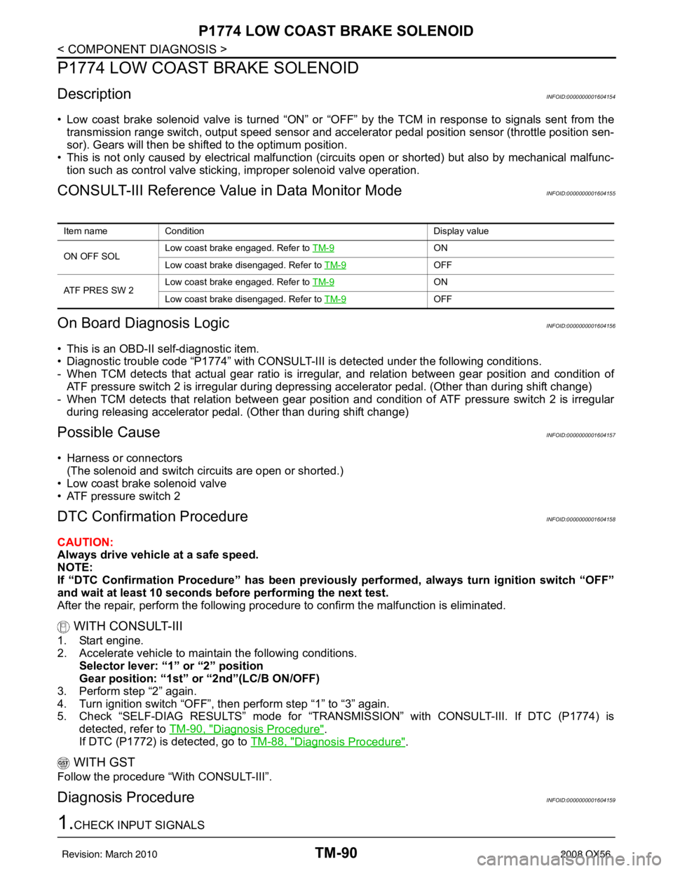
• Low coast brake solenoid valve is turned “ON” or “OFF” by the TCM in response to signals sent from the
transmission range switch, output speed sensor and accele rator pedal position sensor (throttle position sen-
sor). Gears will then be shifted to the optimum position.
• This is not only caused by electrical malfunction (circuits open or shorted) but also by mechanical malfunc- tion such as control valve sticking, improper solenoid valve operation.
CONSULT-III Reference Value in Data Monitor ModeINFOID:0000000001604155
On Board Diagn osis LogicINFOID:0000000001604156
• This is an OBD-II self-diagnostic item.
• Diagnostic trouble code “P1774” with CONSULT-III is detected under the following conditions.
- When TCM detects that actual gear ratio is irregular, and relation between gear position and condition of
ATF pressure switch 2 is irregular during depressing accelerator pedal. (Other than during shift change)
- When TCM detects that relation between gear position and condition of ATF pressure switch 2 is irregular
during releasing accelerator pedal. (Other than during shift change)
Possible CauseINFOID:0000000001604157
• Harness or connectors
(The solenoid and switch circuits are open or shorted.)
• Low coast brake solenoid valve
• ATF pressure switch 2
DTC Confirmation ProcedureINFOID:0000000001604158
CAUTION:
Always drive vehicle at a safe speed.
NOTE:
If “DTC Confirmation Procedure” has been previously performed, always turn ignition switch “OFF”
and wait at least 10 seconds before performing the next test.
After the repair, perform the following proc edure to confirm the malfunction is eliminated.
WITH CONSULT-III
1. Start engine.
2. Accelerate vehicle to maintain the following conditions.
Selector lever: “1” or “2” position
Gear position: “1st” or “2nd”(LC/B ON/OFF)
3. Perform step “2” again.
4. Turn ignition switch “OFF”, then perform step “1” to “3” again.
5. Check “SELF-DIAG RESULTS” mode for “TRANSMISSION” with CONSULT-III. If DTC (P1774) is detected, refer to TM-90, "
Diagnosis Procedure".
If DTC (P1772) is detected, go to TM-88, "
Diagnosis Procedure".
WITH GST
Follow the procedure “With CONSULT-III”.
Diagnosis ProcedureINFOID:0000000001604159
1.CHECK INPUT SIGNALS
Item nameCondition Display value
ON OFF SOL Low coast brake engaged. Refer to
TM-9
ON
Low coast brake disengaged. Refer to TM-9
OFF
ATF PRES SW 2 Low coast brake engaged. Refer to
TM-9
ON
Low coast brake disengaged. Refer to TM-9
OFF
Revision: March 2010 2008 QX56
Page 3641 of 4083

TM-94
< COMPONENT DIAGNOSIS >
CLOSED THROTTLE POSITION AND WIDE OPEN THROTTLE POSITION CIR-
CUIT
CLOSED THROTTLE POSITION AND WIDE OPEN THROTTLE POSITION
CIRCUIT
CONSULT-III Reference Value in Data Monitor ModeINFOID:0000000001604161
Diagnosis ProcedureINFOID:0000000001604162
1.CHECK CAN COMMUNICATION LINE
Perform the self-diagnosis. Refer to TM-32, "
CONSULT-III Function (TRANSMISSION)".
Is a malfunction in the CAN communication indicated in the results?
YES >> Check CAN communication line. Refer to TM-38.
NO >> GO TO 2.
2.CHECK THROTTLE POSI TION SIGNAL CIRCUIT
With CONSULT-III
1. Turn ignition switch “ON”. (Do not start engine.)
2. Select “ECU INPUT SIGNALS” in “DATA MONI TOR” mode for “TRANSMISSION” with CONSULT-III.
3. Depress accelerator pedal and read out the value of “CLSD THL POS” and “W/O THL POS”.
OK or NG
OK >> INSPECTION END
NG >> Check the following items. If NG, repair or replace damaged parts. • Perform the self-diagnosis for “ENGINE” with CONSULT-III.
• Open circuit or short to ground or shor t to power in harness or connectors.
• Pin terminals for damage or loos e connection with harness connector.
Item nameCondition Display value
CLSD THL POS Released accelerator pedal.
ON
Fully depressed accelerator pedal. OFF
W/O THL POS Fully depressed accelerator pedal.
ON
Released accelerator pedal. OFF
Accelerator Pedal OperationMonitor Item
CLSD THL POS W/O THL POS
Released ONOFF
Fully depressed OFFON
Revision: March 2010 2008 QX56
Page 3662 of 4083

TCM
TM-115
< ECU DIAGNOSIS >
C EF
G H
I
J
K L
M A
B
TM
N
O P
Even when the electronic circuits are normal, under s pecial conditions (for example, when slamming on the
brake with the wheels spinning drastically and stopping the tire rotation), the transmission can go into fail-safe
mode. If this happens, switch “OFF” the ignition switch for 10 seconds, then switch it “ON” again to return to
the normal shift pattern. Therefore, the customer's vehicle has returned to normal, so handle according to the
“diagnostics flow” (Refer to TM-5, "
Work Flow").
FAIL-SAFE FUNCTION
If any malfunction occurs in a sensor or solenoid, th is function controls the A/T to mark driving possible.
Output Speed Sensor
• Signals are input from two systems - from output s peed sensor installed on the transmission and from com-
bination meter so normal driving is possible even if t here is a malfunction in one of the systems. And if output
speed sensor has unusual cases, 5GR is prohibited.
Accelerator Pedal Position Sensor
• If there is a malfunction in one of the systems, the accelerator opening angle is controlled by ECM according
to a pre-determined accelerator angle to make driving possible. And if there are malfunctions in tow sys-
tems, the engine speed is fixed by ECM to a pre-determined engine speed to make driving possible.
Throttle Position Sensor
• If there is a malfunction in one of the systems, the accelerator opening angle is controlled by ECM according
to a pre-determined accelerator angle to make driving possible. And if there are malfunctions in tow sys-
tems, the accelerator opening angle is controlled by the idle signal sent from the ECM which is based on
input indicating either idle condition or off-idle condition (pre-determined accelerator opening) in order to
make driving possible.
Transmission Range Switch
• In the unlikely event that a malfunction signal enters t he TCM, the position indicator is switched “OFF”, the
starter relay is switched “OFF” (starter starting is disabled), the back-up lamp relay switched “OFF” (back-up
lamp is OFF) and the position is fixed to the “D” range to make driving possible.
Starter Relay
• The starter relay is switched “OFF”. (Starter starting is disabled.)
Interlock
• If there is an interlock judgment malfunction, the tr ansmission is fixed in 2GR to make driving possible.
NOTE:
When the vehicle is driven fixed in 2GR, a inpu t speed sensor malfunction is displayed, but this is
not a input speed sensor malfunction.
• When the interlock is detected at the 3GR or more, it is locked at the 2GR.
1st Engine Braking
• When there is an 1st engine brake judgment malfunction, the low coast brake solenoid is switched “OFF” to
avoid the engine brake operation.
Line Pressure Solenoid
• The solenoid is switched “OFF” and the line pressure is set to the maximum hydraulic pressure to make driv- ing possible.
Torque Converter Clutch Solenoid
• The solenoid is switched “OFF” to release the lock-up.
Low Coast Brake Solenoid
• When a (electrical or functional) malfunction occurs, in order to make driving possible, the engine brake is
not applied in 1GR and 2GR.
Input Clutch Solenoid
• If a (electrical or functional) malfunction occurs with the solenoid either “ON” or “OFF”, the transmission is
held in 4th gear to make driving possible.
Direct Clutch Solenoid
• If a (electrical or functional) malfunction occurs with the solenoid either “ON” or “OFF”, the transmission is
held in 4GR to make driving possible.
Front Brake Solenoid
• If a (electrical or functional) malfunction occurs with the solenoid “ON”, in order to make driving possible, the
A/T is held in 5GR; if the solenoid is OFF, 4GR.
Revision: March 2010 2008 QX56
Page 3720 of 4083

PRECAUTIONSTM-173
< PRECAUTION >
CEF
G H
I
J
K L
M A
B
TM
N
O P
PRECAUTION
PRECAUTIONS
Precaution for Supplemental Restraint System (SRS) "AIR BAG" and "SEAT BELT
PRE-TENSIONER"
INFOID:0000000006054118
The Supplemental Restraint System such as “AIR BAG” and “SEAT BELT PRE-TENSIONER”, used along
with a front seat belt, helps to reduce the risk or severi ty of injury to the driver and front passenger for certain
types of collision. This system includes seat belt switch inputs and dual stage front air bag modules. The SRS
system uses the seat belt switches to determine the front air bag deployment, and may only deploy one front
air bag, depending on the severity of a collision and w hether the front occupants are belted or unbelted.
Information necessary to service the system safely is included in the SR and SB section of this Service Man-
ual.
WARNING:
• To avoid rendering the SRS inoper ative, which could increase the risk of personal injury or death in
the event of a collision which would result in air bag inflation, all maintenance must be performed by
an authorized NISSAN/INFINITI dealer.
• Improper maintenance, including in correct removal and installation of the SRS, can lead to personal
injury caused by unintentional act ivation of the system. For removal of Spiral Cable and Air Bag
Module, see the SR section.
• Do not use electrical test equipm ent on any circuit related to the SRS unless instructed to in this
Service Manual. SRS wiring harnesses can be identi fied by yellow and/or orange harnesses or har-
ness connectors.
PRECAUTIONS WHEN USING POWER TOOLS (AIR OR ELECTRIC) AND HAMMERS
WARNING:
• When working near the Airbag Diagnosis Sensor Un it or other Airbag System sensors with the Igni-
tion ON or engine running, DO NOT use air or el ectric power tools or strike near the sensor(s) with a
hammer. Heavy vibration could activate the sensor( s) and deploy the air bag(s), possibly causing
serious injury.
• When using air or electric power tools or hammers, always switch the Ignition OFF, disconnect the battery, and wait at least 3 minutes before performing any service.
Precaution Necessary for Steering Wheel Rotation After Battery Disconnect
INFOID:0000000004857582
NOTE:
• This Procedure is applied only to models with Intelligent Key system and NATS (NISSAN ANTI-THEFT SYS-
TEM).
• Remove and install all control units after disconnecti ng both battery cables with the ignition knob in the
″ LOCK ″ position.
• Always use CONSULT-III to perform self-diagnosis as a part of each function inspection after finishing work.
If DTC is detected, perform trouble diagnosis according to self-diagnostic results.
For models equipped with the Intelligent Key system and NATS , an electrically controlled steering lock mech-
anism is adopted on the key cylinder.
For this reason, if the battery is disconnected or if the battery is discharged, the steering wheel will lock and
steering wheel rotation will become impossible.
If steering wheel rotation is required when battery power is interrupted, follow the procedure below before
starting the repair operation.
OPERATION PROCEDURE
1. Connect both battery cables. NOTE:
Supply power using jumper cables if battery is discharged.
2. Use the Intelligent Key or mechanical key to turn the ignition switch to the ″ACC ″ position. At this time, the
steering lock will be released.
3. Disconnect both battery cables. The steering lock will remain released and the steering wheel can be
rotated.
4. Perform the necessary repair operation.
Revision: March 2010 2008 QX56
Page 3721 of 4083
TM-174
< PRECAUTION >
PRECAUTIONS
5. When the repair work is completed, return the ignition switch to the ″LOCK ″ position before connecting
the battery cables. (At this time, the steering lock mechanism will engage.)
6. Perform a self-diagnosis check of a ll control units using CONSULT-III.
Precaution for On Board Diagnosis (OBD) System of A/T and EngineINFOID:0000000001531485
The ECM has an on board diagnostic system. It will light up the malfunction indicator lamp (MIL) to warn the
driver of a malfunction causing emission deterioration.
CAUTION:
• Be sure to turn the ignition switch “OFF” and disconnect the negative battery cable before any repair
or inspection work. The open/short circuit of related switches, sensors, solenoid valves, etc. Will
cause the MIL to light up.
• Be sure to connect and lock the connectors secure ly after work. A loose (unlocked) connector will
cause the MIL to light up due to an open circuit. (Be sure the connector is free from water, grease,
dirt, bent terminals, etc.)
• Be sure to route and secure th e harnesses properly after work. Interference of the harness with a
bracket, etc. May cause the MIL to light up due to a short circuit.
• Be sure to connect rubber tubes properly afte r work. A misconnected or disconnected rubber tube
may cause the MIL to light up due to a malfunction of the EGR system or fuel injection system, etc.
• Be sure to erase the unnecessary malfunction informa tion (repairs completed) from the TCM and
ECM before returning the vehicle to the customer.
PrecautionINFOID:0000000001531486
NOTE:
If any malfunctions occur in the RE5R05A model tr ansmission, replace the entire transmission assem-
bly.
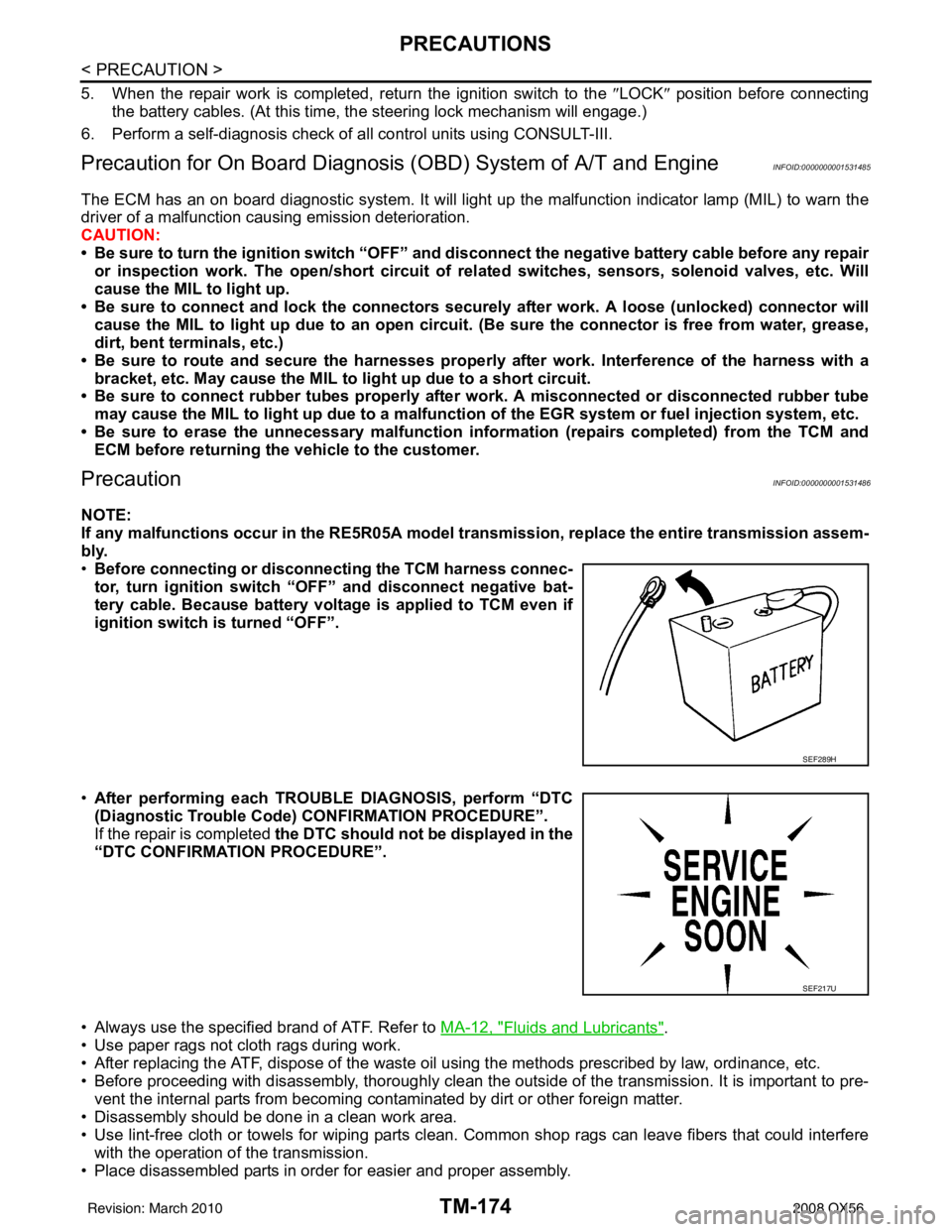
• Before connecting or disconn ecting the TCM harness connec-
tor, turn ignition switch “O FF” and disconnect negative bat-
tery cable. Because battery voltage is applied to TCM even if
ignition switch is turned “OFF”.
• After performing each TROUBLE DIAGNOSIS, perform “DTC
(Diagnostic Trouble Code) CONFIRMATION PROCEDURE”.
If the repair is completed the DTC should not be displayed in the
“DTC CONFIRMATION PROCEDURE”.
• Always use the specified brand of ATF. Refer to MA-12, "
Fluids and Lubricants".
• Use paper rags not cloth rags during work.
• After replacing the ATF, dispose of the waste oil using the methods prescribed by law, ordinance, etc.
• Before proceeding with disassembly, thoroughly clean the outside of the transmission. It is important to pre- vent the internal parts from becoming cont aminated by dirt or other foreign matter.
• Disassembly should be done in a clean work area.
• Use lint-free cloth or towels for wiping parts clean. Common shop rags can leave fibers that could interfere
with the operation of the transmission.
• Place disassembled parts in order for easier and proper assembly.
SEF289H
SEF217U
Revision: March 2010 2008 QX56