2008 INFINITI QX56 ECO mode
[x] Cancel search: ECO modePage 3823 of 4083

TM-276
< DISASSEMBLY AND ASSEMBLY >
ASSEMBLY
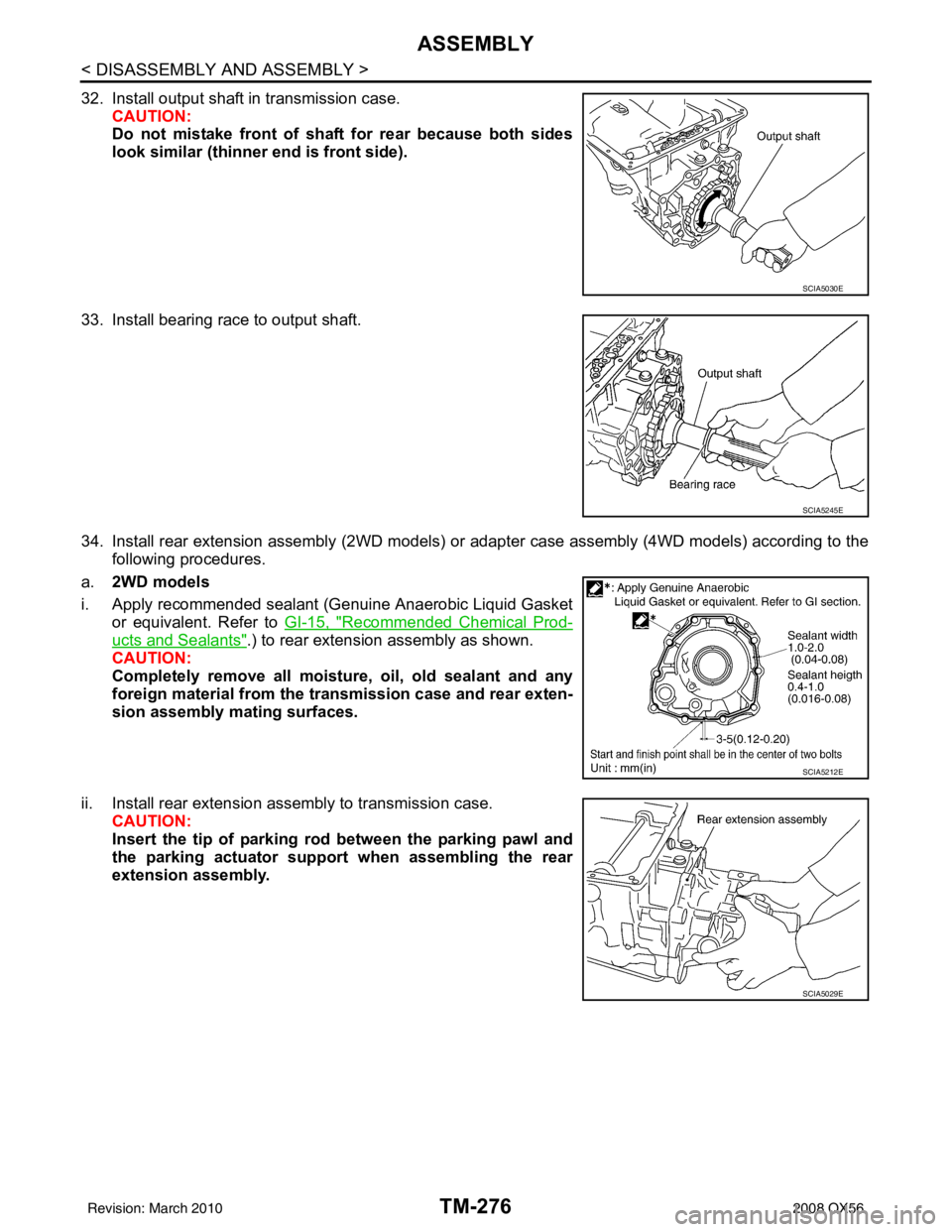
32. Install output shaft in transmission case.CAUTION:
Do not mistake front of shaft for rear because both sides
look similar (thinner end is front side).
33. Install bearing race to output shaft.
34. Install rear extension assembly (2WD models) or adapter case assembly (4WD models) according to the following procedures.
a. 2WD models
i. Apply recommended sealant (Genuine Anaerobic Liquid Gasket or equivalent. Refer to GI-15, "
Recommended Chemical Prod-
ucts and Sealants".) to rear extension assembly as shown.
CAUTION:
Completely remove all moisture, oil, old sealant and any
foreign material from the tr ansmission case and rear exten-
sion assembly mating surfaces.
ii. Install rear extension assembly to transmission case. CAUTION:
Insert the tip of parking rod between the parking pawl and
the parking actuator support when assembling the rear
extension assembly.
SCIA5030E
SCIA5245E
SCIA5212E
SCIA5029E
Revision: March 2010 2008 QX56
Page 3838 of 4083

SERVICE DATA AND SPECIFICATIONS (SDS)TM-291
< SERVICE DATA AND SPECIFICATIONS (SDS)
CEF
G H
I
J
K L
M A
B
TM
N
O P
SERVICE DATA AND SPECIFICATIONS (SDS)
SERVICE DATA AND SPECIFICATIONS (SDS)
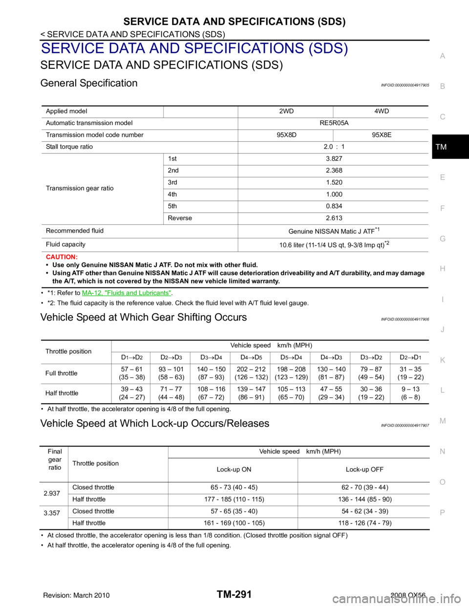
General SpecificationINFOID:0000000004917905
• *1: Refer to MA-12, "Fluids and Lubricants".
• *2: The fluid capacity is the reference value. Check the fluid level with A/T fluid level gauge.
Vehicle Speed at Which Gear Shifting OccursINFOID:0000000004917906
• At half throttle, the accelerator opening is 4/8 of the full opening.
Vehicle Speed at Which Lock-up Occurs/ReleasesINFOID:0000000004917907
• At closed throttle, the accelerator opening is less than 1/8 condition. (Closed throttle position signal OFF)
• At half throttle, the accelerator opening is 4/8 of the full opening. Applied model
2WD4WD
Automatic transmission model RE5R05A
Transmission model code number 95X8D95X8E
Stall torque ratio 2.0 : 1
Transmission gear ratio 1st
3.827
2nd 2.368
3rd 1.520
4th 1.000
5th 0.834
Reverse 2.613
Recommended fluid Genuine NISSAN Matic J ATF
*1
Fluid capacity10.6 liter (11-1/4 US qt, 9-3/8 Imp qt)*2
CAUTION:
• Use only Genuine NISSAN Matic J ATF. Do not mix with other fluid.
• Using ATF other than Genuine NISSAN Matic J ATF will cause deterioration driveability and A/ T durability, and may damage
the A/T, which is not covered by the NISSAN new vehicle limited warranty.
Throttle position Vehicle speed km/h (MPH)
D1→D2D2→ D3D3→D4D4→D5D5→D4D4→D3D3→D2D2→D1
Full throttle 57 – 61
(35 – 38) 93 – 101
(58 – 63) 140 – 150
(87 – 93) 202 – 212
(126 – 132) 198 – 208
(123 – 129) 130 – 140
(81 – 87) 79 – 87
(49 – 54) 31 – 35
(19 – 22)
Half throttle 39 – 43
(24 – 27) 71 – 77
(44 – 48) 108 – 116
(67 – 72) 139 – 147
(86 – 91) 105 – 113
(65 – 70) 47 – 55
(29 – 34) 30 – 36
(19 – 22) 9 – 13
(6 – 8)
Final gear ratio Throttle position Vehicle speed km/h (MPH)
Lock-up ON Lock-up OFF
2.937 Closed throttle
65 - 73 (40 - 45) 62 - 70 (39 - 44)
Half throttle 177 - 185 (110 - 115) 136 - 144 (85 - 90)
3.357 Closed throttle
57 - 65 (35 - 40) 54 - 62 (34 - 39)
Half throttle 161 - 169 (100 - 105) 118 - 126 (74 - 79)
Revision: March 2010 2008 QX56
Page 3839 of 4083

TM-292
< SERVICE DATA AND SPECIFICATIONS (SDS)
SERVICE DATA AND SPECIFICATIONS (SDS)
Stall Speed
INFOID:0000000004917908
Line PressureINFOID:0000000004917909
A/T Fluid Temperature SensorINFOID:0000000004917910
Input Speed SensorINFOID:0000000004917911
Output Speed SensorINFOID:0000000004917912
Reverse BrakeINFOID:0000000004917913
Total End PlayINFOID:0000000004917914
BEARING RACE FOR ADJUSTING TOTAL END PLAY
Stall speed 2,700 – 3,000 rpm
Engine speedLine pressure kPa (kg/cm2, psi)
“R” position “D” position
At idle speed 425 – 465 (4.3 – 4.7, 62 – 67) 379 – 428 (3.9 – 4.4, 55 – 62)
At stall speed 1,605 – 1,950 (16.4 – 19.9, 233 – 283) 1,310 – 1,500 (13.4 – 15.3, 190 – 218)
NameCondition CONSULT-I II “DATA MONITOR” (Approx.) (V) Resistance (Approx.) (k Ω)
ATF TEMP SE 1 0
°C (32 °F) 3.3 15
20 °C (68 °F) 2.7 6.5
80 °C (176 °F) 0.9 0.9
Name ConditionData (Approx.)
Input speed sensor 1 When running at 50 km/h (31 MPH) in 4th speed witch the closed throttle position
signal OFF.
1.3 kHz
Input speed sensor 2 When running at 20 km/h (12 MPH) in 1st speed witch the closed throttle position
signal OFF.
Name
ConditionData (Approx.)
Output speed sensor When running at 20 km/h (12 MPH). 185 Hz
Model code number 97X2E, 97X3A
Number of drive plates 6
Number of driven plates 6
Clearance mm (in) Standard 0.7 – 1.1 (0.028 – 0.043)
Thickness of retaining plates Thickness mm (in)
4.2 (0.165)
4.4 (0.173)
4.6 (0.181)
4.8 (0.189)
5.0 (0.197)
5.2 (0.205)
Total end play mm (in) 0.25 – 0.55 (0.0098 – 0.0217)
Revision: March 2010 2008 QX56
Page 3842 of 4083

VTL-2
< PRECAUTION >
PRECAUTIONS
PRECAUTION
PRECAUTIONS
Precaution for Supplemental Restraint System (SRS) "AIR BAG" and "SEAT BELT
PRE-TENSIONER"
INFOID:0000000004884177
The Supplemental Restraint System such as “A IR BAG” and “SEAT BELT PRE-TENSIONER”, used along
with a front seat belt, helps to reduce the risk or severity of injury to the driver and front passenger for certain
types of collision. This system includes seat belt switch inputs and dual stage front air bag modules. The SRS
system uses the seat belt switches to determine the front air bag deployment, and may only deploy one front
air bag, depending on the severity of a collision and w hether the front occupants are belted or unbelted.
Information necessary to service the system safely is included in the SR and SB section of this Service Man-
ual.
WARNING:
• To avoid rendering the SRS inopera tive, which could increase the risk of personal injury or death in
the event of a collision which would result in air bag inflation, all maintenance must be performed by
an authorized NISSAN/INFINITI dealer.
• Improper maintenance, including in correct removal and installation of the SRS, can lead to personal
injury caused by unintent ional activation of the system. For re moval of Spiral Cable and Air Bag
Module, see the SR section.
• Do not use electrical test equipmen t on any circuit related to the SRS unless instructed to in this
Service Manual. SRS wiring harn esses can be identified by yellow and/or orange harnesses or har-
ness connectors.
PRECAUTIONS WHEN USING POWER TOOLS (AIR OR ELECTRIC) AND HAMMERS
WARNING:
• When working near the Airbag Diagnosis Sensor Unit or other Airbag System sensors with the Igni-
tion ON or engine running, DO NOT use air or electri c power tools or strike near the sensor(s) with a
hammer. Heavy vibration could activate the sensor( s) and deploy the air bag(s), possibly causing
serious injury.
• When using air or electric power tools or hammers , always switch the Ignition OFF, disconnect the
battery, and wait at least 3 minu tes before performing any service.
Precaution Necessary for Steering W heel Rotation After Battery Disconnect
INFOID:0000000004884178
NOTE:
• This Procedure is applied only to models with Intelligent Key system and NATS (NISSAN ANTI-THEFT SYS-
TEM).
• Remove and install all control units after disconnecting both battery cables with the ignition knob in the
″LOCK ″ position.
• Always use CONSULT-III to perform self-diagnosis as a part of each function inspection after finishing work.
If DTC is detected, perform trouble diagnosis according to self-diagnostic results.
For models equipped with the Intelligent Key system and NATS, an electrically controlled steering lock mech-
anism is adopted on the key cylinder.
For this reason, if the battery is disconnected or if the battery is discharged, the steering wheel will lock and
steering wheel rotation will become impossible.
If steering wheel rotation is required when battery pow er is interrupted, follow the procedure below before
starting the repair operation.
OPERATION PROCEDURE
1. Connect both battery cables. NOTE:
Supply power using jumper cables if battery is discharged.
2. Use the Intelligent Key or mechanical key to turn the ignition switch to the ″ACC ″ position. At this time, the
steering lock will be released.
3. Disconnect both battery cables. The steering lock will remain released and the steering wheel can be rotated.
4. Perform the necessary repair operation.
Revision: March 2010 2008 QX56
Page 3845 of 4083

IN-CABIN MICROFILTERVTL-5
< FUNCTION DIAGNOSIS >
C
DE
F
G H
J
K L
M A
B
VTL
N
O P
FUNCTION DIAGNOSIS
IN-CABIN MICROFILTER
DescriptionINFOID:0000000001516601
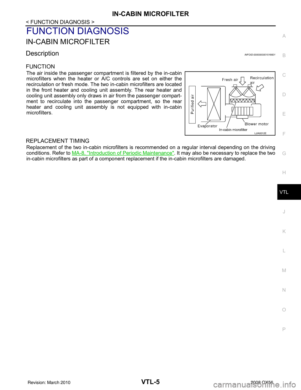
FUNCTION
The air inside the passenger compartment is filtered by the in-cabin
microfilters when the heater or A/C controls are set on either the
recirculation or fresh mode. The two in-cabin microfilters are located
in the front heater and cooling unit assembly. The rear heater and
cooling unit assembly only draws in air from the passenger compart-
ment to recirculate into the passenger compartment, so the rear
heater and cooling unit assembly is not equipped with in-cabin
microfilters.
REPLACEMENT TIMING
Replacement of the two in-cabin microfilters is recommended on a regular interval depending on the driving
conditions. Refer to MA-8, "
Introduction of Periodic Maintenance". It may also be necessary to replace the two
in-cabin microfilters as part of a component r eplacement if the in-cabin microfilters are damaged.
LJIA0012E
Revision: March 2010 2008 QX56
Page 3889 of 4083

WCS-12
< FUNCTION DIAGNOSIS >
DIAGNOSIS SYSTEM (METER)
DIAGNOSIS SYSTEM (METER)
Diagnosis DescriptionINFOID:0000000004872660
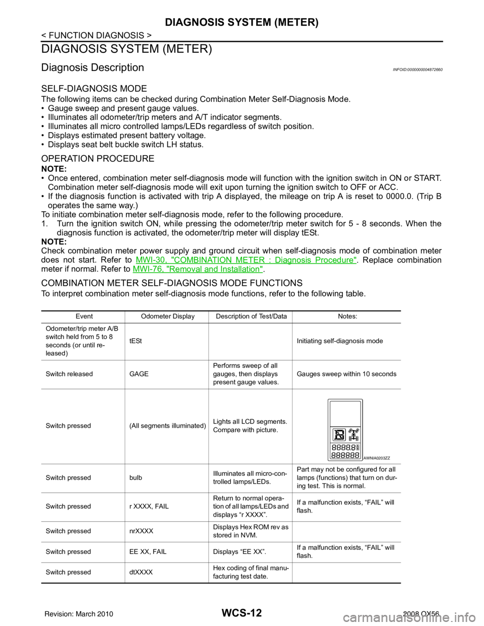
SELF-DIAGNOSIS MODE
The following items can be checked during Combination Meter Self-Diagnosis Mode.
• Gauge sweep and present gauge values.
• Illuminates all odometer/trip meters and A/T indicator segments.
• Illuminates all micro controlled lamps/LEDs regardless of switch position.
• Displays estimated present battery voltage.
• Displays seat belt buckle switch LH status.
OPERATION PROCEDURE
NOTE:
• Once entered, combination meter self-diagnosis mode will function with the ignition switch in ON or START.
Combination meter self-diagnosis mode will exit upon turning the ignition switch to OFF or ACC.
• If the diagnosis function is activated with trip A displa yed, the mileage on trip A is reset to 0000.0. (Trip B
operates the same way.)
To initiate combination meter self-diagnosis mode, refer to the following procedure.
1. Turn the ignition switch ON, while pressing the odometer/trip meter switch for 5 - 8 \
seconds. When the diagnosis function is activated, the odometer/trip meter will display tESt.
NOTE:
Check combination meter power supply and ground circuit when self-diagnosis mode of combination meter
does not start. Refer to MWI-30, "
COMBINATION METER : Diagnosis Procedure". Replace combination
meter if normal. Refer to MWI-76, "
Removal and Installation".
COMBINATION METER SELF-DIAGNOSIS MODE FUNCTIONS
To interpret combination meter self-diagnosis mode functions, refer to the following table.
EventOdometer Display Description of Test/Data Notes:
Odometer/trip meter A/B
switch held from 5 to 8
seconds (or until re-
leased) tESt
Initiating self-diagnosis mode
Switch released GAGE Performs sweep of all
gauges, then displays
present gauge values.Gauges sweep within 10 seconds
Switch pressed (All segments illuminated) Lights all LCD segments.
Compare with picture.
Switch pressed bulbIlluminates all micro-con-
trolled lamps/LEDs. Part may not be configured for all
lamps (functions) th
at turn on dur-
ing test. This is normal.
Switch pressed r XXXX, FAIL Return to normal opera-
tion of all lamps/LEDs and
displays “r XXXX”.If a malfunction exists, “FAIL” will
flash.
Switch pressed nrXXXX Displays Hex ROM rev as
stored in NVM.
Switch pressed EE XX, FAIL Displays “EE XX”.If a malfunction exists, “FAIL” will
flash.
Switch pressed dtXXXX Hex coding of final manu-
facturing test date.
AWNIA0203ZZ
Revision: March 2010
2008 QX56
Page 3926 of 4083

WCS
COMBINATION METERWCS-49
< ECU DIAGNOSIS >
C
DE
F
G H
I
J
K L
M B A
O P
DTC IndexINFOID:0000000004871171
Function Specifications
Speedometer
Zero indication.
Tachometer
Fuel gauge
Engine coolant temperature gauge
Engine oil pressure gauge
Voltage gauge
A/T oil temperature gauge
Illumination control
Meter illumination Change to nighttime mode when communication is lost.
Segment LCD Odometer
Freeze current indication.
A/T position Display turns off.
Buzzer Buzzer turns off.
Warning lamp/indicator lamp ABS warning lamp
Lamp turns on when communication is lost.
Brake warning lamp
VDC OFF indicator lamp
SLIP indicator lamp
A/T CHECK warning lamp
Lamp turns off when communication is lost.
Oil pressure/coolant temperature
warning lamp
Light indicator
Malfunction indicator lamp
Master warning lamp
Air bag warning lamp
High beam indicator
Turn signal indicator lamp
CRUISE indicator lamp
Driver and passenger seat belt warn-
ing lamp
Lamp turns off when disconnected.
Charge warning lamp
Security indicator lamp
4WD indicator lamp
ATP indicator lamp
CK SUSP warning lamp
Low tire pressu
re warning lamp Lamp will flash every second for 1 minute and then stay on con-
tinuously thereafter.
CONSULT-III display
MalfunctionReference
page
CAN COMM CIRC
[U1000] Malfunction is detected in CAN communication.
CAUTION:
Even when there is no ma
lfunction on CAN communication system, malfunction may be
misinterpreted when battery has low voltag e (when maintaining 7 - 8 V for about 2 sec-
onds) or 10A fuse [No. 19, located in the fuse block (J/B)] is disconnected. MWI-28
VEHICLE SPEED
CIRC
[B2205]Malfunction is detected when an erroneous speed signal is input.
CAUTION:
Even when there is no malfunction on speed signal system, malfunction may be misin-
terpreted when battery has low voltage (whe
n maintaining 7 - 8 V for about 2 seconds). MWI-29
Revision: March 2010
2008 QX56
Page 3945 of 4083

WCS-68
< PRECAUTION >
PRECAUTIONS
PRECAUTION
PRECAUTIONS
Precaution for Supplemental Restraint System (SRS) "AIR BAG" and "SEAT BELT
PRE-TENSIONER"
INFOID:0000000004857542
The Supplemental Restraint System such as “A IR BAG” and “SEAT BELT PRE-TENSIONER”, used along
with a front seat belt, helps to reduce the risk or severity of injury to the driver and front passenger for certain
types of collision. This system includes seat belt switch inputs and dual stage front air bag modules. The SRS
system uses the seat belt switches to determine the front air bag deployment, and may only deploy one front
air bag, depending on the severity of a collision and w hether the front occupants are belted or unbelted.
Information necessary to service the system safely is included in the SR and SB section of this Service Man-
ual.
WARNING:
• To avoid rendering the SRS inopera tive, which could increase the risk of personal injury or death in
the event of a collision which would result in air bag inflation, all maintenance must be performed by
an authorized NISSAN/INFINITI dealer.
• Improper maintenance, including in correct removal and installation of the SRS, can lead to personal
injury caused by unintent ional activation of the system. For re moval of Spiral Cable and Air Bag
Module, see the SR section.
• Do not use electrical test equipmen t on any circuit related to the SRS unless instructed to in this
Service Manual. SRS wiring harn esses can be identified by yellow and/or orange harnesses or har-
ness connectors.
PRECAUTIONS WHEN USING POWER TOOLS (AIR OR ELECTRIC) AND HAMMERS
WARNING:
• When working near the Airbag Diagnosis Sensor Unit or other Airbag System sensors with the Igni-
tion ON or engine running, DO NOT use air or electri c power tools or strike near the sensor(s) with a
hammer. Heavy vibration could activate the sensor( s) and deploy the air bag(s), possibly causing
serious injury.
• When using air or electric power tools or hammers , always switch the Ignition OFF, disconnect the
battery, and wait at least 3 minu tes before performing any service.
Precaution Necessary for Steering W heel Rotation After Battery Disconnect
INFOID:0000000004857543
NOTE:
• This Procedure is applied only to models with Intelligent Key system and NATS (NISSAN ANTI-THEFT SYS-
TEM).
• Remove and install all control units after disconnecting both battery cables with the ignition knob in the
″LOCK ″ position.
• Always use CONSULT-III to perform self-diagnosis as a part of each function inspection after finishing work.
If DTC is detected, perform trouble diagnosis according to self-diagnostic results.
For models equipped with the Intelligent Key system and NATS, an electrically controlled steering lock mech-
anism is adopted on the key cylinder.
For this reason, if the battery is disconnected or if the battery is discharged, the steering wheel will lock and
steering wheel rotation will become impossible.
If steering wheel rotation is required when battery pow er is interrupted, follow the procedure below before
starting the repair operation.
OPERATION PROCEDURE
1. Connect both battery cables. NOTE:
Supply power using jumper cables if battery is discharged.
2. Use the Intelligent Key or mechanical key to turn the ignition switch to the ″ACC ″ position. At this time, the
steering lock will be released.
3. Disconnect both battery cables. The steering lock will remain released and the steering wheel can be rotated.
4. Perform the necessary repair operation.
Revision: March 2010 2008 QX56