2008 INFINITI QX56 lock
[x] Cancel search: lockPage 1855 of 4083
EM-52
< ON-VEHICLE REPAIR >
TIMING CHAIN
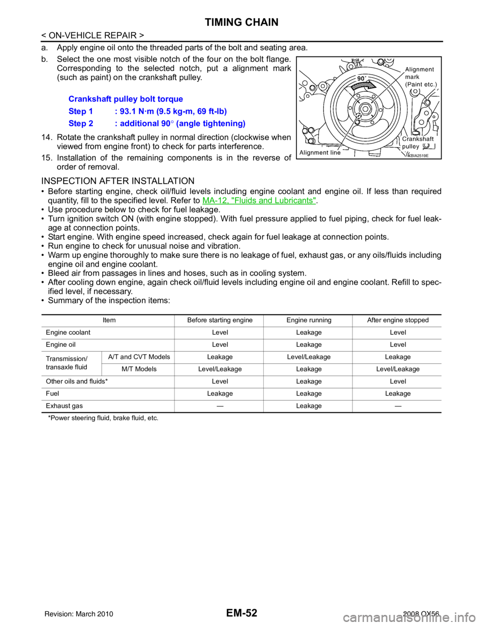
a. Apply engine oil onto the threaded parts of the bolt and seating area.
b. Select the one most visible notch of the four on the bolt flange.Corresponding to the selected notch, put a alignment mark
(such as paint) on the crankshaft pulley.
14. Rotate the crankshaft pulley in normal direction (clockwise when viewed from engine front) to check for parts interference.
15. Installation of the remaining components is in the reverse of order of removal.
INSPECTION AFTER INSTALLATION
• Before starting engine, check oil/fluid levels incl uding engine coolant and engine oil. If less than required
quantity, fill to the specified level. Refer to MA-12, "
Fluids and Lubricants".
• Use procedure below to check for fuel leakage.
• Turn ignition switch ON (with engine stopped). With fuel pressure applied to fuel piping, check for fuel leak- age at connection points.
• Start engine. With engine speed increased, che ck again for fuel leakage at connection points.
• Run engine to check for unusual noise and vibration.
• Warm up engine thoroughly to make sure there is no leakage of fuel, exhaust gas, or any oils/fluids including
engine oil and engine coolant.
• Bleed air from passages in lines and hoses, such as in cooling system.
• After cooling down engine, again check oil/fluid levels including engine oil and engine coolant. Refill to spec-
ified level, if necessary.
• Summary of the inspection items:
*Power steering fluid, brake fluid, etc.
Crankshaft pulley bolt torque
Step 1 : 93.1 N·m (9.5 kg-m, 69 ft-lb)
Step 2 : additional 90 ° (angle tightening)
KBIA2519E
Item Before starting engine Engine runningAfter engine stopped
Engine coolant LevelLeakage Level
Engine oil LevelLeakage Level
Transmission/
transaxle fluid A/T and CVT Models
LeakageLevel/Leakage Leakage
M/T Models Level/Leakage LeakageLevel/Leakage
Other oils and fluids* LevelLeakage Level
Fuel LeakageLeakage Leakage
Exhaust gas —Leakage —
Revision: March 2010 2008 QX56
Page 1857 of 4083
EM-54
< ON-VEHICLE REPAIR >
CAMSHAFT
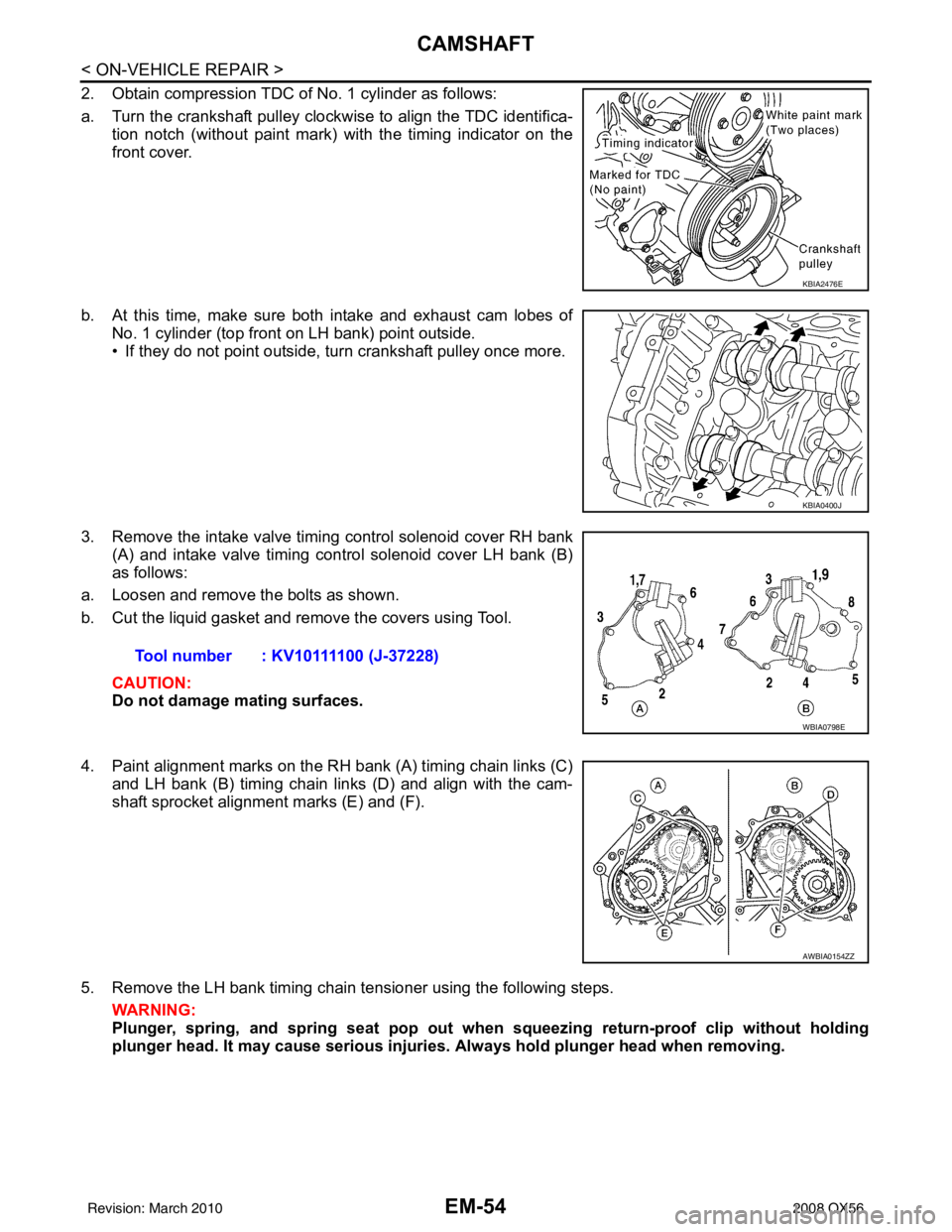
2. Obtain compression TDC of No. 1 cylinder as follows:
a. Turn the crankshaft pulley clockwise to align the TDC identifica-tion notch (without paint mark) with the timing indicator on the
front cover.
b. At this time, make sure both intake and exhaust cam lobes of No. 1 cylinder (top front on LH bank) point outside.
• If they do not point outside, turn crankshaft pulley once more.
3. Remove the intake valve timing control solenoid cover RH bank (A) and intake valve timing control solenoid cover LH bank (B)
as follows:
a. Loosen and remove the bolts as shown.
b. Cut the liquid gasket and remove the covers using Tool.
CAUTION:
Do not damage mating surfaces.
4. Paint alignment marks on the RH bank (A) timing chain links (C) and LH bank (B) timing chain links (D) and align with the cam-
shaft sprocket alignment marks (E) and (F).
5. Remove the LH bank timing chain tensioner using the following steps. WARNING:
Plunger, spring, and spring seat pop out when squeezing return-proof clip without holding
plunger head. It may cause serious injuries. Always hold plunger head when removing.
KBIA2476E
KBIA0400J
Tool number : KV10111100 (J-37228)
WBIA0798E
AWBIA0154ZZ
Revision: March 2010 2008 QX56
Page 1860 of 4083
CAMSHAFTEM-57
< ON-VEHICLE REPAIR >
C
DE
F
G H
I
J
K L
M A
EM
NP
O
11. Remove the camshaft.
12. Remove the valve lifters if necessary.
• Correctly identify location where each part is removed from. Keep parts organized to avoid mixing them
up.
INSPECTION AFTER REMOVAL
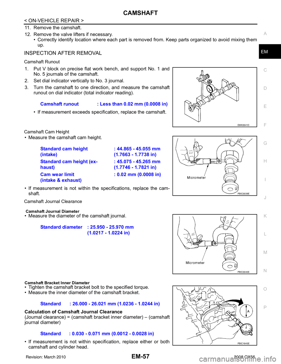
Camshaft Runout
1. Put V block on precise flat work bench, and support No. 1 and No. 5 journals of the camshaft.
2. Set dial indicator vertically to No. 3 journal.
3. Turn the camshaft to one direction, and measure the camshaft runout on dial indicator (total indicator reading).
• If measurement exceeds specif ication, replace the camshaft.
Camshaft Cam Height
• Measure the camshaft cam height.
• If measurement is not within the specifications, replace the cam-
shaft.
Camshaft Journal Clearance
Camshaft Journal Diameter
• Measure the diameter of the camshaft journal.
Camshaft Bracket Inner Diameter
• Tighten the camshaft bracket bolt to the specified torque.
• Measure the inner diameter of the camshaft bracket.
Calculation of Camshaft Journal Clearance
(Journal clearance) = (camshaft bracket inner diameter) – (camshaft
journal diameter)
• If measurement is not within specification, replace either or both
camshaft and cylinder head. Camshaft runout : Less than 0.02 mm (0.0008 in)
EMK0641D
Standard cam height
(intake)
: 44.865 - 45.055 mm
(1.7663 - 1.7738 in)
Standard cam height (ex-
haust) : 45.075 - 45.265 mm
(1.7746 - 1.7821 in)
Cam wear limit
(intake & exhaust) : 0.02 mm (0.0008 in)
PBIC0039E
Standard diameter : 25.950 - 25.970 mm
(1.0217 - 1.0224 in)
PBIC0040E
Standard : 26.000 - 26.021 mm (1.0236 - 1.0244 in)
Standard : 0.030 - 0.071 mm (0.0012 - 0.0028 in)
PBIC1645E
Revision: March 2010 2008 QX56
Page 1865 of 4083
EM-62
< ON-VEHICLE REPAIR >
CAMSHAFT
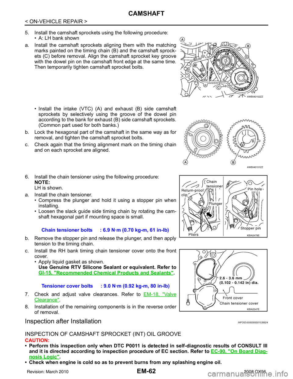
5. Install the camshaft sprockets using the following procedure:• A: LH bank shown
a. Install the camshaft sprockets aligning them with the matching marks painted on the timing chain (B) and the camshaft sprock-
ets (C) before removal. Align the camshaft sprocket key groove
with the dowel pin on the camshaft front edge at the same time.
Then temporarily tighten camshaft sprocket bolts.
• Install the intake (VTC) (A) and exhaust (B) side camshaft
sprockets by selectively using the groove of the dowel pin
according to the bank for exhaust (B) side camshaft sprockets.
(Common part used for both banks.)
b. Lock the hexagonal part of the camshaft in the same way as for removal, and tighten the camshaft sprocket bolts.
c. Check again that the timing alignment mark on the timing chain and on each sprocket are aligned.
6. Install the chain tensioner using the following procedure: NOTE:
LH is shown.
a. Install the chain tensioner. • Compress the plunger and hold it using a stopper pin when
installing.
• Loosen the slack guide side timing chain by rotating the cam- shaft hexagonal part if mounting space is small.
b. Remove the stopper pin and release the plunger, and then apply tension to the timing chain.
c. Install the RH bank timing chain tensioner cover onto the front cover.
• Apply liquid gasket as shown.Use Genuine RTV Silicone Seal ant or equivalent. Refer to
GI-15, "
Recommended Chemical Products and Sealants".
7. Check and adjust valve clearances. Refer to EM-18, "
Va l v e
Clearance".
8. Installation of the remaining components is in the reverse order of removal.
Inspection after InstallationINFOID:0000000001538824
INSPECTION OF CAMSHAFT SPROCKET (INT) OIL GROOVE
CAUTION:
• Perform this inspection only when DTC P0011 is detected in self-diagnostic results of CONSULT III
and it is directed accordi ng to inspection procedure of EC section. Refer to EC-90, "
On Board Diag-
nosis Logic".
• Check when engine is cold so as to pr event burns from any splashing engine oil.
AWBIA0152ZZ
AWBIA0151ZZ
Chain tensioner bolts : 6.9 N·m (0.70 kg-m, 61 in-lb)
Tensioner cover bolts : 9.0 N·m (0.92 kg-m, 80 in-lb)KBIA2479E
KBIA2547E
Revision: March 2010 2008 QX56
Page 1868 of 4083
OIL SEALEM-65
< ON-VEHICLE REPAIR >
C
DE
F
G H
I
J
K L
M A
EM
NP
O
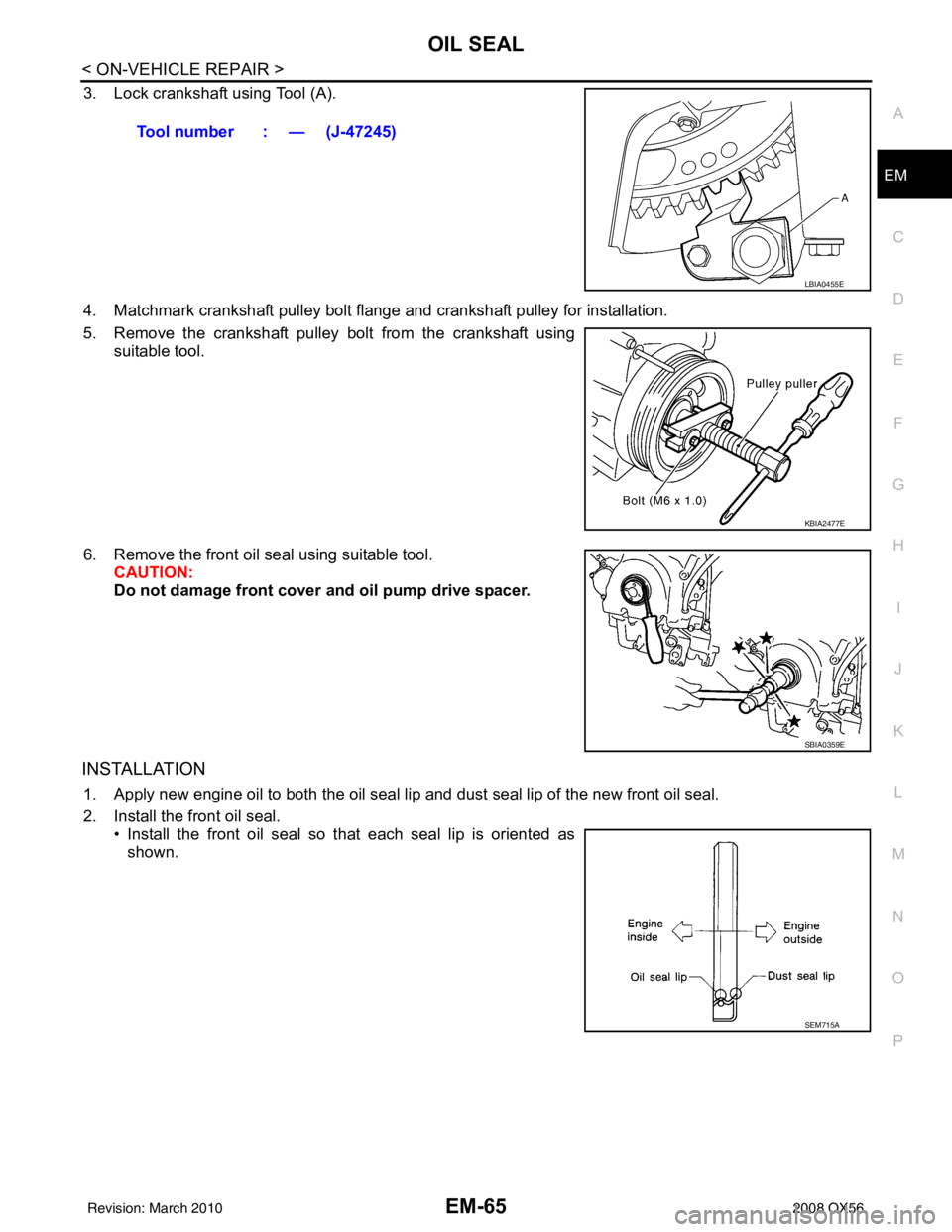
3. Lock crankshaft using Tool (A).
4. Matchmark crankshaft pulley bolt flange and crankshaft pulley for installation.
5. Remove the crankshaft pulley bolt from the crankshaft using
suitable tool.
6. Remove the front oil seal using suitable tool. CAUTION:
Do not damage front cover and oil pump drive spacer.
INSTALLATION
1. Apply new engine oil to both the oil seal lip and dust seal lip of the new front oil seal.
2. Install the front oil seal.
• Install the front oil seal so that each seal lip is oriented asshown.Tool number : — (J-47245)
LBIA0455E
KBIA2477E
SBIA0359E
SEM715A
Revision: March 2010
2008 QX56
Page 1870 of 4083
OIL SEALEM-67
< ON-VEHICLE REPAIR >
C
DE
F
G H
I
J
K L
M A
EM
NP
O
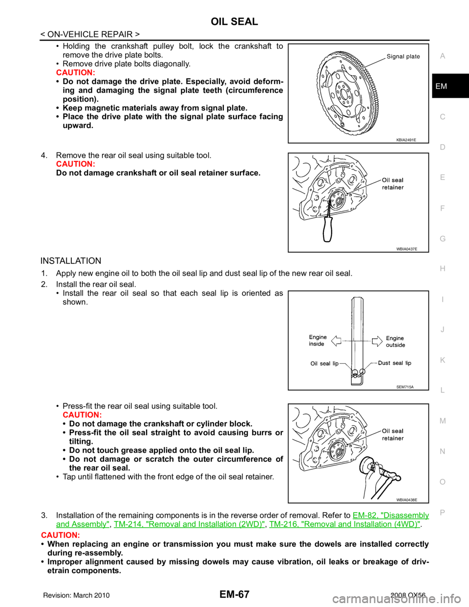
• Holding the crankshaft pulley bolt, lock the crankshaft to
remove the drive plate bolts.
• Remove drive plate bolts diagonally.
CAUTION:
• Do not damage the drive plate. Especially, avoid deform- ing and damaging the signal plate teeth (circumference
position).
• Keep magnetic materials away from signal plate.
• Place the drive plate with th e signal plate surface facing
upward.
4. Remove the rear oil seal using suitable tool. CAUTION:
Do not damage crankshaft or oil seal retainer surface.
INSTALLATION
1. Apply new engine oil to both the oil seal lip and dust seal lip of the new rear oil seal.
2. Install the rear oil seal.
• Install the rear oil seal so that each seal lip is oriented asshown.
• Press-fit the rear oil seal using suitable tool. CAUTION:
• Do not damage the crankshaft or cylinder block.
• Press-fit the oil seal straight to avoid causing burrs or
tilting.
• Do not touch grease applied onto the oil seal lip.
• Do not damage or scratch the outer circumference of
the rear oil seal.
• Tap until flattened with the front edge of the oil seal retainer.
3. Installation of the remaining components is in the reverse order of removal. Refer to EM-82, "
Disassembly
and Assembly", TM-214, "Removal and Installation (2WD)", TM-216, "Removal and Installation (4WD)".
CAUTION:
• When replacing an engine or tr ansmission you must make sure the dowels are installed correctly
during re-assembly.
• Improper alignment caused by missing dowels m ay cause vibration, oil leaks or breakage of driv-
etrain components.
KBIA2491E
WBIA0437E
SEM715A
WBIA0438E
Revision: March 2010 2008 QX56
Page 1872 of 4083
CYLINDER HEADEM-69
< ON-VEHICLE REPAIR >
C
DE
F
G H
I
J
K L
M A
EM
NP
O
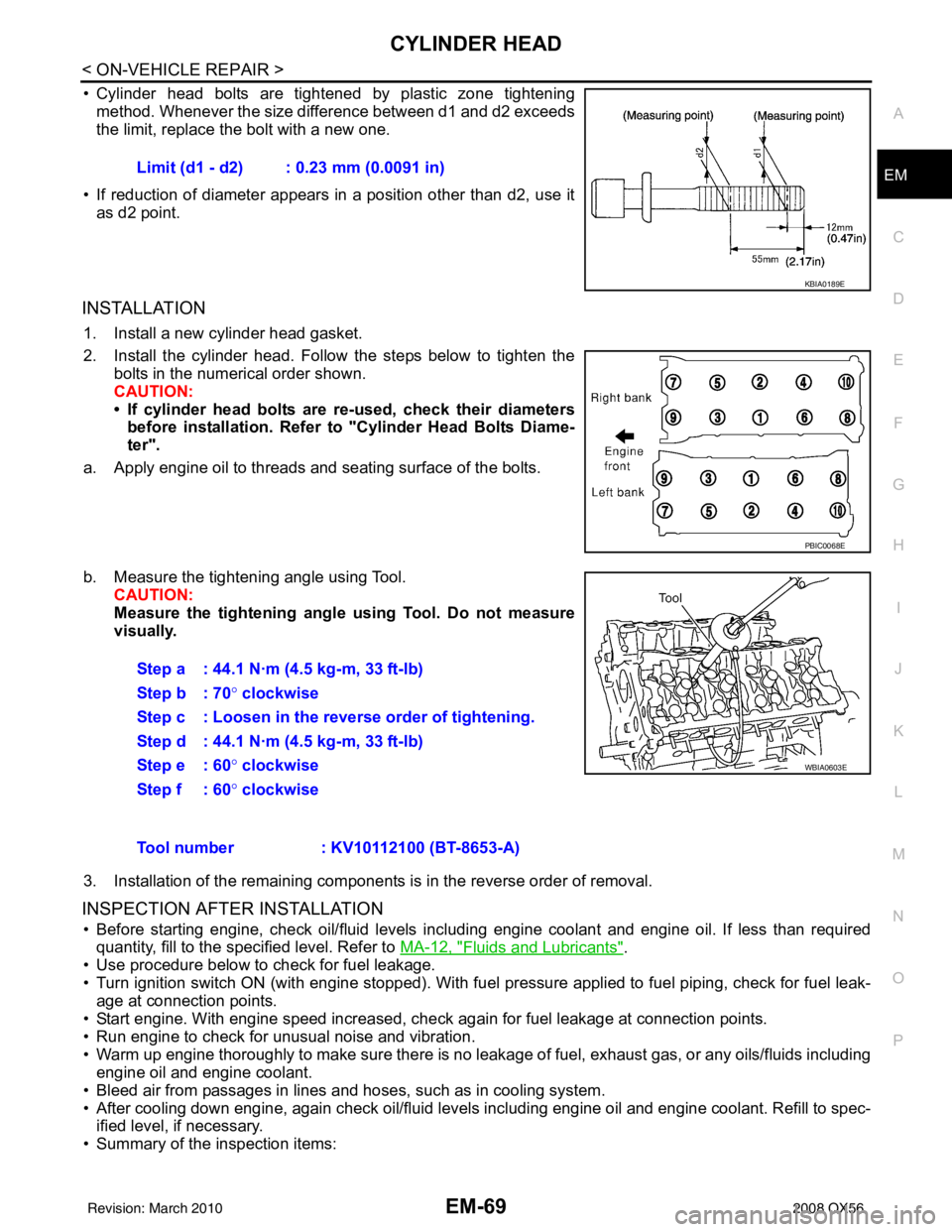
• Cylinder head bolts are tightened by plastic zone tightening
method. Whenever the size difference between d1 and d2 exceeds
the limit, replace the bolt with a new one.
• If reduction of diameter appears in a position other than d2, use it as d2 point.
INSTALLATION
1. Install a new cylinder head gasket.
2. Install the cylinder head. Follow the steps below to tighten the bolts in the numerical order shown.
CAUTION:
• If cylinder head bolts are re-used, check their diameters
before installation. Refer to "Cylinder Head Bolts Diame-
ter".
a. Apply engine oil to threads and seating surface of the bolts.
b. Measure the tightening angle using Tool. CAUTION:
Measure the tightening angl e using Tool. Do not measure
visually.
3. Installation of the remaining components is in the reverse order of removal.
INSPECTION AFTER INSTALLATION
• Before starting engine, check oil/fluid levels incl uding engine coolant and engine oil. If less than required
quantity, fill to the specified level. Refer to MA-12, "
Fluids and Lubricants".
• Use procedure below to check for fuel leakage.
• Turn ignition switch ON (with engine stopped). With fuel pressure applied to fuel piping, check for fuel leak-
age at connection points.
• Start engine. With engine speed increased, check again for fuel leakage at connection points.
• Run engine to check for unusual noise and vibration.
• Warm up engine thoroughly to make sure there is no leak age of fuel, exhaust gas, or any oils/fluids including
engine oil and engine coolant.
• Bleed air from passages in lines and hoses, such as in cooling system.
• After cooling down engine, again check oil/fluid levels including engine oil and engine coolant. Refill to spec- ified level, if necessary.
• Summary of the inspection items: Limit (d1 - d2) : 0.23 mm (0.0091 in)
KBIA0189E
PBIC0068E
Step a : 44.1 N·m (4.5 kg-m, 33 ft-lb)
Step b : 70°
clockwise
Step c : Loosen in the reverse order of tightening.
Step d : 44.1 N·m (4.5 kg-m, 33 ft-lb)
Step e : 60 ° clockwise
Step f : 60° clockwise
WBIA0603E
Tool number : KV10112100 (BT-8653-A)
Revision: March 2010 2008 QX56
Page 1883 of 4083
EM-80
< REMOVAL AND INSTALLATION >
ENGINE ASSEMBLY
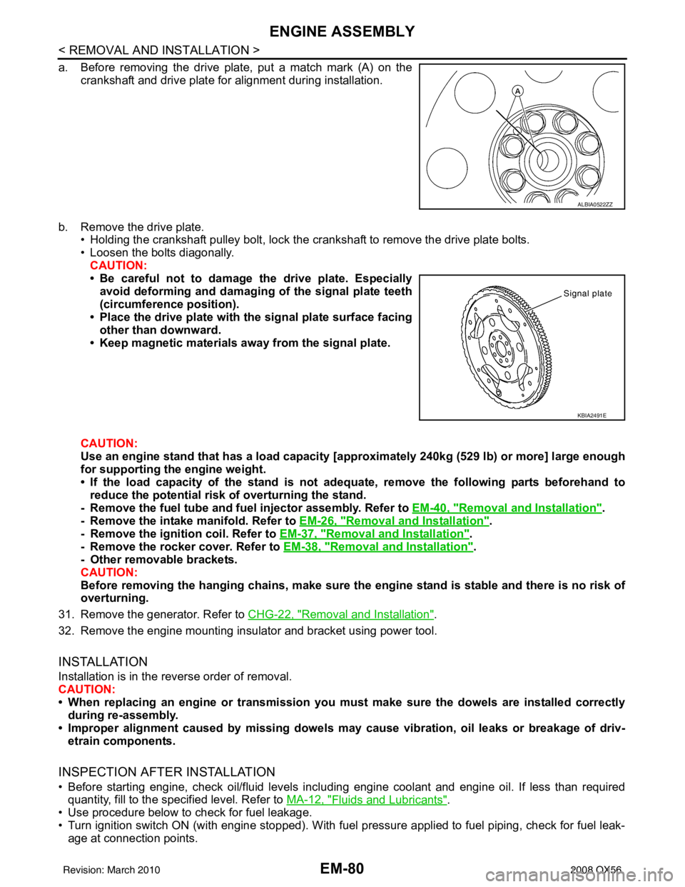
a. Before removing the drive plate, put a match mark (A) on thecrankshaft and drive plate for alignment during installation.
b. Remove the drive plate. • Holding the crankshaft pulley bolt, lock the crankshaft to remove the drive plate bolts.
• Loosen the bolts diagonally.
CAUTION:
• Be careful not to damage the drive plate. Especiallyavoid deforming and damaging of the signal plate teeth
(circumference position).
• Place the drive plate with th e signal plate surface facing
other than downward.
• Keep magnetic materials away from the signal plate.
CAUTION:
Use an engine stand that has a load capacity [a pproximately 240kg (529 lb) or more] large enough
for supporting the engine weight.
• If the load capacity of the stand is not adeq uate, remove the following parts beforehand to
reduce the potential risk of overturning the stand.
- Remove the fuel tube and fuel injector assembly. Refer to EM-40, "
Removal and Installation".
- Remove the intake manifold. Refer to EM-26, "
Removal and Installation".
- Remove the ignition coil. Refer to EM-37, "
Removal and Installation".
- Remove the rocker cover. Refer to EM-38, "
Removal and Installation".
- Other removable brackets.
CAUTION:
Before removing the hanging chains, make sure th e engine stand is stable and there is no risk of
overturning.
31. Remove the generator. Refer to CHG-22, "
Removal and Installation".
32. Remove the engine mounting insulator and bracket using power tool.
INSTALLATION
Installation is in the reverse order of removal.
CAUTION:
• When replacing an engine or transmission you mu st make sure the dowels are installed correctly
during re-assembly.
• Improper alignment caused by mi ssing dowels may cause vibration, oil leaks or breakage of driv-
etrain components.
INSPECTION AFTER INSTALLATION
• Before starting engine, check oil/fluid levels incl uding engine coolant and engine oil. If less than required
quantity, fill to the specified level. Refer to MA-12, "
Fluids and Lubricants".
• Use procedure below to check for fuel leakage.
• Turn ignition switch ON (with engine stopped). With fuel pressure applied to fuel piping, check for fuel leak- age at connection points.
ALBIA0522ZZ
KBIA2491E
Revision: March 2010 2008 QX56