Page 1821 of 4083
EM-18
< ON-VEHICLE MAINTENANCE >
CAMSHAFT VALVE CLEARANCE
CAMSHAFT VALVE CLEARANCE
Valve ClearanceINFOID:0000000001538810
INSPECTION
NOTE:
Perform the following inspection after removal, installation or replacement of camshaft or valve-related parts,
or if there are unusual engine conditions due to changes in valve clearance over time (starting, idling, and/or
noise).
1. Warm up the engine. Then stop the engine.
2. Remove the engine room cover. Refer to EM-24, "
Removal and Installation".
3. Remove the air cleaner and air duct assembly. Refer to EM-25, "
Removal and Installation".
4. Remove the RH bank and LH bank rocker covers using power tool. Refer to EM-38, "
Removal and Instal-
lation".
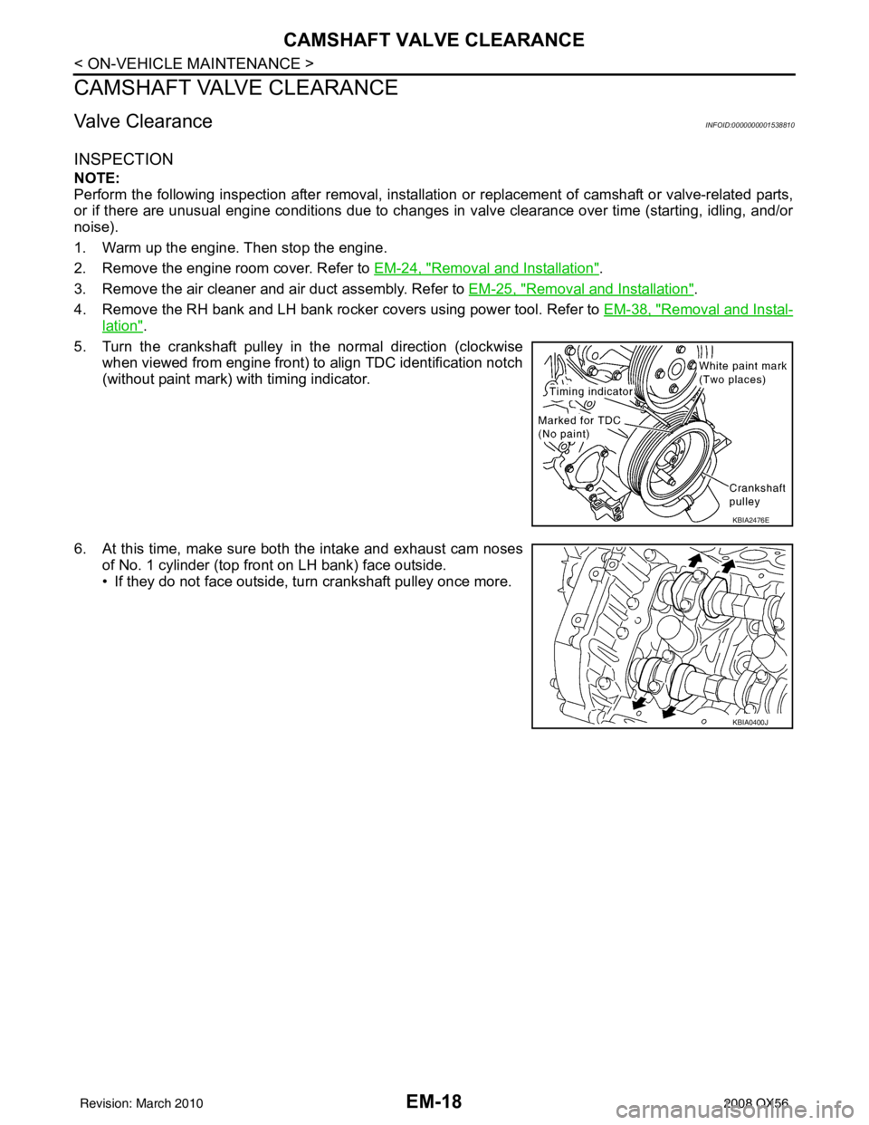
5. Turn the crankshaft pulley in the normal direction (clockwise when viewed from engine front) to align TDC identification notch
(without paint mark) with timing indicator.
6. At this time, make sure both the intake and exhaust cam noses of No. 1 cylinder (top front on LH bank) face outside.
• If they do not face outside, turn crankshaft pulley once more.
KBIA2476E
KBIA0400J
Revision: March 2010 2008 QX56
Page 1822 of 4083
CAMSHAFT VALVE CLEARANCEEM-19
< ON-VEHICLE MAINTENANCE >
C
DE
F
G H
I
J
K L
M A
EM
NP
O
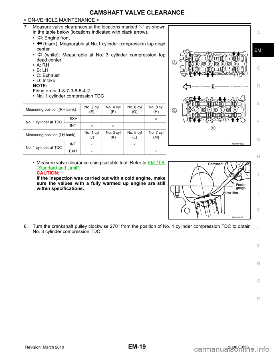
7. Measure valve clearances at the locations marked “×
” as shown
in the table below (locations indicated with black arrow).
• : Engine front
• (black): Measurable at No.1 cylinder compression top dead center
• (white): Measurable at No. 3 cylinder compression top dead center
•A: RH
•B: LH
• C: Exhaust
• D: Intake
NOTE:
Firing order 1-8-7-3-6-5-4-2
• No. 1 cylinder compression TDC
• Measure valve clearance using suitable tool. Refer to EM-108,
"Standard and Limit".
CAUTION:
If the inspection was carried out with a cold engine, make
sure the values with a fully warmed up engine are still
within specifications.
8. Turn the crankshaft pulley clockwise 270 ° from the position of No. 1 cylinder compression TDC to obtain
No. 3 cylinder compression TDC.
Measuring position (RH bank) No. 2 cyl
(E) No. 4 cyl
(F) No. 6 cyl
(G) No. 8 cyl
(H)
No. 1 cylinder at TDC EXH
×
INT ××
Measuring position (LH bank) No. 1 cyl
(J) No. 3 cyl
(K) No. 5 cyl
(L) No. 7 cyl
(M)
No. 1 cylinder at TDC INT
××
EXH ××
WBIA0713E
KBIA0185E
Revision: March 2010 2008 QX56
Page 1824 of 4083
CAMSHAFT VALVE CLEARANCEEM-21
< ON-VEHICLE MAINTENANCE >
C
DE
F
G H
I
J
K L
M A
EM
NP
O
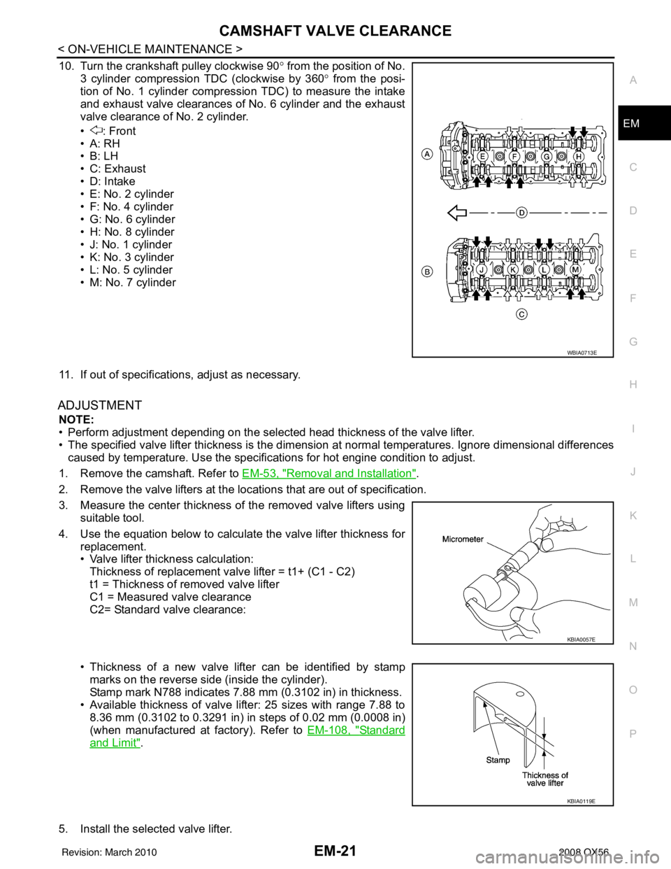
10. Turn the crankshaft pulley clockwise 90°
from the position of No.
3 cylinder compression TDC (clockwise by 360 ° from the posi-
tion of No. 1 cylinder compression TDC) to measure the intake
and exhaust valve clearances of No. 6 cylinder and the exhaust
valve clearance of No. 2 cylinder.
• : Front
•A: RH
•B: LH
• C: Exhaust
• D: Intake
• E: No. 2 cylinder
• F: No. 4 cylinder
• G: No. 6 cylinder
• H: No. 8 cylinder
• J: No. 1 cylinder
• K: No. 3 cylinder
• L: No. 5 cylinder
• M: No. 7 cylinder
11. If out of specifications, adjust as necessary.
ADJUSTMENT
NOTE:
• Perform adjustment depending on the selected head thickness of the valve lifter.
• The specified valve lifter thickness is the dimension at normal temperatures. Ignore dimensional differences
caused by temperature. Us e the specifications for hot engine condition to adjust.
1. Remove the camshaft. Refer to EM-53, "
Removal and Installation".
2. Remove the valve lifters at the locations that are out of specification.
3. Measure the center thickness of the removed valve lifters using suitable tool.
4. Use the equation below to calculate the valve lifter thickness for replacement.
• Valve lifter thickness calculation:Thickness of replacement valve lifter = t1+ (C1 - C2)
t1 = Thickness of removed valve lifter
C1 = Measured valve clearance
C2= Standard valve clearance:
• Thickness of a new valve lifter can be identified by stamp marks on the reverse side (inside the cylinder).
Stamp mark N788 indicates 7.88 mm (0.3102 in) in thickness.
• Available thickness of valve lifter: 25 sizes with range 7.88 to 8.36 mm (0.3102 to 0.3291 in) in steps of 0.02 mm (0.0008 in)
(when manufactured at factory). Refer to EM-108, "
Standard
and Limit".
5. Install the selected valve lifter.
WBIA0713E
KBIA0057E
KBIA0119E
Revision: March 2010 2008 QX56
Page 1837 of 4083
EM-34
< ON-VEHICLE REPAIR >
OIL PAN AND OIL STRAINER
b. Insert Tool between the lower oil pan and the upper oil pan.CAUTION:
• Be careful not to damage the mating surface.
• Do not insert a screwdriver, this will damage the matingsurfaces.
c. Slide (1) the Tool by tapping (2) its side with a hammer to remove the lower oil pan from the upper oil pan.
3. Remove the oil strainer from the oil pan (upper).
4. Remove the oil pan (upper) using the following steps.
a. Remove the oil pan (upper) bolts a shown.
b. Remove the oil pan (upper) from the cylinder block by prying it at the points shown, using suitable tool.
CAUTION:
Do not damage mating surface.
5. Remove the O-rings from the oil pump and front cover. NOTE:
Do not reuse O-rings.
INSPECTION AFTER REMOVAL
Clean the oil strainer.
INSTALLATION
Tool number : KV10111100 (J-37228)
WBIA0566E
KBIA2467E
KBIA2468E
KBIA2469E
Revision: March 2010 2008 QX56
Page 1849 of 4083
EM-46
< ON-VEHICLE REPAIR >
TIMING CHAIN
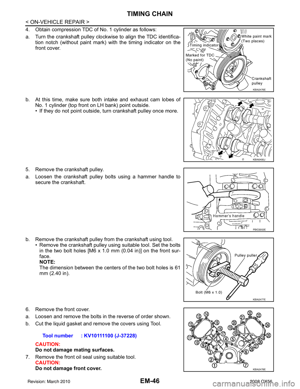
4. Obtain compression TDC of No. 1 cylinder as follows:
a. Turn the crankshaft pulley clockwise to align the TDC identifica-tion notch (without paint mark) with the timing indicator on the
front cover.
b. At this time, make sure both intake and exhaust cam lobes of No. 1 cylinder (top front on LH bank) point outside.
• If they do not point outside, turn crankshaft pulley once more.
5. Remove the crankshaft pulley.
a. Loosen the crankshaft pulley bolts using a hammer handle to secure the crankshaft.
b. Remove the crankshaft pulley from the crankshaft using tool. • Remove the crankshaft pulley using suitable tool. Set the boltsin the two bolt holes [M6 x 1.0 mm (0.04 in)] on the front sur-
face.
NOTE:
The dimension between the centers of the two bolt holes is 61
mm (2.40 in).
6. Remove the front cover.
a. Loosen and remove the bolts in the reverse of order shown.
b. Cut the liquid gasket and remove the covers using Tool. CAUTION:
Do not damage mating surfaces.
7. Remove the front oil seal using suitable tool. CAUTION:
Do not damage front cover.
KBIA2476E
KBIA0400J
PBIC0053E
KBIA2477E
Tool number : KV10111100 (J-37228)
KBIA2478E
Revision: March 2010 2008 QX56
Page 1852 of 4083
TIMING CHAINEM-49
< ON-VEHICLE REPAIR >
C
DE
F
G H
I
J
K L
M A
EM
NP
O
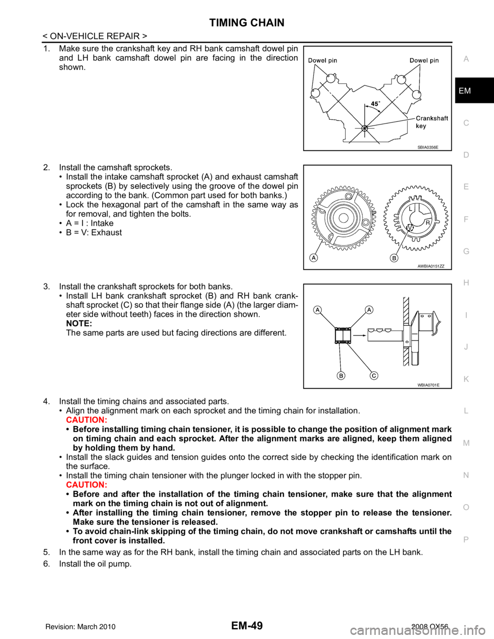
1. Make sure the crankshaft key and RH bank camshaft dowel pin
and LH bank camshaft dowel pin are facing in the direction
shown.
2. Install the camshaft sprockets. • Install the intake camshaft sprocket (A) and exhaust camshaftsprockets (B) by selectively us ing the groove of the dowel pin
according to the bank. (Common part used for both banks.)
• Lock the hexagonal part of the camshaft in the same way as for removal, and tighten the bolts.
• A = I : Intake
• B = V: Exhaust
3. Install the crankshaft sprockets for both banks. • Install LH bank crankshaft sprocket (B) and RH bank crank-shaft sprocket (C) so that their flange side (A) (the larger diam-
eter side without teeth) faces in the direction shown.
NOTE:
The same parts are used but facing directions are different.
4. Install the timing chains and associated parts. • Align the alignment mark on each sprocket and the timing chain for installation.
CAUTION:
• Before installing timing chain tensioner, it is possible to change the position of alignment mark
on timing chain and each sprocket . After the alignment marks are aligned, keep them aligned
by holding them by hand.
• Install the slack guides and tension guides onto the correct side by checking the identification mark on
the surface.
• Install the timing chain tensioner with the plunger locked in with the stopper pin.
CAUTION:
• Before and after the installation of the timing chain tensioner, make sure that the alignment
mark on the timing chain is not out of alignment.
• After installing the timing chain tensioner, remove the stopp er pin to release the tensioner.
Make sure the tensioner is released.
• To avoid chain-link skipping of the timing chain, do not move crankshaft or camshafts until the
front cover is installed.
5. In the same way as for the RH bank, install the timing chain and associated parts on the LH bank.
6. Install the oil pump.
SBIA0356E
AWBIA0151ZZ
WBIA0701E
Revision: March 2010 2008 QX56
Page 1853 of 4083
EM-50
< ON-VEHICLE REPAIR >
TIMING CHAIN
7. Install the oil pump drive spacer as follows:• Install so that the front mark on the front edge of the oil pumpdrive spacer faces the front of the engine.
• Insert the oil pump drive spacer according to the directions of the crankshaft key and the two flat surfaces of the oil pump
inner rotor.
• If the positional relationship does not allow the insertion, rotate the oil pump inner rotor to allow the oil pump drive spacer to
be inserted.
8. Install the front oil seal using suitable tool. CAUTION:
Do not scratch or make burrs on the circumference of the
oil seal.
9. Install the chain tensioner cover. • Apply liquid gasket as shown.
Use Genuine RTV Silicone Seal ant or equivalent. Refer to
GI-15, "
Recommended Chemical Products and Sealants".
10. Install the front cover as follows:
a. Install a new O-ring on the cylinder block.
KBIA2490E
PBIC0059E
KBIA2547E
KBIA2516E
Revision: March 2010 2008 QX56
Page 1854 of 4083
TIMING CHAINEM-51
< ON-VEHICLE REPAIR >
C
DE
F
G H
I
J
K L
M A
EM
NP
O
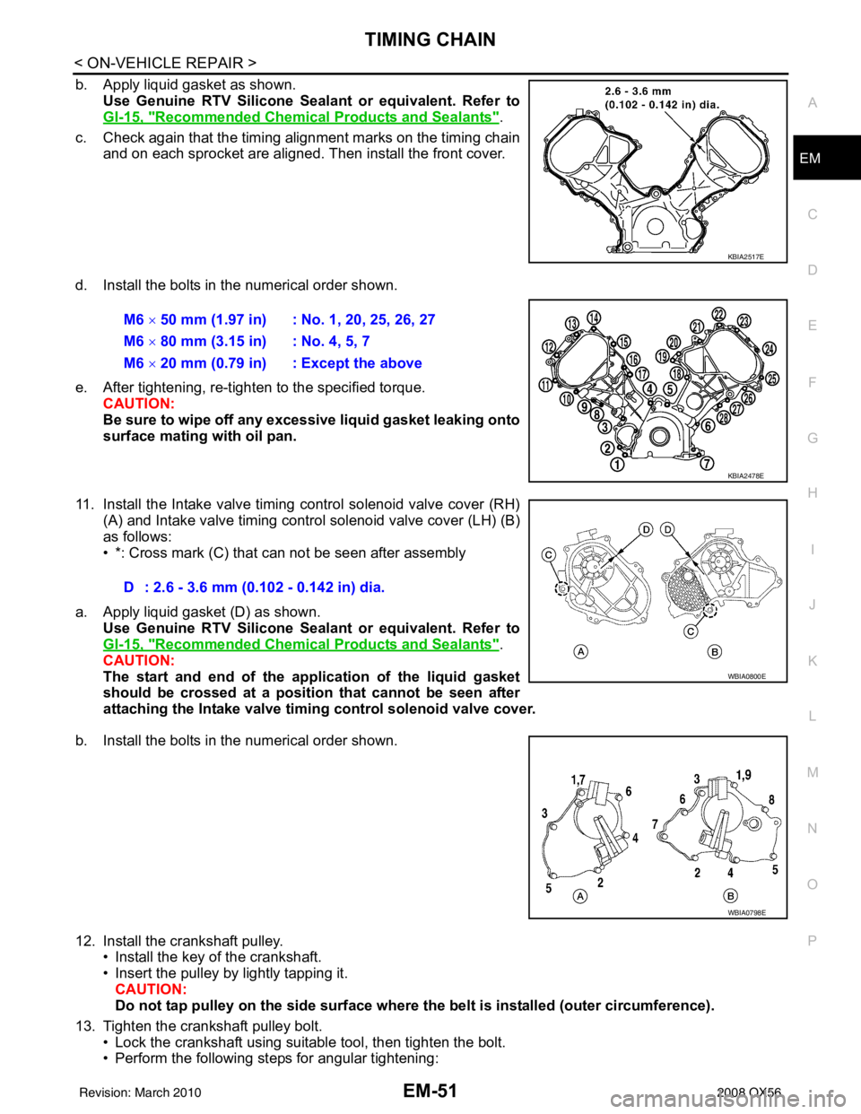
b. Apply liquid gasket as shown.
Use Genuine RTV Silicone Seal ant or equivalent. Refer to
GI-15, "
Recommended Chemical Products and Sealants".
c. Check again that the timing alignment marks on the timing chain and on each sprocket are aligned. Then install the front cover.
d. Install the bolts in the numerical order shown.
e. After tightening, re-tighten to the specified torque. CAUTION:
Be sure to wipe off any excessive liquid gasket leaking onto
surface mating with oil pan.
11. Install the Intake valve timing control solenoid valve cover (RH) (A) and Intake valve timing control solenoid valve cover (LH) (B)
as follows:
• *: Cross mark (C) that can not be seen after assembly
a. Apply liquid gasket (D) as shown. Use Genuine RTV Silicone Seal ant or equivalent. Refer to
GI-15, "
Recommended Chemical Products and Sealants".
CAUTION:
The start and end of the appl ication of the liquid gasket
should be crossed at a positi on that cannot be seen after
attaching the Intake valve timing control solenoid valve cover.
b. Install the bolts in the numerical order shown.
12. Install the crankshaft pulley. • Install the key of the crankshaft.
• Insert the pulley by lightly tapping it.
CAUTION:
Do not tap pulley on the side surface where th e belt is installed (outer circumference).
13. Tighten the crankshaft pulley bolt. • Lock the crankshaft using suitable tool, then tighten the bolt.
• Perform the following steps for angular tightening:
KBIA2517E
M6 × 50 mm (1.97 in) : No. 1, 20, 25, 26, 27
M6 × 80 mm (3.15 in) : No. 4, 5, 7
M6 × 20 mm (0.79 in) : Except the above
KBIA2478E
D : 2.6 - 3.6 mm (0.102 - 0.142 in) dia.
WBIA0800E
WBIA0798E
Revision: March 2010 2008 QX56