Page 2996 of 4083

RF-12
< COMPONENT DIAGNOSIS >
SUNROOF SWITCH CIRCUIT
SUNROOF SWITCH CIRCUIT
DescriptionINFOID:0000000001731930
The BCM supplies power to the integrated CPU of the sunroof motor assembly. The tilt and slide functions of
the sunroof motor assembly is controlled by the sunroof switch.
Component Function CheckINFOID:0000000001731931
1. CHECK SUNROOF MOTOR FUNCTION
Do tilt up/down & slide open/close functi ons operate normally with sunroof switch?
Is the inspection result normal?
YES >> Sunroof motor assembly is OK.
NO >> Refer to RF-10, "
SUNROOF MOTOR ASSEMBLY : DiagnosisProcedure".
Diagnosis ProcedureINFOID:0000000001731932
1. CHECK SUNROOF SWITCH INPUT SIGNAL
1. Turn ignition switch ON.
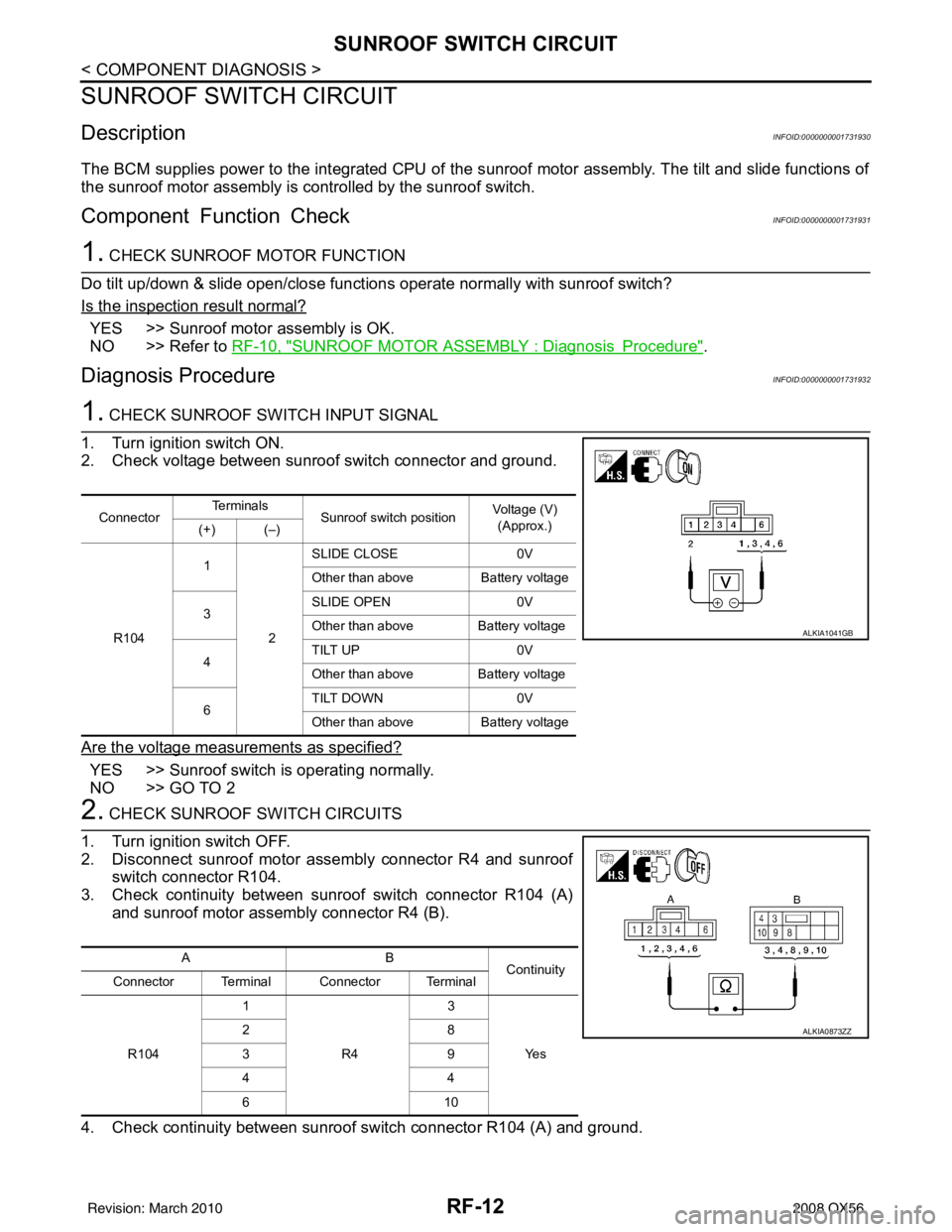
2. Check voltage between sunroof switch connector and ground.
Are the voltage measurements as specified?
YES >> Sunroof switch is operating normally.
NO >> GO TO 2
2. CHECK SUNROOF SWITCH CIRCUITS
1. Turn ignition switch OFF.
2. Disconnect sunroof motor assembly connector R4 and sunroof switch connector R104.
3. Check continuity between sunroof switch connector R104 (A) and sunroof motor assembly connector R4 (B).
4. Check continuity between sunroof switch connector R104 (A) and ground.
Connector Te r m i n a l s
Sunroof switch position Voltage (V)
(Approx.)
(+) (–)
R104 1
2SLIDE CLOSE
0V
Other than above Battery voltage
3 SLIDE OPEN
0V
Other than above Battery voltage
4 TILT UP
0V
Other than above Battery voltage
6 TILT DOWN
0V
Other than above Battery voltage
ALKIA1041GB
AB
Continuity
Connector Terminal Connector Terminal
R104 1
R4 3
Ye s
28
39
44
61
0
ALKIA0873ZZ
Revision: March 2010 2008 QX56
Page 2997 of 4083
SUNROOF SWITCH CIRCUITRF-13
< COMPONENT DIAGNOSIS >
C
DE
F
G H
I
J
L
M A
B
RF
N
O P
Are the continuity test results as specified?
YES >> GO TO 3
NO >> Repair harness or connector.
3. CHECK SUNROOF SWITCH
1. Check continuity between sunroof switch terminals.
Are the continuity test results as specified?
YES >> Sunroof switch is operating normally.
NO >> Replace sunroof switch (map lamp assembly).
A —Continuity
Connector Terminal
R104 1
Ground No
2
3
4
6
Terminals
Sunroof switch position Continuity
1
2SLIDE CLOSE
Yes
Other than above No
3 SLIDE OPEN
Yes
Other than above No
4 TILT UP
Yes
Other than above No
6 TILT DOWN
Yes
Other than above No
ALKIA0874ZZ
Revision: March 2010 2008 QX56
Page 3014 of 4083

RF-30
< ECU DIAGNOSIS >
SUNROOF SYSTEM
SUNROOF SYSTEM
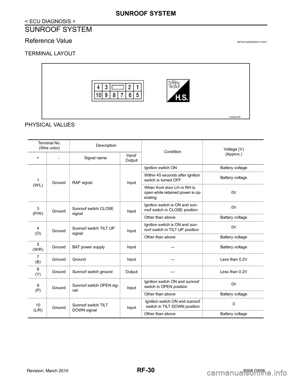
Reference ValueINFOID:0000000001731937
TERMINAL LAYOUT
PHYSICAL VALUES
LIIA2447E
Te r m i n a l N o .(Wire color) Description
ConditionVoltage (V)
(Approx.)
+ - Signal nameInput/
Output
1
(W/L) Ground RAP signal
InputIgnition switch ON
Battery voltage
Within 45 seconds after ignition
switch is turned OFF Battery voltage
When front door LH or RH is
open while retained power is op-
erating 0V
3
(P/W) Ground Sunroof switch CLOSE
signal InputIgnition switch is ON and sun-
roof switch in CLOSE position
0V
Other than above Battery voltage
4
(O) Ground Sunroof switch TILT UP
signal
InputIgnition switch is ON and sun-
roof switch in TILT UP position
0V
Other than above Battery voltage
5
(W/R) Ground BAT power supply
Input— Battery voltage
7
(B) Ground Ground
Input— Less than 0.2V
8
(Y) Ground Sunroof switch ground Output
—Less than 0.2V
9
(P) Ground
Sunroof switch OPEN sig-
nal InputIgnition switch ON and sunroof
switch in OPEN position
0V
Other than above Battery voltage
10
(L/R) Ground Sunroof switch TILT
DOWN signal InputIgnition switch ON and sunroof
switch in TILT DOWN position 0
Other than above Battery voltage
Revision: March 2010 2008 QX56
Page 3015 of 4083
SUNROOF SYSTEMRF-31
< ECU DIAGNOSIS >
C
DE
F
G H
I
J
L
M A
B
RF
N
O P
Wiring DiagramINFOID:0000000001731938
AAKWA0138GB
Revision: March 2010 2008 QX56
Page 3016 of 4083
RF-32
< ECU DIAGNOSIS >
SUNROOF SYSTEM
ALKIA0863GB
Revision: March 20102008 QX56
Page 3017 of 4083
SUNROOF SYSTEMRF-33
< ECU DIAGNOSIS >
C
DE
F
G H
I
J
L
M A
B
RF
N
O P
ALKIA0864GB
Revision: March 2010 2008 QX56
Page 3018 of 4083
RF-34
< ECU DIAGNOSIS >
SUNROOF SYSTEM
AWKIA0104GB
Revision: March 20102008 QX56
Page 3019 of 4083
SUNROOF DOES NOT OPERATE PROPERLYRF-35
< SYMPTOM DIAGNOSIS >
C
DE
F
G H
I
J
L
M A
B
RF
N
O P
SYMPTOM DIAGNOSIS
SUNROOF DOES NOT OPERATE PROPERLY
Diagnosis ProcedureINFOID:0000000001731939
1. CHECK BCM POWER SUPPLY AND GROUND CIRCUIT
Check BCM power supply and ground circuit.
Refer to BCS-32, "
Diagnosis Procedure".
>> GO TO 2
2. CHECK SUNROOF MOTOR ASSEMBLY POWER SUPPLY AND GROUND CIRCUIT
Check sunroof motor assembly power supply and ground circuit.
Refer to RF-12, "
ComponentFunctionCheck".
>> GO TO 3
3. CHECK SUNROOF SWITCH CIRCUIT
Check sunroof switch circuit.
Refer to RF-12, "
Diagnosis Procedure".
Is the inspection result normal?
>> Check intermittent incident. Refer to GI-38, "Intermittent Incident".
Revision: March 2010 2008 QX56