2008 INFINITI QX56 warning
[x] Cancel search: warningPage 1605 of 4083
![INFINITI QX56 2008 Factory Service Manual EC-306
< COMPONENT DIAGNOSIS >[VK56DE]
P1217 ENGINE OVER TEMPERATURE
P1217 ENGINE OVER TEMPERATURE
On Board Diagn
osis LogicINFOID:0000000001351714
NOTE:
•If DTC P1217 is displayed with DTC U1000 or INFINITI QX56 2008 Factory Service Manual EC-306
< COMPONENT DIAGNOSIS >[VK56DE]
P1217 ENGINE OVER TEMPERATURE
P1217 ENGINE OVER TEMPERATURE
On Board Diagn
osis LogicINFOID:0000000001351714
NOTE:
•If DTC P1217 is displayed with DTC U1000 or](/manual-img/42/57030/w960_57030-1604.png)
EC-306
< COMPONENT DIAGNOSIS >[VK56DE]
P1217 ENGINE OVER TEMPERATURE
P1217 ENGINE OVER TEMPERATURE
On Board Diagn
osis LogicINFOID:0000000001351714
NOTE:
•If DTC P1217 is displayed with DTC U1000 or U1001, first perform the trouble diagnosis for DTC
U1000, U1001. Refer to EC-87
.
• If DTC P1217 is displayed with DTC U1010, first pe rform the trouble diagnosis for DTC U1010. Refer
to EC-88
.
If the cooling fan or another component in the cooling system malfunctions, engine coolant temperature will
rise.
When the engine coolant temperature reaches an abnorma lly high temperature condition, a malfunction is
indicated.
This self-diagnosis has the one trip detection logic.
CAUTION:
When a malfunction is indicated, be sure to replace the coolant. Refer to CO-11, "
Changing Engine
Coolant". Also, replace the engine oil. Refer to LU-9, "Changing Engine Oil".
1. Fill radiator with coolant up to specified level with a filling speed of 2 liters per minute. Be sure to
use coolant with the proper mixture ratio. Refer to CO-10
.
2. After refilling coolant, run engine to en sure that no water-flow noise is emitted.
Overall Function CheckINFOID:0000000001351715
Use this procedure to check the overall function of the cooling fan. During this check, a DTC might not be con-
firmed.
WARNING:
Never remove the radiator cap and/or reservoir tank cap when the engine is hot. Serious burns could
be caused by high pressure fluid escaping fr om the radiator and/or reservoir tank.
Wrap a thick cloth around cap. Carefully remove the cap by turning it a quarter turn to allow built-up
pressure to escape. Then turn the cap all the way off.
WITH CONSULT-III
1. Check the coolant level in the reservoir tank and radiator. Allow engine to cool before checking coolant level.
If the coolant level in the reservoir tank and/or radiator is below
the proper range, skip the following steps and go to EC-395,
"Diagnosis Procedure".
2. Confirm whether customer filled the coolant or not. If customer
filled the coolant, skip the following steps and go to EC-395,
"Diagnosis Procedure".
3. Turn ignition switch ON.
DTC No. Trouble diagnosis name DTC detecting condition Possible cause
P1217
1217 Engine over tempera-
ture (Overheat) • Cooling fan does not operate properly (Over-
heat).
• Cooling fan system does not operate proper-
ly (Overheat).
• Engine coolant was not added to the system using the proper filling method.
• Engine coolant is not within the specified range. • Harness or connectors
(The cooling fan circuit is open or short-
ed.)
• Cooling fan
• Cooling fan (crankshaft diven)
• IPDM E/R (Cooling fan relay)
•Radiator hose
•Radiator
•Radiator cap
• Reservoir tank
• Reservoir tank cap
• Water pump
•Thermostat
For more informat ion, refer to EC-308,
"Main 13 Causes of Overheating".
SEF621W
Revision: March 2010 2008 QX56
Page 1715 of 4083
![INFINITI QX56 2008 Factory Service Manual EC-416
< COMPONENT DIAGNOSIS >[VK56DE]
ON BOARD REFUELING VAPOR RECOVERY (ORVR)
ON BOARD REFUELING VAPOR RECOVERY (ORVR)
System DescriptionINFOID:0000000001351317
From the beginning of refueling, the INFINITI QX56 2008 Factory Service Manual EC-416
< COMPONENT DIAGNOSIS >[VK56DE]
ON BOARD REFUELING VAPOR RECOVERY (ORVR)
ON BOARD REFUELING VAPOR RECOVERY (ORVR)
System DescriptionINFOID:0000000001351317
From the beginning of refueling, the](/manual-img/42/57030/w960_57030-1714.png)
EC-416
< COMPONENT DIAGNOSIS >[VK56DE]
ON BOARD REFUELING VAPOR RECOVERY (ORVR)
ON BOARD REFUELING VAPOR RECOVERY (ORVR)
System DescriptionINFOID:0000000001351317
From the beginning of refueling, the air and vapor insi
de the fuel tank go through refueling EVAP vapor cut
valve and EVAP/ORVR line to the EVAP canister. The vapor is absorbed by the EVAP canister and the air is
released to the atmosphere.
When the refueling has reached the full level of the fuel tank, the refueling EVAP vapor cut valve is closed and
refueling is stopped because of auto shut-off. The vapor which was absorbed by the EVAP canister is purged
during driving.
WARNING:
When conducting inspections below, be sure to observe the following:
• Put a “CAUTION: FLAMMABLE” sign in workshop.
• Do not smoke while servicing fuel system. Keep open flames and sparks away from work area.
• Be sure to furnish the workshop with a CO
2 fire extinguisher.
CAUTION:
• Before removing fuel line parts, carry out the following procedures:
- Put drained fuel in an explosion-pr oof container and put lid on securely.
- Release fuel pressure from fuel line. Refer to EC-494, "
Fuel Pressure Check" .
- Disconnect battery ground cable.
• Always replace O-ring when the fu el gauge retainer is removed.
• Do not kink or twist hose and tube when they are installed.
• Do not tighten hose and clamps excessively to avoid damaging hoses.
• After installation, run engine and check for fuel leaks at connection.
• Do not attempt to top off the fuel tank afte r the fuel pump nozzle shuts off automatically.
Continued refueling may cause fuel overflow, r esulting in fuel spray and possibly a fire.
Diagnosis ProcedureINFOID:0000000001351318
SYMPTOM: FUEL ODOR FROM EVAP CANISTER IS STRONG.
1.CHECK EVAP CANISTER
1. Remove EVAP canister with EVAP canister vent control valve and EVAP control system pressure sensor attached.
2. Weigh the EVAP canister with EVAP canister vent control valve and EVAP control system pressure sensor
attached.
The weight should be l ess than 2.5 kg (5.5 lb).
OK or NG
OK >> GO TO 2.
NG >> GO TO 3.
2.CHECK IF EVAP CANISTER SATURATED WITH WATER
PBIB1068E
Revision: March 2010 2008 QX56
Page 1785 of 4083
![INFINITI QX56 2008 Factory Service Manual EC-486
< PRECAUTION >[VK56DE]
PRECAUTIONS
PRECAUTION
PRECAUTIONS
Precaution for Supplemental Restraint Syst
em (SRS) "AIR BAG" and "SEAT BELT
PRE-TENSIONER"
INFOID:0000000006054103
The Supplemental R INFINITI QX56 2008 Factory Service Manual EC-486
< PRECAUTION >[VK56DE]
PRECAUTIONS
PRECAUTION
PRECAUTIONS
Precaution for Supplemental Restraint Syst
em (SRS) "AIR BAG" and "SEAT BELT
PRE-TENSIONER"
INFOID:0000000006054103
The Supplemental R](/manual-img/42/57030/w960_57030-1784.png)
EC-486
< PRECAUTION >[VK56DE]
PRECAUTIONS
PRECAUTION
PRECAUTIONS
Precaution for Supplemental Restraint Syst
em (SRS) "AIR BAG" and "SEAT BELT
PRE-TENSIONER"
INFOID:0000000006054103
The Supplemental Restraint System such as “A IR BAG” and “SEAT BELT PRE-TENSIONER”, used along
with a front seat belt, helps to reduce the risk or severity of injury to the driver and front passenger for certain
types of collision. This system includes seat belt switch inputs and dual stage front air bag modules. The SRS
system uses the seat belt switches to determine the front air bag deployment, and may only deploy one front
air bag, depending on the severity of a collision and w hether the front occupants are belted or unbelted.
Information necessary to service the system safely is included in the SR and SB section of this Service Man-
ual.
WARNING:
• To avoid rendering the SRS inopera tive, which could increase the risk of personal injury or death in
the event of a collision which would result in air bag inflation, all maintenance must be performed by
an authorized NISSAN/INFINITI dealer.
• Improper maintenance, including in correct removal and installation of the SRS, can lead to personal
injury caused by unintent ional activation of the system. For re moval of Spiral Cable and Air Bag
Module, see the SR section.
• Do not use electrical test equipmen t on any circuit related to the SRS unless instructed to in this
Service Manual. SRS wiring harn esses can be identified by yellow and/or orange harnesses or har-
ness connectors.
PRECAUTIONS WHEN USING POWER TOOLS (AIR OR ELECTRIC) AND HAMMERS
WARNING:
• When working near the Airbag Diagnosis Sensor Unit or other Airbag System sensors with the Igni-
tion ON or engine running, DO NOT use air or electri c power tools or strike near the sensor(s) with a
hammer. Heavy vibration could activate the sensor( s) and deploy the air bag(s), possibly causing
serious injury.
• When using air or electric power tools or hammers , always switch the Ignition OFF, disconnect the
battery, and wait at least 3 minu tes before performing any service.
Precaution Necessary for Steering W heel Rotation After Battery Disconnect
INFOID:0000000006211820
NOTE:
• This Procedure is applied only to models with Intelligent Key system and NATS (NISSAN ANTI-THEFT SYS-
TEM).
• Remove and install all control units after disconnecting both battery cables with the ignition knob in the
″LOCK ″ position.
• Always use CONSULT-III to perform self-diagnosis as a part of each function inspection after finishing work.
If DTC is detected, perform trouble diagnosis according to self-diagnostic results.
For models equipped with the Intelligent Key system and NATS, an electrically controlled steering lock mech-
anism is adopted on the key cylinder.
For this reason, if the battery is disconnected or if the battery is discharged, the steering wheel will lock and
steering wheel rotation will become impossible.
If steering wheel rotation is required when battery pow er is interrupted, follow the procedure below before
starting the repair operation.
OPERATION PROCEDURE
1. Connect both battery cables. NOTE:
Supply power using jumper cables if battery is discharged.
2. Use the Intelligent Key or mechanical key to turn the ignition switch to the ″ACC ″ position. At this time, the
steering lock will be released.
3. Disconnect both battery cables. The steering lock will remain released and the steering wheel can be rotated.
4. Perform the necessary repair operation.
Revision: March 2010 2008 QX56
Page 1806 of 4083
PRECAUTIONSEM-3
< PRECAUTION >
C
DE
F
G H
I
J
K L
M A
EM
NP
O
PRECAUTION
PRECAUTIONS
Precaution for Supplemental
Restraint System (SRS) "AIR BAG" and "SEAT BELT
PRE-TENSIONER"
INFOID:0000000004857552
The Supplemental Restraint System such as “AIR BAG” and “SEAT BELT PRE-TENSIONER”, used along
with a front seat belt, helps to reduce the risk or severi ty of injury to the driver and front passenger for certain
types of collision. This system includes seat belt switch inputs and dual stage front air bag modules. The SRS
system uses the seat belt switches to determine the front air bag deployment, and may only deploy one front
air bag, depending on the severity of a collision and w hether the front occupants are belted or unbelted.
Information necessary to service the system safely is included in the SR and SB section of this Service Man-
ual.
WARNING:
• To avoid rendering the SRS inoper ative, which could increase the risk of personal injury or death in
the event of a collision which would result in air bag inflation, all maintenance must be performed by
an authorized NISSAN/INFINITI dealer.
• Improper maintenance, including in correct removal and installation of the SRS, can lead to personal
injury caused by unintentional act ivation of the system. For removal of Spiral Cable and Air Bag
Module, see the SR section.
• Do not use electrical test equipm ent on any circuit related to the SRS unless instructed to in this
Service Manual. SRS wiring harnesses can be identi fied by yellow and/or orange harnesses or har-
ness connectors.
PRECAUTIONS WHEN USING POWER TOOLS (AIR OR ELECTRIC) AND HAMMERS
WARNING:
• When working near the Airbag Diagnosis Sensor Un it or other Airbag System sensors with the Igni-
tion ON or engine running, DO NOT use air or el ectric power tools or strike near the sensor(s) with a
hammer. Heavy vibration could activate the sensor( s) and deploy the air bag(s), possibly causing
serious injury.
• When using air or electric power tools or hammers, always switch the Ignition OFF, disconnect the battery, and wait at least 3 minutes before performing any service.
Precaution Necessary for Steering Wheel Rotation After Battery Disconnect
INFOID:0000000004857588
NOTE:
• This Procedure is applied only to models with Intelligent Key system and NATS (NISSAN ANTI-THEFT SYS-
TEM).
• Remove and install all control units after disconnecti ng both battery cables with the ignition knob in the
″ LOCK ″ position.
• Always use CONSULT-III to perform self-diagnosis as a part of each function inspection after finishing work.
If DTC is detected, perform trouble diagnosis according to self-diagnostic results.
For models equipped with the Intelligent Key system and NATS , an electrically controlled steering lock mech-
anism is adopted on the key cylinder.
For this reason, if the battery is disconnected or if the battery is discharged, the steering wheel will lock and
steering wheel rotation will become impossible.
If steering wheel rotation is required when battery power is interrupted, follow the procedure below before
starting the repair operation.
OPERATION PROCEDURE
1. Connect both battery cables. NOTE:
Supply power using jumper cables if battery is discharged.
2. Use the Intelligent Key or mechanical key to turn the ignition switch to the ″ACC ″ position. At this time, the
steering lock will be released.
3. Disconnect both battery cables. The steering lock will remain released and the steering wheel can be
rotated.
4. Perform the necessary repair operation.
Revision: March 2010 2008 QX56
Page 1816 of 4083
DRIVE BELTSEM-13
< ON-VEHICLE MAINTENANCE >
C
DE
F
G H
I
J
K L
M A
EM
NP
O
ON-VEHICLE MAINTENANCE
DRIVE BELTS
Checking Drive BeltsINFOID:0000000001538805
WARNING:
Be sure to perform when the engine is stopped.
1. Remove air duct and resonator assembly when inspecting drive belt.
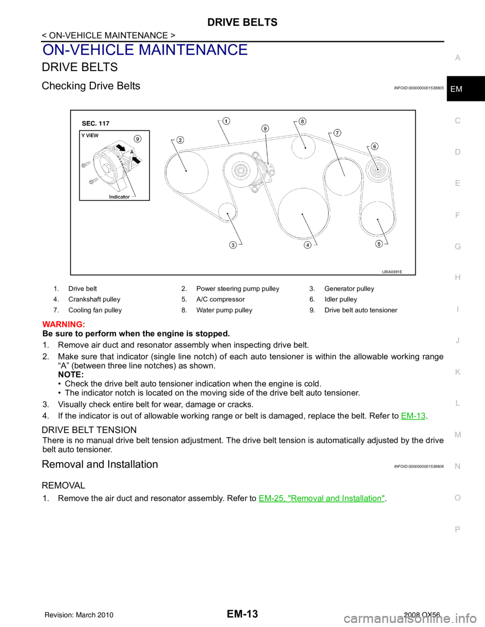
2. Make sure that indicator (single line notch) of eac
h auto tensioner is within the allowable working range
“A” (between three line notches) as shown.
NOTE:
• Check the drive belt auto tensioner indication when the engine is cold.
• The indicator notch is located on the moving side of the drive belt auto tensioner.
3. Visually check entire belt for wear, damage or cracks.
4. If the indicator is out of allowable working range or belt is damaged, replace the belt. Refer to EM-13
.
DRIVE BELT TENSION
There is no manual drive belt tension adjustment. The driv e belt tension is automatically adjusted by the drive
belt auto tensioner.
Removal and InstallationINFOID:0000000001538806
REMOVAL
1. Remove the air duct and resonator assembly. Refer to EM-25, "Removal and Installation".
1. Drive belt2. Power steering pump pulley 3. Generator pulley
4. Crankshaft pulley 5. A/C compressor6. Idler pulley
7. Cooling fan pulley 8. Water pump pulley9. Drive belt auto tensioner
LBIA0391E
Revision: March 2010 2008 QX56
Page 1829 of 4083
EM-26
< ON-VEHICLE REPAIR >
INTAKE MANIFOLD
INTAKE MANIFOLD
Removal and InstallationINFOID:0000000001538814
REMOVAL
1. Partially drain the engine coolant. Refer to CO-11, "Changing Engine Coolant".
WARNING:
To avoid the danger of being scal ded, never drain the engine coolant when the engine is hot.
2. Remove the engine room cover using power tool. Refer to EM-24, "
Removal and Installation".
3. Release the fuel pressure. Refer to EC-494, "
Fuel Pressure Check".
4. Remove the air duct and resonator assembly. Refer to EM-25, "
Removal and Installation".
5. Disconnect the fuel tube quick connector on the engine side.
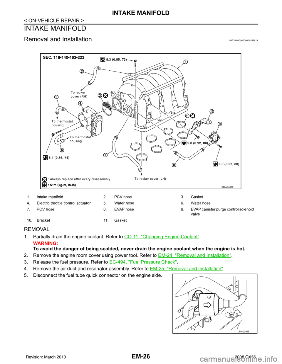
1. Intake manifold 2. PCV hose 3. Gasket
4. Electric throttle control actuator 5. Water hose 6. Water hose
7. PCV hose 8. EVAP hose 9. EVAP canister purge control solenoid
valve
10. Bracket 11. Gasket
KBIA2461E
LBIA0395E
Revision: March 2010 2008 QX56
Page 1833 of 4083
EM-30
< ON-VEHICLE REPAIR >
EXHAUST MANIFOLD AND THREE WAY CATALYST
EXHAUST MANIFOLD AND THREE WAY CATALYST
Exploded ViewINFOID:0000000006055156
Removal and InstallationINFOID:0000000006055157
REMOVAL
WARNING:
Perform the work when the exhaust and cooling system have cooled sufficiently.
1. Remove the engine undercover (rear) using power tool (4WD models).
2. Remove front final drive assembly (4WD models). Refer to DLN-212, "
Removal and Installation".
3. Remove the main muffler assembly and center exhaust tube. Refer to EX-6, "
Removal and Installation".
4. Remove the front exhaust tubes. Refer to EX-6, "
Removal and Installation".
5. Remove front tires. Refer to WT-48, "
Rotation".
6. Remove fender protectors. Refer to EXT-23, "
Removal and Installation".
7. Remove the LH and RH air fuel ratio A/F sensors. • Follow steps below to remove each air fuel ratio A/F sensor.
a. Remove the harness connector of each air fuel ra tio A/F sensor, and harness from bracket and middle
clamp.
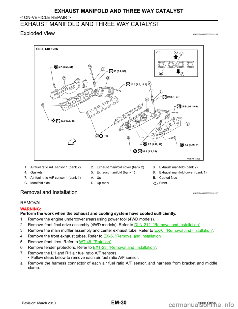
1. Air fuel ratio A/F sensor 1 (bank 2) 2. Exhaust manifold cover (bank 2) 3. Exhaust manifold (bank 2)
4. Gaskets 5. Exhaust manifold (bank 1) 6. Exhaust manifold cover (bank 1)
7. Air fuel ratio A/F sensor 1 (bank 1) A. Up B. Coated face
C. Manifold side D. Up mark Front
AWBIA0453GB
Revision: March 2010 2008 QX56
Page 1836 of 4083
OIL PAN AND OIL STRAINEREM-33
< ON-VEHICLE REPAIR >
C
DE
F
G H
I
J
K L
M A
EM
NP
O
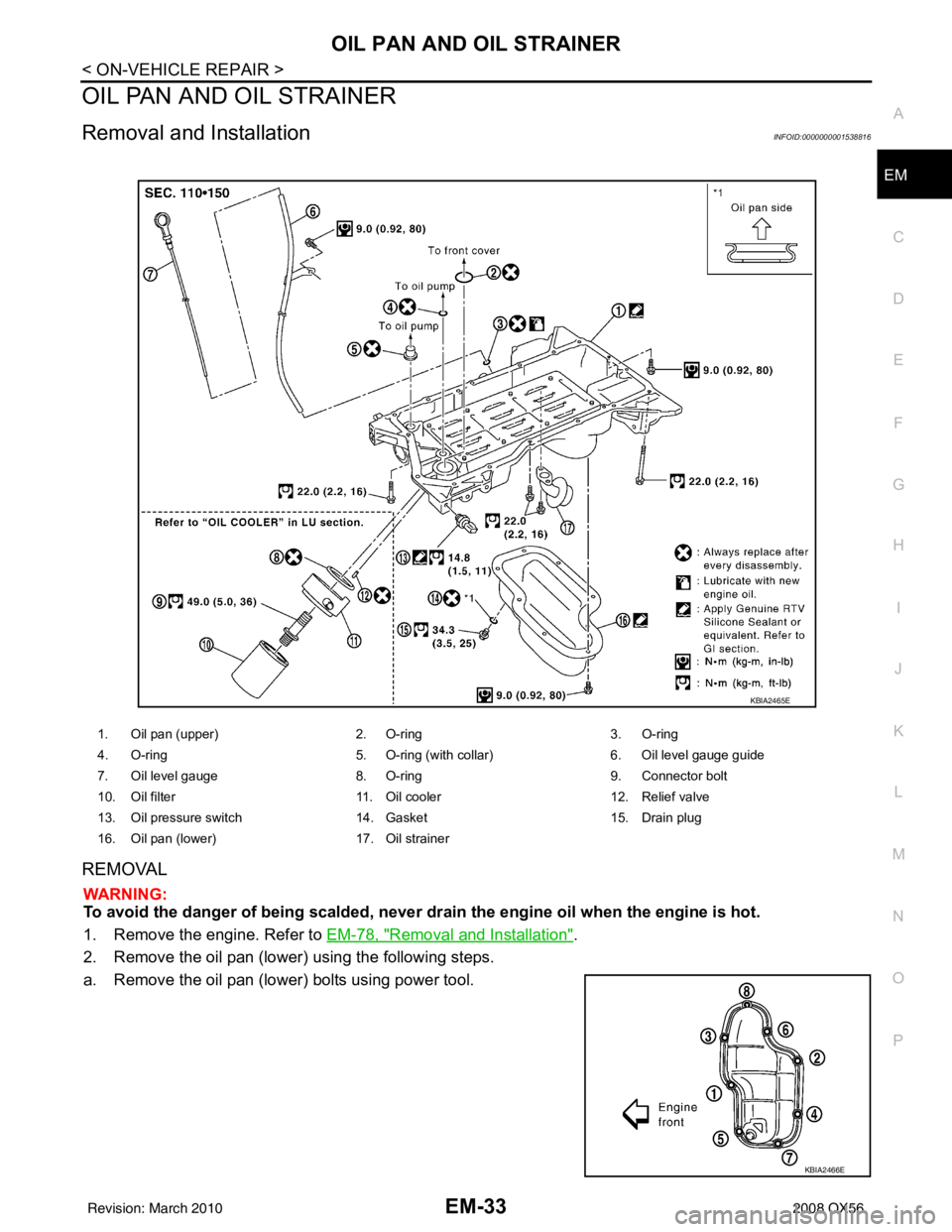
OIL PAN AND OIL STRAINER
Removal and InstallationINFOID:0000000001538816
REMOVAL
WARNING:
To avoid the danger of being scalded, never drain the engine oil when the engine is hot.
1. Remove the engine. Refer to
EM-78, "
Removal and Installation".
2. Remove the oil pan (lower) using the following steps.
a. Remove the oil pan (lower) bolts using power tool.
1. Oil pan (upper) 2. O-ring3. O-ring
4. O-ring 5. O-ring (with collar)6. Oil level gauge guide
7. Oil level gauge 8. O-ring9. Connector bolt
10. Oil filter 11. Oil cooler12. Relief valve
13. Oil pressure switch 14. Gasket15. Drain plug
16. Oil pan (lower) 17. Oil strainer
KBIA2465E
KBIA2466E
Revision: March 2010 2008 QX56