Page 1944 of 4083

EXL-16
< FUNCTION DIAGNOSIS >
TURN SIGNAL AND HAZARD WARNING LAMPS
TURN SIGNAL AND HAZARD WARNING LAMPS
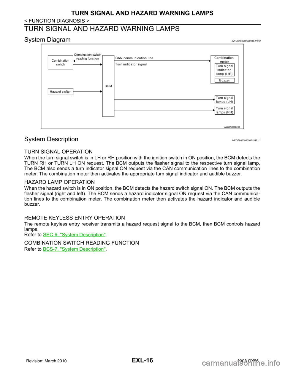
System DiagramINFOID:0000000001547110
System DescriptionINFOID:0000000001547111
TURN SIGNAL OPERATION
When the turn signal switch is in LH or RH position with the ignition switch in ON position, the BCM detects the
TURN RH or TURN LH ON request. The BCM outputs the flasher signal to the respective turn signal lamp.
The BCM also sends a turn indicator signal ON reques t via the CAN communication lines to the combination
meter. The combination meter then activates the appropriate turn signal indicator and audible buzzer.
HAZARD LAMP OPERATION
When the hazard switch is in ON position, the BCM det ects the hazard switch signal ON. The BCM outputs the
flasher signal (right and left). The BCM sends a hazar d indicator signal ON request via the CAN communica-
tion lines to the combination meter. The combination meter then activates the hazard indicator and audible
buzzer.
REMOTE KEYLESS ENTRY OPERATION
The remote keyless entry receiver transmits a hazar d request signal to the BCM, then BCM controls hazard
lamps.
Refer to SEC-9, "
System Description".
COMBINATION SWITCH READING FUNCTION
Refer to BCS-7, "System Description".
AWLIA0006GB
Revision: March 2010 2008 QX56
Page 1945 of 4083
TURN SIGNAL AND HAZARD WARNING LAMPSEXL-17
< FUNCTION DIAGNOSIS >
C
DE
F
G H
I
J
K
M A
B
EXL
N
O P
Component Parts LocationINFOID:0000000001547112
Component DescriptionINFOID:0000000001547113
1. Combination meter M24 2. Combination switch M283. Hazard switch M55
4. BCM M18, M20 (view with instrument panel removed)
ALLIA0384ZZ
Part name Description
BCM Controls turn signal and hazard flasher operation.
Combination switch Lighting and turn signal switch requests are output to the BCM.
Hazard switch Hazard flasher request signal is output to the BCM.
Combination meter Outputs turn and hazard indicator as requested by the BCM.
Revision: March 2010 2008 QX56
Page 1953 of 4083

DIAGNOSIS SYSTEM (BCM)EXL-25
< FUNCTION DIAGNOSIS >
C
DE
F
G H
I
J
K
M A
B
EXL
N
O P
1: The item is indicated, not monitored.
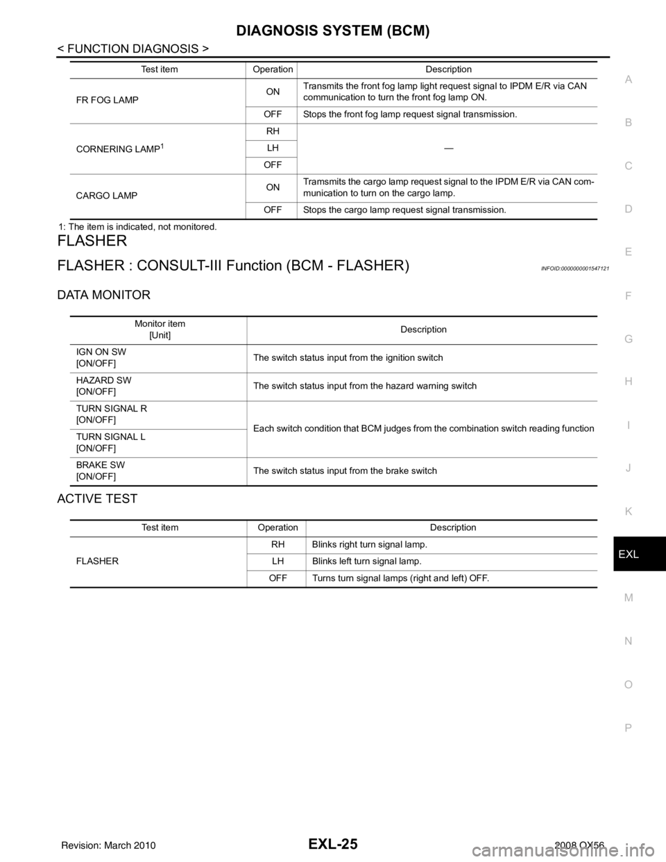
FLASHER
FLASHER : CONSULT-III Function (BCM - FLASHER)INFOID:0000000001547121
DATA MONITOR
ACTIVE TEST
FR FOG LAMP ON
Transmits the front fog lamp light request signal to IPDM E/R via CAN
communication to turn the front fog lamp ON.
OFF Stops the front fog lamp request signal transmission.
CORNERING LAMP
1
RH —
LH
OFF
CARGO LAMP ON
Tramsmits the cargo lamp request signal to the IPDM E/R via CAN com-
munication to turn on the cargo lamp.
OFF Stops the cargo lamp request signal transmission.
Test item
Operation Description
Monitor item
[Unit] Description
IGN ON SW
[ON/OFF] The switch status input from the ignition switch
HAZARD SW
[ON/OFF] The switch status input from the hazard warning switch
TURN SIGNAL R
[ON/OFF] Each switch condition that BCM judges from the combination switch reading function
TURN SIGNAL L
[ON/OFF]
BRAKE SW
[ON/OFF] The switch status input from the brake switch
Test item
Operation Description
FLASHER RH Blinks right turn signal lamp.
LH Blinks left turn signal lamp.
OFF Turns turn signal lamps (right and left) OFF.
Revision: March 2010 2008 QX56
Page 1965 of 4083

TURN SIGNAL LAMP CIRCUITEXL-37
< COMPONENT DIAGNOSIS >
C
DE
F
G H
I
J
K
M A
B
EXL
N
O P
TURN SIGNAL LAMP CIRCUIT
DescriptionINFOID:0000000001547137
The BCM monitors inputs from the combination switch to determine when to activate the turn signals. The
BCM outputs voltage direction to the left and right turn signals during turn signal operation or both during haz-
ard warning operation. The BCM sends a turn signal i ndicator request to the combination meter via the CAN
communication lines.
The BCM performs the fast flasher operation (fail-safe) if any bulb or harness of the turn signal lamp circuit is
open.
NOTE:
Turn signal lamp blinks at normal speed when using the hazard warning lamp.
Component Function CheckINFOID:0000000001547138
1.CHECK TURN SIGNAL LAMP
CONSULT-III
1. Select "FLASHER" of BCM (F LASHER) active test item.
2. With operating the test items, chec k that the turn signal lamp blinks.
Does the turn signal lamp blink?
YES >> Turn signal lamp circuit is normal.
NO >> Refer to EXL-37, "
Diagnosis Procedure".
Diagnosis ProcedureINFOID:0000000001547139
1.CHECK TURN SIGNAL LAMP BULB
Check the applicable lamp bulb to be sure the proper bulb standard is in use and the bulb is not open.
Is the bulb OK?
YES >> GO TO 2
NO >> Replace the bulb.
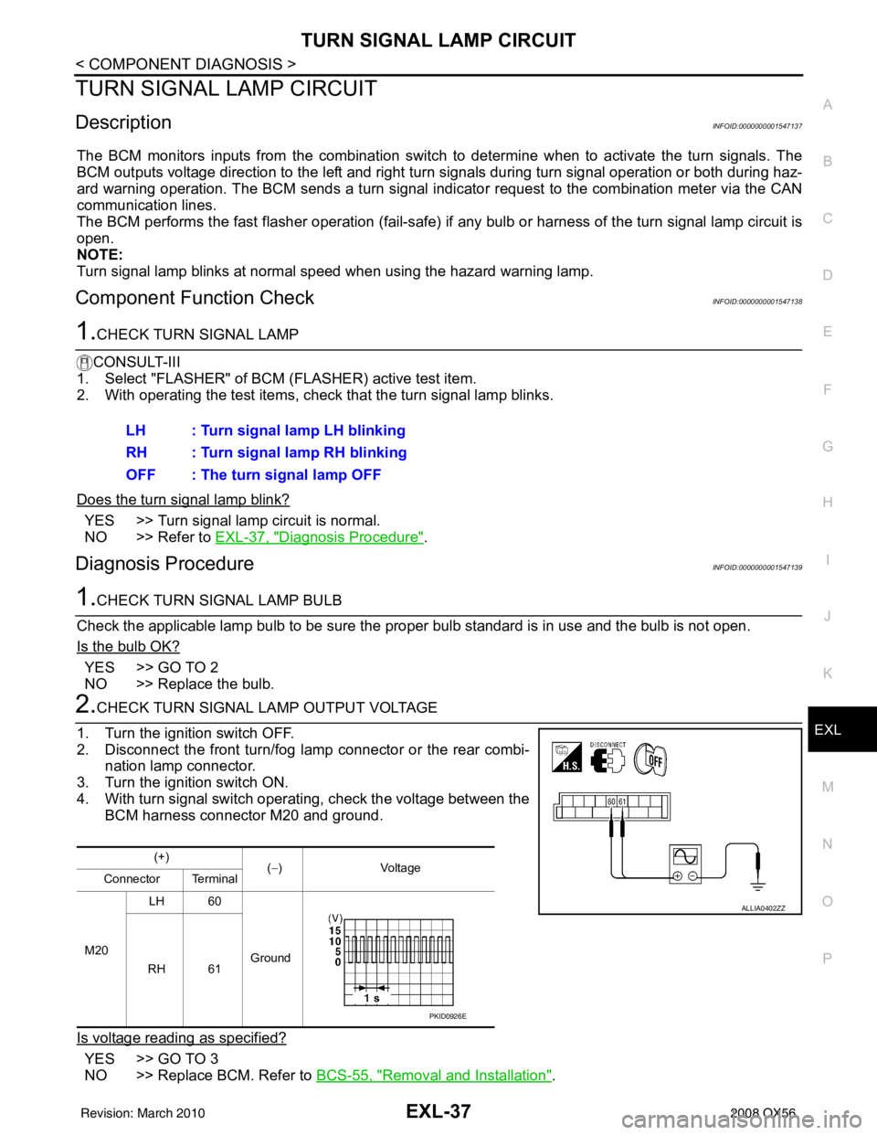
2.CHECK TURN SIGNAL LA MP OUTPUT VOLTAGE
1. Turn the ignition switch OFF.
2. Disconnect the front turn/fog lamp connector or the rear combi- nation lamp connector.
3. Turn the ignition switch ON.
4. With turn signal switch operating, check the voltage between the BCM harness connector M20 and ground.
Is voltage reading as specified?
YES >> GO TO 3
NO >> Replace BCM. Refer to BCS-55, "
Removal and Installation".
LH : Turn signal lamp LH blinking
RH : Turn signal lamp RH blinking
OFF : The turn signal lamp OFF
(+)
(−)V olt a g e
Connector Terminal
M20 LH 60
Ground
RH 61
ALLIA0402ZZ
PKID0926E
Revision: March 2010 2008 QX56
Page 1996 of 4083
EXL-68
< COMPONENT DIAGNOSIS >
TURN SIGNAL AND HAZARD WARNING LAMP SYSTEM
TURN SIGNAL AND HAZARD WARNING LAMP SYSTEM
Wiring DiagramINFOID:0000000001547147
AALWA0088GB
Revision: March 2010 2008 QX56
Page 1997 of 4083
TURN SIGNAL AND HAZARD WARNING LAMP SYSTEMEXL-69
< COMPONENT DIAGNOSIS >
C
DE
F
G H
I
J
K
M A
B
EXL
N
O P
ALLIA0519GB
Revision: March 2010 2008 QX56
Page 1998 of 4083
EXL-70
< COMPONENT DIAGNOSIS >
TURN SIGNAL AND HAZARD WARNING LAMP SYSTEM
AALIA0190GB
Revision: March 20102008 QX56
Page 1999 of 4083
TURN SIGNAL AND HAZARD WARNING LAMP SYSTEMEXL-71
< COMPONENT DIAGNOSIS >
C
DE
F
G H
I
J
K
M A
B
EXL
N
O P
AALIA0191GB
Revision: March 2010 2008 QX56