Page 3823 of 4083

TM-276
< DISASSEMBLY AND ASSEMBLY >
ASSEMBLY
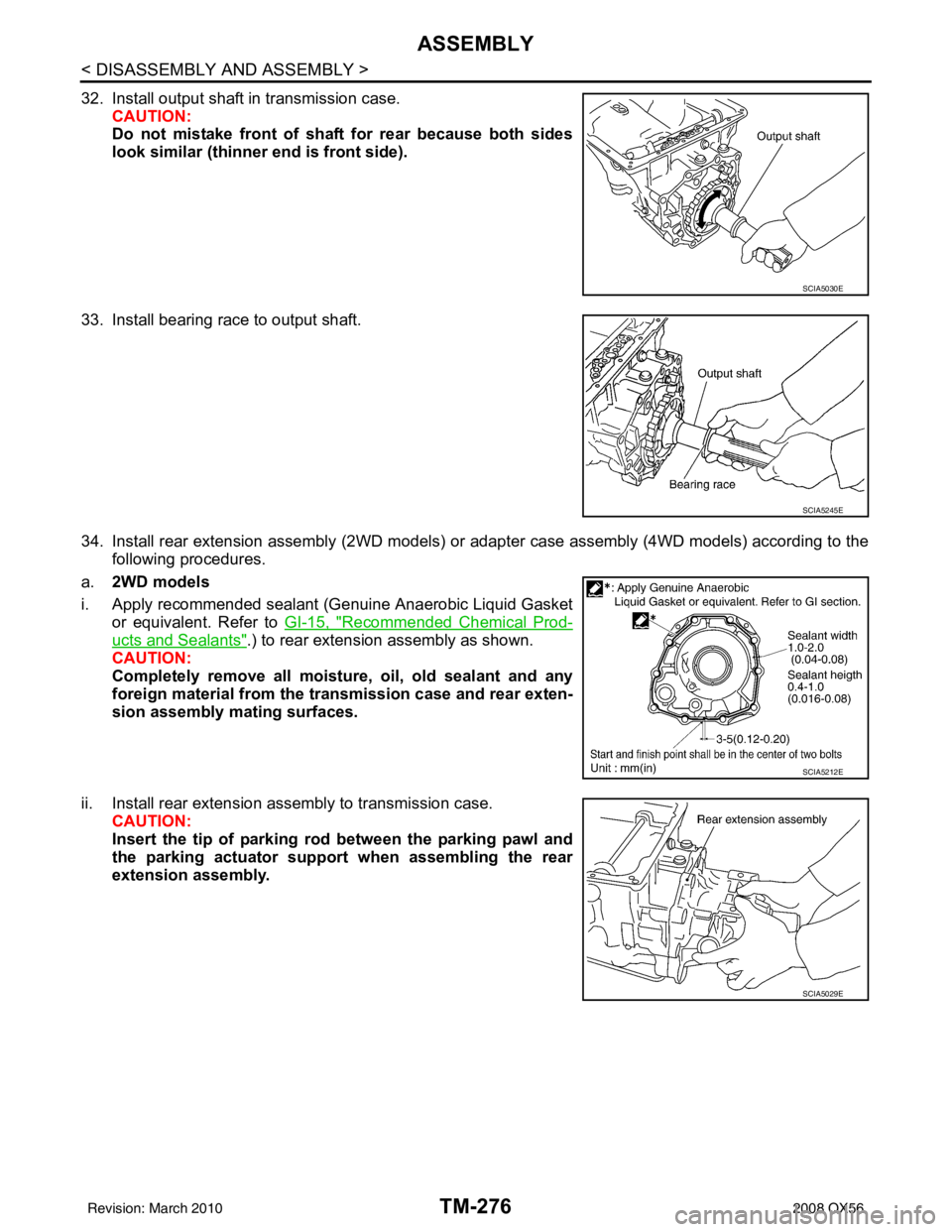
32. Install output shaft in transmission case.CAUTION:
Do not mistake front of shaft for rear because both sides
look similar (thinner end is front side).
33. Install bearing race to output shaft.
34. Install rear extension assembly (2WD models) or adapter case assembly (4WD models) according to the following procedures.
a. 2WD models
i. Apply recommended sealant (Genuine Anaerobic Liquid Gasket or equivalent. Refer to GI-15, "
Recommended Chemical Prod-
ucts and Sealants".) to rear extension assembly as shown.
CAUTION:
Completely remove all moisture, oil, old sealant and any
foreign material from the tr ansmission case and rear exten-
sion assembly mating surfaces.
ii. Install rear extension assembly to transmission case. CAUTION:
Insert the tip of parking rod between the parking pawl and
the parking actuator support when assembling the rear
extension assembly.
SCIA5030E
SCIA5245E
SCIA5212E
SCIA5029E
Revision: March 2010 2008 QX56
Page 3824 of 4083

ASSEMBLYTM-277
< DISASSEMBLY AND ASSEMBLY >
CEF
G H
I
J
K L
M A
B
TM
N
O P
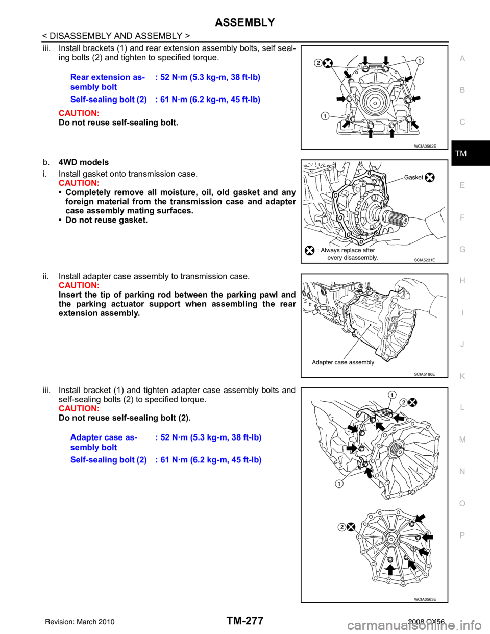
iii. Install brackets (1) and rear extension assembly bolts, self seal- ing bolts (2) and tighten to specified torque.
CAUTION:
Do not reuse self-sealing bolt.
b. 4WD models
i. Install gasket onto transmission case. CAUTION:
• Completely remove all moistu re, oil, old gasket and any
foreign material from the transmission case and adapter
case assembly mating surfaces.
• Do not reuse gasket.
ii. Install adapter case assembly to transmission case. CAUTION:
Insert the tip of parking rod between the parking pawl and
the parking actuator support when assembling the rear
extension assembly.
iii. Install bracket (1) and tighten adapter case assembly bolts and self-sealing bolts (2) to specified torque.
CAUTION:
Do not reuse self-sealing bolt (2).Rear extension as-
sembly bolt
: 52 N·m (5.3 kg-m, 38 ft-lb)
Self-sealing bolt (2) : 61 N·m (6.2 kg-m, 45 ft-lb)
WCIA0562E
SCIA5231E
SCIA5186E
Adapter case as-
sembly bolt : 52 N·m (5.3 kg-m, 38 ft-lb)
Self-sealing bolt (2) : 61 N·m (6.2 kg-m, 45 ft-lb)
WCIA0563E
Revision: March 2010 2008 QX56
Page 3838 of 4083

SERVICE DATA AND SPECIFICATIONS (SDS)TM-291
< SERVICE DATA AND SPECIFICATIONS (SDS)
CEF
G H
I
J
K L
M A
B
TM
N
O P
SERVICE DATA AND SPECIFICATIONS (SDS)
SERVICE DATA AND SPECIFICATIONS (SDS)
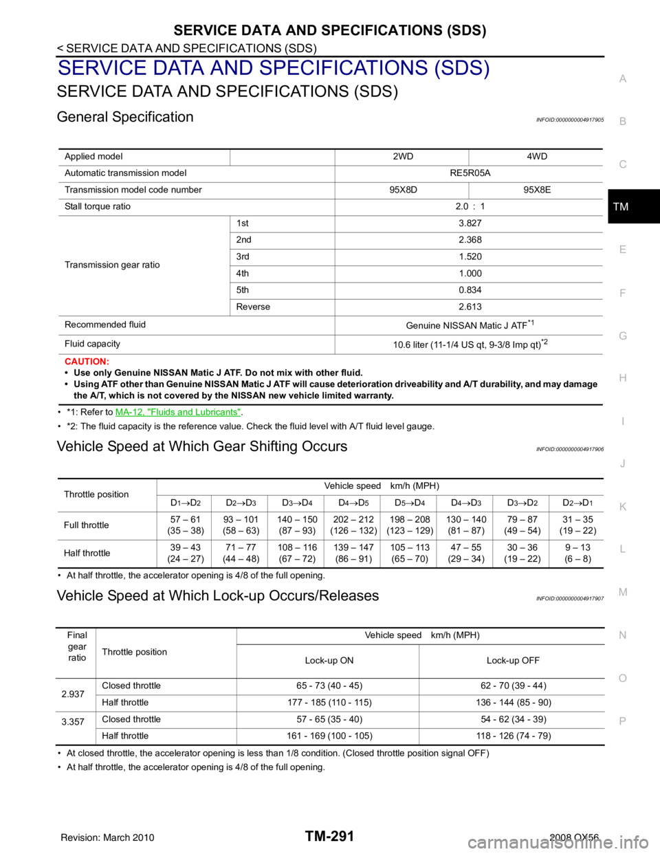
General SpecificationINFOID:0000000004917905
• *1: Refer to MA-12, "Fluids and Lubricants".
• *2: The fluid capacity is the reference value. Check the fluid level with A/T fluid level gauge.
Vehicle Speed at Which Gear Shifting OccursINFOID:0000000004917906
• At half throttle, the accelerator opening is 4/8 of the full opening.
Vehicle Speed at Which Lock-up Occurs/ReleasesINFOID:0000000004917907
• At closed throttle, the accelerator opening is less than 1/8 condition. (Closed throttle position signal OFF)
• At half throttle, the accelerator opening is 4/8 of the full opening. Applied model
2WD4WD
Automatic transmission model RE5R05A
Transmission model code number 95X8D95X8E
Stall torque ratio 2.0 : 1
Transmission gear ratio 1st
3.827
2nd 2.368
3rd 1.520
4th 1.000
5th 0.834
Reverse 2.613
Recommended fluid Genuine NISSAN Matic J ATF
*1
Fluid capacity10.6 liter (11-1/4 US qt, 9-3/8 Imp qt)*2
CAUTION:
• Use only Genuine NISSAN Matic J ATF. Do not mix with other fluid.
• Using ATF other than Genuine NISSAN Matic J ATF will cause deterioration driveability and A/ T durability, and may damage
the A/T, which is not covered by the NISSAN new vehicle limited warranty.
Throttle position Vehicle speed km/h (MPH)
D1→D2D2→ D3D3→D4D4→D5D5→D4D4→D3D3→D2D2→D1
Full throttle 57 – 61
(35 – 38) 93 – 101
(58 – 63) 140 – 150
(87 – 93) 202 – 212
(126 – 132) 198 – 208
(123 – 129) 130 – 140
(81 – 87) 79 – 87
(49 – 54) 31 – 35
(19 – 22)
Half throttle 39 – 43
(24 – 27) 71 – 77
(44 – 48) 108 – 116
(67 – 72) 139 – 147
(86 – 91) 105 – 113
(65 – 70) 47 – 55
(29 – 34) 30 – 36
(19 – 22) 9 – 13
(6 – 8)
Final gear ratio Throttle position Vehicle speed km/h (MPH)
Lock-up ON Lock-up OFF
2.937 Closed throttle
65 - 73 (40 - 45) 62 - 70 (39 - 44)
Half throttle 177 - 185 (110 - 115) 136 - 144 (85 - 90)
3.357 Closed throttle
57 - 65 (35 - 40) 54 - 62 (34 - 39)
Half throttle 161 - 169 (100 - 105) 118 - 126 (74 - 79)
Revision: March 2010 2008 QX56
Page 3892 of 4083

WCS
DIAGNOSIS SYSTEM (METER)WCS-15
< FUNCTION DIAGNOSIS >
C
DE
F
G H
I
J
K L
M B A
O P
NOTE:
Some items are not available due to vehicle specification.
*: The monitor will indicate “OFF” even though the brake warnin g lamp is on if either of the following conditions exist.
• The parking brake is engaged
• The brake fluid level is low CRUISE W/L [ON/OFF]
X Indicates [ON/OFF] condition of CRUISE warning lamp.
4WD LOCK SW [ON/OFF] X Indicates [ON/OFF] condition of 4WD lock switch.
4WD LOCK IND [ON/OFF] X Indicates [ON/OFF] condition of 4WD lock indicator.
SEAT BELT W/L [ON/OFF] X Indicates [ON/OFF] condition of seat belt warning lamp.
FR FOG IND [ON/OFF] X This item is not used for this model. “OFF” is always displayed.
RR FOG IND [ON/OFF] X This item is not used for this model. “OFF” is always displayed.
LIGHT IND [ON/OFF] X Indicates [ON/OFF] condition of light indicator.
PNP P SW [ON/OFF] XX Indicates [ON/OFF] co ndition of transmission range P switch.
PNP N SW [ON/OFF] XX Indicates [ON/OFF] condition of transmission range N switch.
4WD W/L [ON/OFF] X Indicates [ON/OFF] condition of 4WD warning lamp.
Display item [Unit]
MAIN
SIGNALS SELECTION
FROM MENU Description
Revision: March 2010
2008 QX56
Page 3926 of 4083

WCS
COMBINATION METERWCS-49
< ECU DIAGNOSIS >
C
DE
F
G H
I
J
K L
M B A
O P
DTC IndexINFOID:0000000004871171
Function Specifications
Speedometer
Zero indication.
Tachometer
Fuel gauge
Engine coolant temperature gauge
Engine oil pressure gauge
Voltage gauge
A/T oil temperature gauge
Illumination control
Meter illumination Change to nighttime mode when communication is lost.
Segment LCD Odometer
Freeze current indication.
A/T position Display turns off.
Buzzer Buzzer turns off.
Warning lamp/indicator lamp ABS warning lamp
Lamp turns on when communication is lost.
Brake warning lamp
VDC OFF indicator lamp
SLIP indicator lamp
A/T CHECK warning lamp
Lamp turns off when communication is lost.
Oil pressure/coolant temperature
warning lamp
Light indicator
Malfunction indicator lamp
Master warning lamp
Air bag warning lamp
High beam indicator
Turn signal indicator lamp
CRUISE indicator lamp
Driver and passenger seat belt warn-
ing lamp
Lamp turns off when disconnected.
Charge warning lamp
Security indicator lamp
4WD indicator lamp
ATP indicator lamp
CK SUSP warning lamp
Low tire pressu
re warning lamp Lamp will flash every second for 1 minute and then stay on con-
tinuously thereafter.
CONSULT-III display
MalfunctionReference
page
CAN COMM CIRC
[U1000] Malfunction is detected in CAN communication.
CAUTION:
Even when there is no ma
lfunction on CAN communication system, malfunction may be
misinterpreted when battery has low voltag e (when maintaining 7 - 8 V for about 2 sec-
onds) or 10A fuse [No. 19, located in the fuse block (J/B)] is disconnected. MWI-28
VEHICLE SPEED
CIRC
[B2205]Malfunction is detected when an erroneous speed signal is input.
CAUTION:
Even when there is no malfunction on speed signal system, malfunction may be misin-
terpreted when battery has low voltage (whe
n maintaining 7 - 8 V for about 2 seconds). MWI-29
Revision: March 2010
2008 QX56