2008 INFINITI QX56 tow
[x] Cancel search: towPage 1835 of 4083
EM-32
< ON-VEHICLE REPAIR >
EXHAUST MANIFOLD AND THREE WAY CATALYST
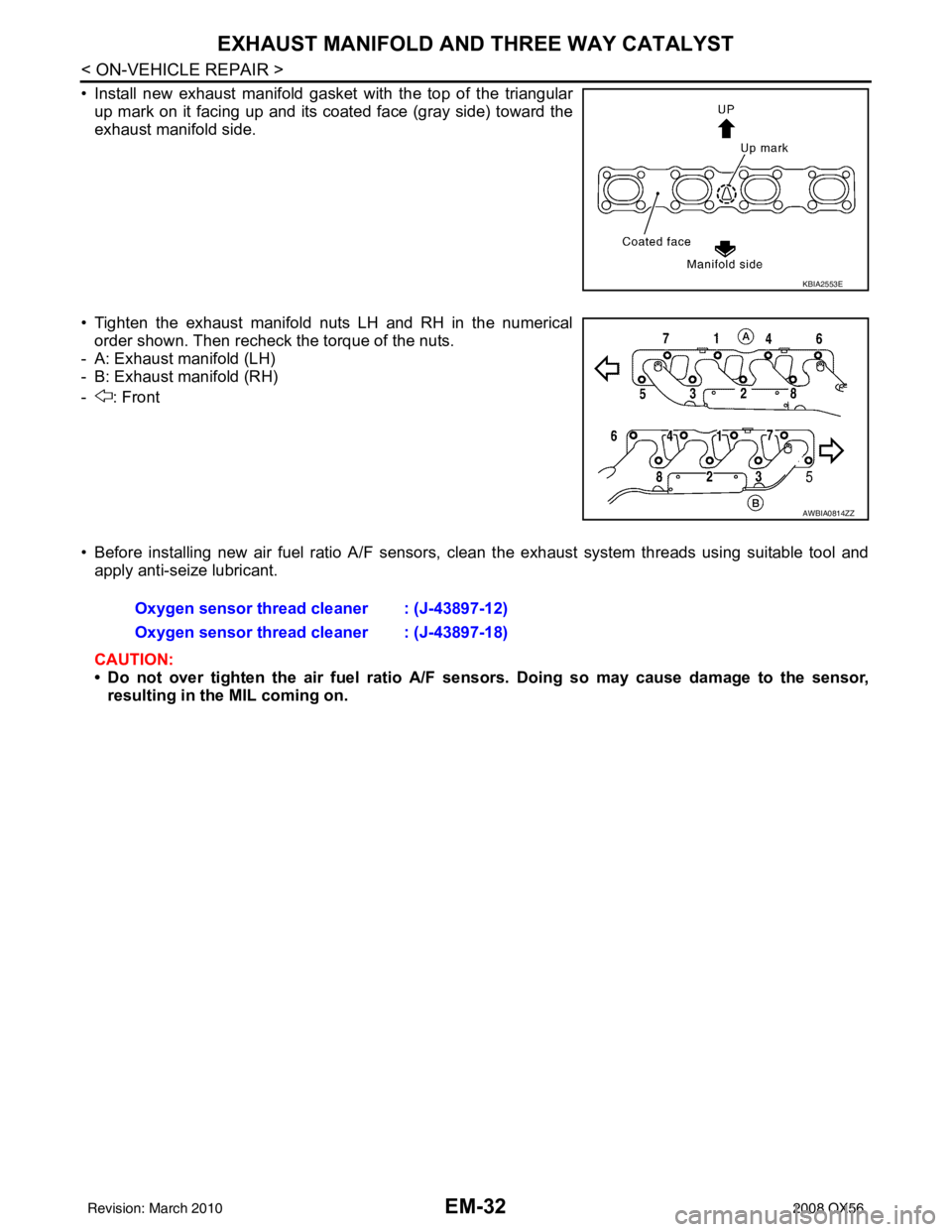
• Install new exhaust manifold gasket with the top of the triangularup mark on it facing up and its coated face (gray side) toward the
exhaust manifold side.
• Tighten the exhaust manifold nuts LH and RH in the numerical order shown. Then recheck the torque of the nuts.
- A: Exhaust manifold (LH)
- B: Exhaust manifold (RH)
- : Front
• Before installing new air fuel ratio A/F sensors, clean the exhaust system threads using suitable tool and
apply anti-seize lubricant.
CAUTION:
• Do not over tighten the air fuel ratio A/F se nsors. Doing so may cause damage to the sensor,
resulting in the MIL coming on.
KBIA2553E
AWBIA0814ZZ
Oxygen sensor thread cleaner : (J-43897-12)
Oxygen sensor thread cleaner : (J-43897-18)
Revision: March 2010 2008 QX56
Page 1929 of 4083
EXL-1
DRIVER CONTROLS
C
DE
F
G H
I
J
K
M
SECTION EXL
A
B
EXL
N
O P
CONTENTS
EXTERIOR LIGHTING SYSTEM
BASIC INSPECTION ....... .............................4
DIAGNOSIS AND REPAIR WORKFLOW ..... .....4
Work Flow ........................................................... ......4
FUNCTION DIAGNOSIS ...............................7
HEADLAMP .................................................... .....7
System Diagram .................................................. ......7
System Description ...................................................7
Component Parts Location ........................................7
Component Description .............................................7
DAYTIME LIGHT SYSTEM .................................9
System Diagram .................................................. ......9
System Description ...................................................9
Component Parts Location ........................................9
Component Description ...........................................10
AUTO LIGHT SYSTEM ......................................11
System Diagram ......................................................11
System Description .................................................11
Component Parts Location ......................................12
Component Description ...........................................12
HEADLAMP AIMING SYSTEM (MANUAL) .......14
System Diagram .................................................. ....14
System Description .................................................14
Component Description ...........................................14
FRONT FOG LAMP ............................................15
System Diagram .................................................. ....15
System Description .................................................15
Component Parts Location ......................................15
Component Description ...........................................15
TURN SIGNAL AND HAZARD WARNING
LAMPS ...............................................................
16
System Diagram .................................................. ....16
System Description .................................................16
Component Parts Location ......................................17
Component Description ...........................................17
PARKING, LICENSE PLATE AND TAIL
LAMPS ..............................................................
18
System Diagram .................................................. ....18
System Description ..................................................18
Component Parts Location ......................................18
Component Description ...........................................19
TRAILER TOW ..................................................20
System Diagram ......................................................20
System Description ..................................................20
Component Parts Location ......................................21
Component Description ...........................................21
DIAGNOSIS SYSTEM (BCM) ...........................23
COMMON ITEM ..................................................... ....23
COMMON ITEM : Diagnosis Description ................23
COMMON ITEM : CONSULT-III Function ...............23
EXTERNAL LAMP ................................................. ....23
EXTERNAL LAMP : CONSULT-III Function ............23
FLASHER ............................................................... ....25
FLASHER : CONSULT-III Function (BCM -
FLASHER) ...............................................................
25
DIAGNOSIS SYSTEM (IPDM E/R) ...................26
CONSULT - III Function (IPDM E/R) .......................26
COMPONENT DIAGNOSIS .........................27
POWER SUPPLY AND GROUND CIRCUIT ....27
BCM (BODY CONTROL MODULE) ...................... ....27
BCM (BODY CONTROL MODULE) : Diagnosis
Procedure ............................................................ ....
27
IPDM E/R (INTELLIGENT POWER DISTRIBU-
TION MODULE ENGINE ROOM) .......................... ....
27
IPDM E/R (INTELLIGENT POWER DISTRIBU-
TION MODULE ENGINE ROOM) : Diagnosis Pro-
cedure .................................................................. ....
27
Revision: March 2010 2008 QX56
Page 1930 of 4083

EXL-2
HEADLAMP (HI) CIRCUIT ................................28
Description ........................................................... ...28
Component Function Check ...................................28
Diagnosis Procedure ..............................................28
HEADLAMP (LO) CIRCUIT ...............................30
Description ........................................................... ...30
Component Function Check ...................................30
Diagnosis Procedure ..............................................30
FRONT FOG LAMP CIRCUIT ...........................32
Description ........................................................... ...32
Component Function Check ...................................32
Diagnosis Procedure ..............................................32
PARKING LAMP CIRCUIT ................................34
Description ........................................................... ...34
Component Function Check ...................................34
Diagnosis Procedure ..............................................34
TURN SIGNAL LAMP CIRCUIT ........................37
Description ........................................................... ...37
Component Function Check ...................................37
Diagnosis Procedure ..............................................37
OPTICAL SENSOR ...........................................40
Description ..............................................................40
Component Function Check ...................................40
Diagnosis Procedure ..............................................40
HEADLAMP AIMING SWITCH ..........................42
Description ........................................................... ...42
Diagnosis Procedure ..............................................42
HEADLAMP .......................................................43
Wiring Diagram .................................................... ...43
DAYTIME LIGHT SYSTEM ................................47
Wiring Diagram .................................................... ...47
AUTO LIGHT SYSTEM ......................................54
Wiring Diagram .................................................... ...54
HEADLAMP AIMING SYSTEM (MANUAL) ......61
Wiring Diagram .................................................... ...61
FRONT FOG LAMP SYSTEM ...........................65
Wiring Diagram .................................................... ...65
TURN SIGNAL AND HAZARD WARNING
LAMP SYSTEM .............................................. ...
68
Wiring Diagram .................................................... ...68
PARKING, LICENSE PLATE AND TAIL
LAMPS SYSTEM ............................................ ...
75
Wiring Diagram .................................................... ...75
STOP LAMP ......................................................81
Wiring Diagram .................................................... ...81
BACK-UP LAMP ................................................85
Wiring Diagram .................................................... ...85
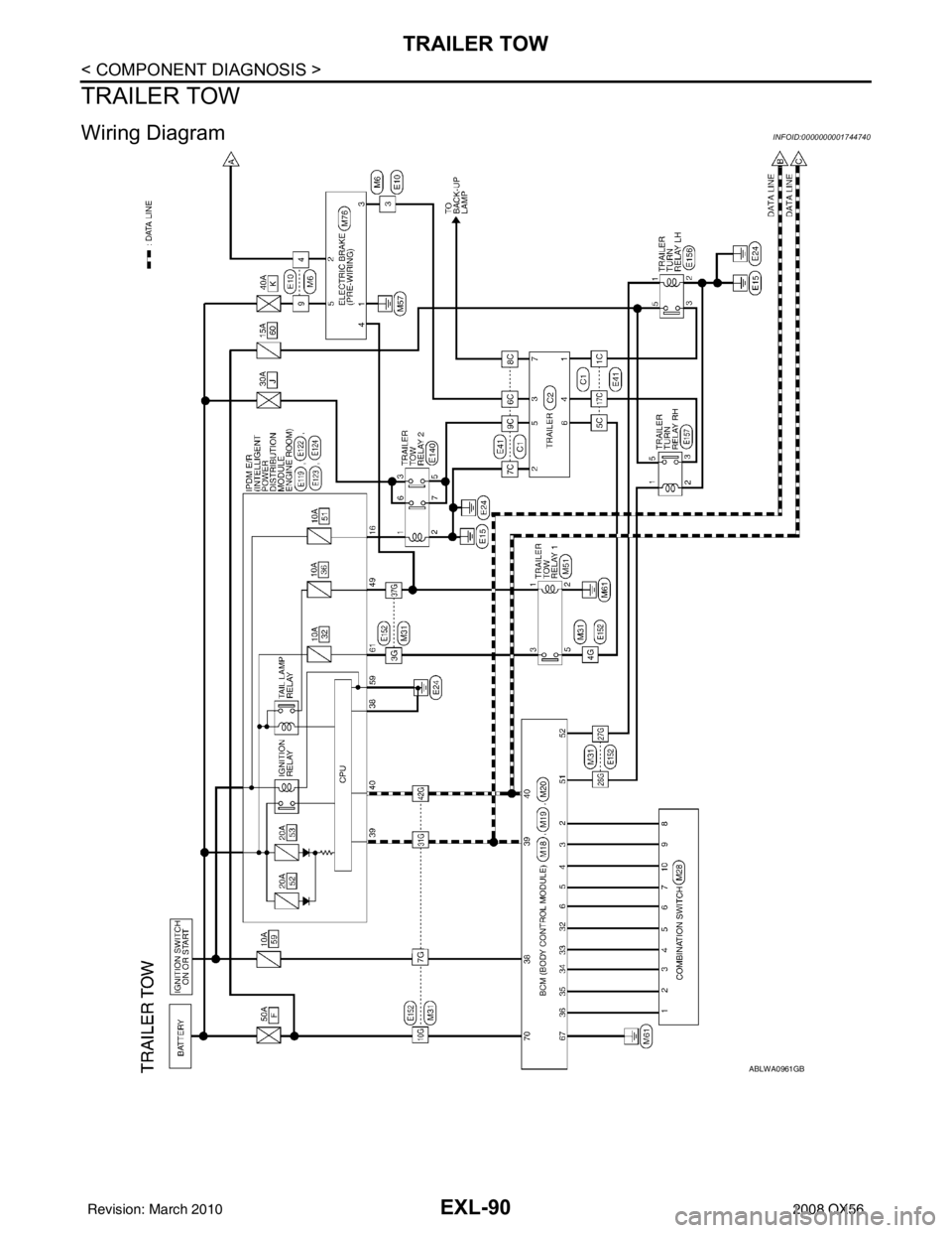
TRAILER TOW ..................................................90
Wiring Diagram .................................................... ...90
ECU DIAGNOSIS .......................................99
BCM (BODY CONTROL MODULE) ............... ...99
Description ........................................................... ...99
IPDM E/R (INTELLIGENT POWER DISTRI-
BUTION MODULE ENGINE ROOM) ................
100
Description ........................................................... .100
SYMPTOM DIAGNOSIS ...........................101
EXTERIOR LIGHTING SYSTEM SYMPTOMS ..101
Symptom Table .................................................... .101
NORMAL OPERATING CONDITION ...............103
Description ........................................................... .103
BOTH SIDE HEADLAMPS DO NOT SWITCH
TO HIGH BEAM ................................................
104
Description ........................................................... .104
Diagnosis Procedure .............................................104
BOTH SIDE HEADLAMPS (LO) ARE NOT
TURNED ON .....................................................
105
Description ............................................................105
Diagnosis Procedure .............................................105
PARKING, LICENSE PLATE AND TAIL
LAMPS ARE NOT TURNED ON ......................
106
Description ........................................................... .106
Diagnosis Procedure .............................................106
BOTH SIDE FRONT FOG LAMPS ARE NOT
TURNED ON .....................................................
107
Description ............................................................107
Diagnosis Procedure .............................................107
PRECAUTION ...........................................108
PRECAUTIONS .............................................. ..108
Precaution for Supplemental Restraint System
(SRS) "AIR BAG" and "SEAT BELT PRE-TEN-
SIONER" .............................................................. .
108
Precaution Necessary for Steering Wheel Rota-
tion After Battery Disconnect ................................
108
ON-VEHICLE REPAIR ..............................110
ADJUSTMENT AND INSPECTION ................ ..110
HEADLAMP ............................................................ .110
HEADLAMP : Aiming Adjustment .........................110
FRONT FOG LAMP ................................................ .111
FRONT FOG LAMP : Aiming Adjustment .............111
REMOVAL AND INSTALLATION .............113
HEADLAMP .................................................... ..113
Revision: March 2010 2008 QX56
Page 1936 of 4083
EXL-8
< FUNCTION DIAGNOSIS >
HEADLAMP
mixtureof xenon (an inert gas) and certain other metal halides. In addition to added lighting power, electronic
controlof the power supply gives the headlamps stable quality and tone color.Following are some of the many
advantages of the xenon type headlamp.
• The light produced by the headlamps is a white color comparable to sunlight that is easy on the eyes.
• Light output is nearly double that of halogen headlamps, affording increased area of illumination.
• The light features a high relative spectral distribution at wavelengths to which the human eye is most sensi-tive. This means that even in the rain, more light is reflected back from the road surface toward the vehi-
cle,for added visibility.
• Power consumption is approximately 25 percent less than halogen headlamps, reducing battery load..
HIGH BEAM OPERATION/FLASH-TO-PASS OPERATION
With the lighting switch in the 2ND position and placed in HIGH position, the BCM receives input requesting
the headlamp high beams to illuminate. The flash to pass feature can be used any time and also sends a sig-
nal to the BCM. This input is communicated to t he IPDM E/R via the CAN communication lines. The CPU of
the combination meter controls the ON/OFF status off the HIGH BEAM indicator. The CPU of the IPDM E/R
controls the headlamp high relay coil which supplies power to the high beam headlamps.
The combination meter receives a high beam request signal (ON) via the CAN communication lines and turns
the high beam indicator lamp ON.
COMBINATION SWITCH READING FUNCTION
Refer to BCS-7, "System Description".
AUTO LIGHT OPERATION
Refer to EXL-11, "System Description".
Revision: March 2010 2008 QX56
Page 1948 of 4083
EXL-20
< FUNCTION DIAGNOSIS >
TRAILER TOW
TRAILER TOW
System DiagramINFOID:0000000006095108
System DescriptionINFOID:0000000006095109
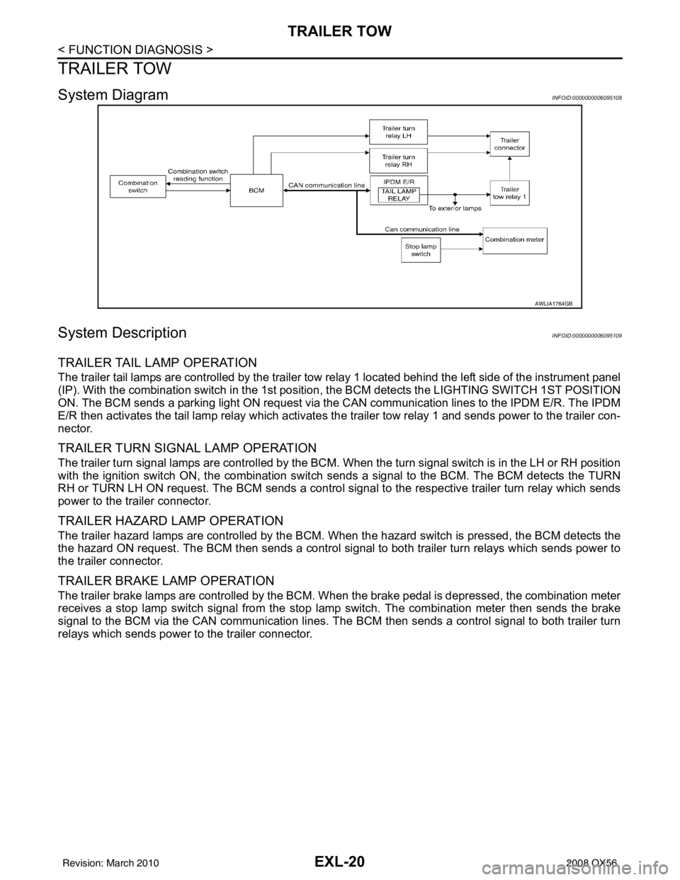
TRAILER TAIL LAMP OPERATION
The trailer tail lamps are controlled by the trailer tow relay 1 located behind the left side of the instrument panel
(IP). With the combination switch in the 1st position, the BCM detects the LIGHTING SWITCH 1ST POSITION
ON. The BCM sends a parking light ON request via the CAN communication lines to the IPDM E/R. The IPDM
E/R then activates the tail lamp relay which activates the trailer tow relay 1 and sends power to the trailer con-
nector.
TRAILER TURN SIGNAL LAMP OPERATION
The trailer turn signal lamps are controlled by the BCM. When the turn signal switch is in the LH or RH position
with the ignition switch ON, the combination switch sends a signal to the BCM. The BCM detects the TURN
RH or TURN LH ON request. The BCM sends a control signal to the respective trailer turn relay which sends
power to the trailer connector.
TRAILER HAZARD LAMP OPERATION
The trailer hazard lamps are controlled by the BCM. W hen the hazard switch is pressed, the BCM detects the
the hazard ON request. The BCM then sends a control si gnal to both trailer turn relays which sends power to
the trailer connector.
TRAILER BRAKE LAMP OPERATION
The trailer brake lamps are controlled by the BCM. When the brake pedal is depressed, the combination meter
receives a stop lamp switch signal from the stop lamp switch. The combination meter then sends the brake
signal to the BCM via the CAN communication lines. The BCM then sends a control signal to both trailer turn
relays which sends power to the trailer connector.
AWLIA1764GB
Revision: March 2010 2008 QX56
Page 1949 of 4083
TRAILER TOWEXL-21
< FUNCTION DIAGNOSIS >
C
DE
F
G H
I
J
K
M A
B
EXL
N
O P
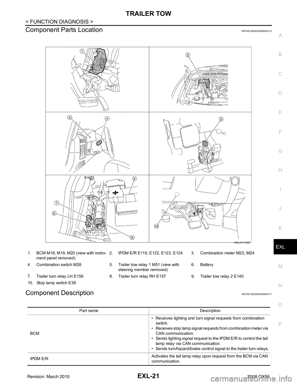
Component Parts LocationINFOID:0000000006095110
Component DescriptionINFOID:0000000006095111
1. BCM M18, M19, M20 (view with instru- ment panel removed) 2. IPDM E/R E119, E122, E123, E124 3. Combination meter M23, M24
4. Combination switch M28 5. Trailer tow relay 1 M51 (view with
steering member removed) 6. Battery
7. Trailer turn relay LH E156 8. Trailer turn relay RH E157 9. Trailer tow relay 2 E140
10. Stop lamp switch E38
AWLIA1772ZZ
Part name Description
BCM • Receives lighting and turn signal requests from combination
switch.
• Receives stop lamp signal requests from combination meter via CAN communication.
• Sends lighting signal request to the IPDM E/R to control the tail
lamp relay via CAN communication.
• Sends turn/hazard/brake control signal to the trailer turn relays.
IPDM E/R Activates the tail lamp relay upon request from the BCM via CAN
communication.
Revision: March 2010
2008 QX56
Page 1950 of 4083

EXL-22
< FUNCTION DIAGNOSIS >
TRAILER TOW
Combination meter• Receives stop lamp switch signal from stop lamp switch.
• Sends stop lamp signal request to the BCM via CAN communi-
cation.
Combination switch Outputs lighting and turn signal requests to the BCM.
Revision: March 2010 2008 QX56
Page 2018 of 4083
EXL-90
< COMPONENT DIAGNOSIS >
TRAILER TOW
TRAILER TOW
Wiring DiagramINFOID:0000000001744740
ABLWA0961GB
Revision: March 20102008 QX56