2008 INFINITI QX56 tow
[x] Cancel search: towPage 2812 of 4083
PG
HARNESSPG-45
< COMPONENT DIAGNOSIS >
C
DE
F
G H
I
J
K L
B A
O P
N
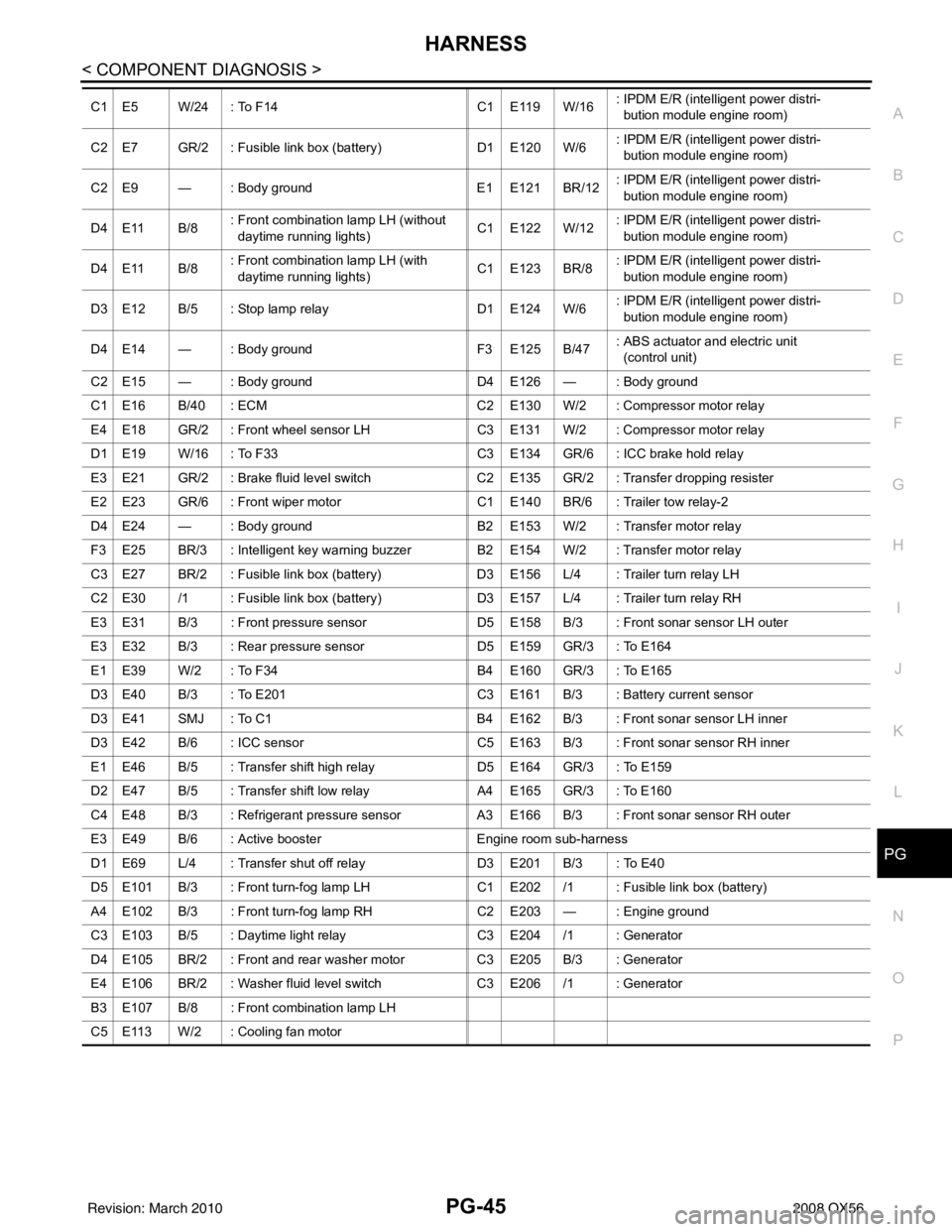
C1 E5 W/24 : To F14
C1 E119 W/16: IPDM E/R (intelligent power distri-
bution module engine room)
C2 E7 GR/2 : Fusible link box (battery) D1 E120 W/6: IPDM E/R (intelligent power distri-
bution module engine room)
C2 E9 — : Body ground E1 E121 BR/12: IPDM E/R (intelligent power distri-
bution module engine room)
D4 E11 B/8 : Front combination lamp LH (without
daytime running lights) C1 E122 W/12: IPDM E/R (intelligent power distri-
bution module engine room)
D4 E11 B/8 : Front combination lamp LH (with
daytime running lights)
C1 E123 BR/8: IPDM E/R (intelligent power distri-
bution module engine room)
D3 E12 B/5 : Stop lamp relay D1 E124 W/6: IPDM E/R (intelligent power distri-
bution module engine room)
D4 E14 — : Body ground F3 E125 B/47: ABS actuator and electric unit
(control unit)
C2 E15 — : Body ground D4 E126 — : Body ground
C1 E16 B/40 : ECM C2 E130 W/2 : Compressor motor relay
E4 E18 GR/2 : Front wheel sensor LH C3 E131 W/2 : Compressor motor relay
D1 E19 W/16 : To F33 C3 E134 GR/6 : ICC brake hold relay
E3 E21 GR/2 : Brake fluid level switch C2 E135 GR/2 : Transfer dropping resister
E2 E23 GR/6 : Front wiper motor C1 E140 BR/6 : Trailer tow relay-2
D4 E24 — : Body ground B2 E153 W/2 : Transfer motor relay
F3 E25 BR/3 : Intelligent key warning buzzer B2 E154 W/2 : Transfer motor relay
C3 E27 BR/2 : Fusible link box (battery) D3 E156 L/4 : Trailer turn relay LH
C2 E30 /1 : Fusible link box (battery )D3 E157 L/4 : Trailer turn relay RH
E3 E31 B/3 : Front pressure sensor D5 E158 B/3 : Front sonar sensor LH outer
E3 E32 B/3 : Rear pressure sensor D5 E159 GR/3 : To E164
E1 E39 W/2 : To F34 B4 E160 GR/3 : To E165
D3 E40 B/3 : To E201 C3 E161 B/3 : Battery current sensor
D3 E41 SMJ : To C1 B4 E162 B/3 : Front sonar sensor LH inner
D3 E42 B/6 : ICC sensor C5 E163 B/3 : Front sonar sensor RH inner
E1 E46 B/5 : Transfer shift high relay D5 E164 GR/3 : To E159
D2 E47 B/5 : Transfer shift lo w relayA4 E165 GR/3 : To E160
C4 E48 B/3 : Refrigerant pressure sensor A3 E166 B/3 : Front sonar sensor RH outer
E3 E49 B/6 : Active booster Engine room sub-harness
D1 E69 L/4 : Transfer shut off relay D3 E201 B/3 : To E40
D5 E101 B/3 : Front turn-fog lamp LH C1 E202 /1 : Fusible link box (battery)
A4 E102 B/3 : Front turn-fog lamp RH C2 E203 — : Engine ground
C3 E103 B/5 : Daytime light relay C3 E204 /1 : Generator
D4 E105 BR/2 : Front and rear washer motor C3 E205 B/3 : Generator
E4 E106 BR/2 : Washer fluid level switch C3 E206 /1 : Generator
B3 E107 B/8 : Front combination lamp LH
C5 E113 W/2 : Cooling fan motor
Revision: March 2010 2008 QX56
Page 2980 of 4083
RAX-12
< DISASSEMBLY AND ASSEMBLY >
REAR DRIVE SHAFT
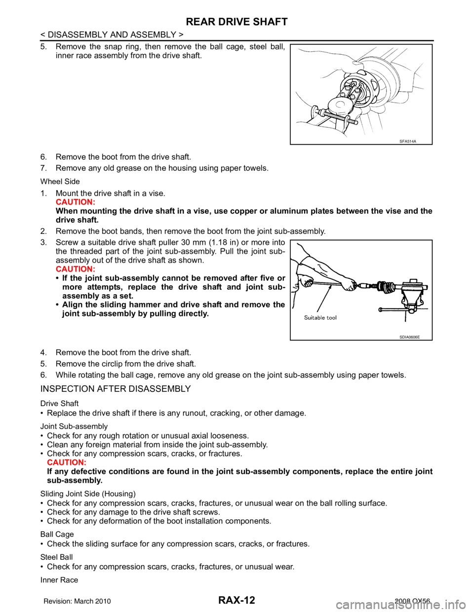
5. Remove the snap ring, then remove the ball cage, steel ball,inner race assembly from the drive shaft.
6. Remove the boot from the drive shaft.
7. Remove any old grease on the housing using paper towels.
Wheel Side
1. Mount the drive shaft in a vise. CAUTION:
When mounting the drive shaft in a vise, use copp er or aluminum plates between the vise and the
drive shaft.
2. Remove the boot bands, then remove the boot from the joint sub-assembly.
3. Screw a suitable drive shaft puller 30 mm (1.18 in) or more into the threaded part of the joint sub-assembly. Pull the joint sub-
assembly out of the drive shaft as shown.
CAUTION:
• If the joint sub-assembly cannot be removed after five ormore attempts, replace the drive shaft and joint sub-
assembly as a set.
• Align the sliding hammer and drive shaft and remove the
joint sub-assembly by pulling directly.
4. Remove the boot from the drive shaft.
5. Remove the circlip from the drive shaft.
6. While rotating the ball cage, remove any old grease on the joint sub-assembly using paper towels.
INSPECTION AFTER DISASSEMBLY
Drive Shaft
• Replace the drive shaft if there is any runout, cracking, or other damage.
Joint Sub-assembly
• Check for any rough rotation or unusual axial looseness.
• Clean any foreign material from inside the joint sub-assembly.
• Check for any compression scars, cracks, or fractures.
CAUTION:
If any defective conditions are found in the joint sub-assembly comp onents, replace the entire joint
sub-assembly.
Sliding Joint Side (Housing)
• Check for any compression scars, cracks, fracture s, or unusual wear on the ball rolling surface.
• Check for any damage to the drive shaft screws.
• Check for any deformation of the boot installation components.
Ball Cage
• Check the sliding surface for any compression scars, cracks, or fractures.
Steel Ball
• Check for any compression scars, cr acks, fractures, or unusual wear.
Inner Race
SFA514A
SDIA0606E
Revision: March 2010 2008 QX56
Page 3053 of 4083
RSU-14
< REMOVAL AND INSTALLATION >
REAR SUSPENSION MEMBER
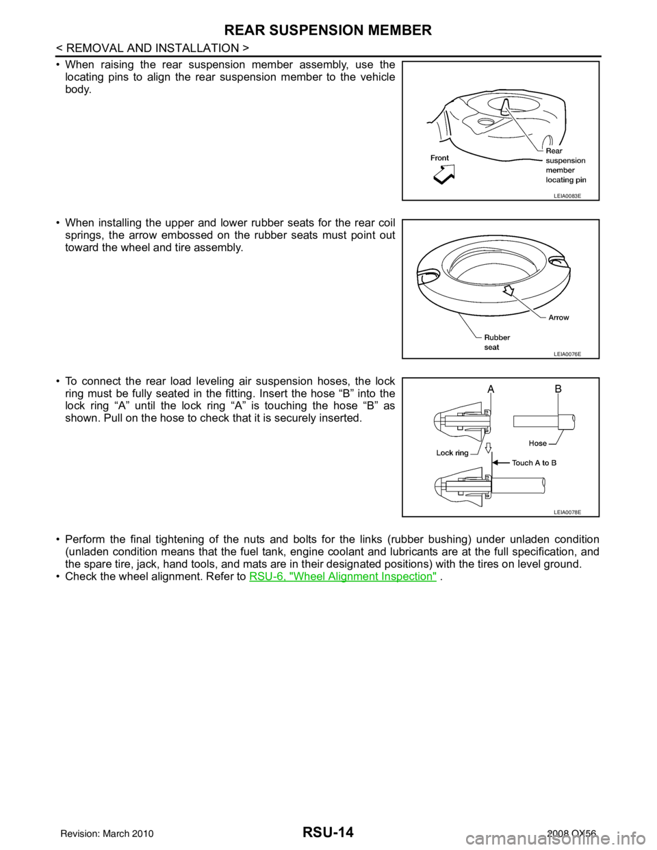
• When raising the rear suspension member assembly, use thelocating pins to align the rear suspension member to the vehicle
body.
• When installing the upper and lower rubber seats for the rear coil springs, the arrow embossed on the rubber seats must point out
toward the wheel and tire assembly.
• To connect the rear load leveling air suspension hoses, the lock ring must be fully seated in the fitt ing. Insert the hose “B” into the
lock ring “A” until the lock ring “A” is touching the hose “B” as
shown. Pull on the hose to check that it is securely inserted.
• Perform the final tightening of the nuts and bolts for the links (rubber bushing) under unladen condition (unladen condition means that the fuel tank, engine cool ant and lubricants are at the full specification, and
the spare tire, jack, hand tools, and mats are in t heir designated positions) with the tires on level ground.
• Check the wheel alignment. Refer to RSU-6, "
Wheel Alignment Inspection" .
LEIA0083E
LEIA0076E
LEIA0078E
Revision: March 2010 2008 QX56
Page 3060 of 4083
REAR LOWER LINK & COIL SPRINGRSU-21
< REMOVAL AND INSTALLATION >
C
DF
G H
I
J
K L
M A
B
RSU
N
O P
8. Slowly lower the suitable jack to release the coil spring tension. Then remove the upper rubber seat, coil spring, and lower rubber seat from the rear lower link.
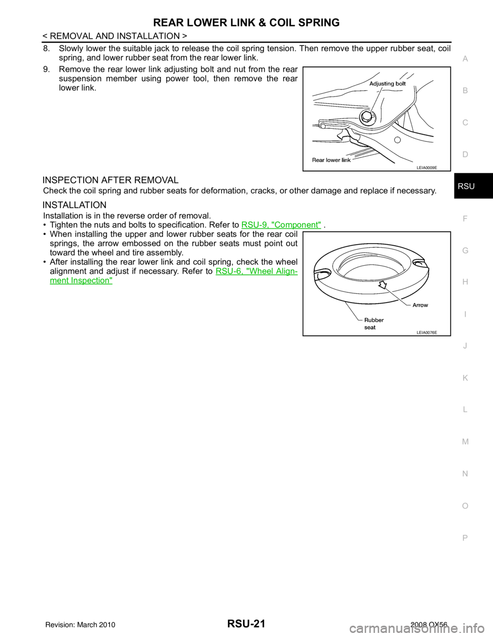
9. Remove the rear lower link adjusting bolt and nut from the rear suspension member using power tool, then remove the rear
lower link.
INSPECTION AFTER REMOVAL
Check the coil spring and rubber seats for deformation, cracks, or other damage and replace if necessary.
INSTALLATION
Installation is in the reverse order of removal.
• Tighten the nuts and bolts to specification. Refer to RSU-9, "
Component" .
• When installing the upper and lower rubber seats for the rear coil springs, the arrow embossed on the rubber seats must point out
toward the wheel and tire assembly.
• After installing the rear lower link and coil spring, check the wheel alignment and adjust if necessary. Refer to RSU-6, "
Wheel Align-
ment Inspection"
LEIA0009E
LEIA0076E
Revision: March 2010 2008 QX56
Page 3311 of 4083
![INFINITI QX56 2008 Factory Service Manual IPDM E/R (INTELLIGENT POWER DISTRIBUTION MODULE ENGINE ROOM)
SEC-103
< ECU DIAGNOSIS > [WITH INTELLIGENT KEY SYSTEM]
C
D
E
F
G H
I
J
L
M A
B
SEC
N
O P
41 Y/B Hood switch Input —Hood closed OFF
0V
Ho INFINITI QX56 2008 Factory Service Manual IPDM E/R (INTELLIGENT POWER DISTRIBUTION MODULE ENGINE ROOM)
SEC-103
< ECU DIAGNOSIS > [WITH INTELLIGENT KEY SYSTEM]
C
D
E
F
G H
I
J
L
M A
B
SEC
N
O P
41 Y/B Hood switch Input —Hood closed OFF
0V
Ho](/manual-img/42/57030/w960_57030-3310.png)
IPDM E/R (INTELLIGENT POWER DISTRIBUTION MODULE ENGINE ROOM)
SEC-103
< ECU DIAGNOSIS > [WITH INTELLIGENT KEY SYSTEM]
C
D
E
F
G H
I
J
L
M A
B
SEC
N
O P
41 Y/B Hood switch Input —Hood closed OFF
0V
Hood open ON Battery voltage
42 GR Oil pressure switch Input — Engine running
Battery voltage
Engine stopped 0V
43 L/Y Wiper auto stop signal Input ON or
START Wiper switch OFF, LO, INT Battery voltage
44 BR Daytime light relay
control Input ONDaytime light system active
0V
Daytime light system inactive Battery voltage
45 G/W Horn relay control Input ON When door locks are operated
using keyfob or Intelligent Key
(OFF
→ ON)* Battery voltage
→ 0V
46 GR Fuel pump relay con-
trol
Input —Ignition switch ON or START
0V
Ignition switch OFF or ACC Battery voltage
47 O Throttle control motor
relay control
Input —Ignition switch ON or START
0V
Ignition switch OFF or ACC Battery voltage
48 B/R Starter relay (trans-
mission range switch) Input
ON or
START A/T shift selector lever in "P"
or "N"
0V
A/T shift selector lever any
other position Battery voltage
49 R/L Trailer tow relay Output ON Lighting
switch must
be in the 1st
positionOFF
0V
ON Battery voltage
50 W/R Front fog lamp (LH) Output ON or
START Lighting
switch must
be in the 2nd
position
(LOW beam
is ON) and
the front fog
lamp switch OFF
0V
ON Battery voltage
51 W/R Front fog lamp (RH) Output ON or
START Lighting
switch must
be in the 2nd
position
(LOW beam
is ON) and
the front fog
lamp switch OFF
0V
ON Battery voltage
52 L LH low beam head-
lamp Output — Lighting switch in 2nd position Battery voltage
54 R/Y RH low beam head-
lamp
Output — Lighting switch in 2nd position Battery voltage
55 G LH high beam head-
lamp
Output —Lighting switch in 2nd position
and placed in HIGH or PASS
position
Battery voltage
56 L/W RH high beam head-
lamp Output —Lighting switch in 2nd position
and placed in HIGH or PASS
position Battery voltage
Te r m i n a l
Wire
col or Si
gn
al nameSignal
input/
output Measuring condition
Reference value(Approx.)
Igni-
tion
switch Operation or condition
Revision: March 2010
2008 QX56
Page 3319 of 4083
![INFINITI QX56 2008 Factory Service Manual INTELLIGENT KEY SYSTEM/ENGINE START FUNCTION SYMPTOMS
SEC-111
< SYMPTOM DIAGNOSIS > [WITH INTELLIGENT KEY SYSTEM]
C
D
E
F
G H
I
J
L
M A
B
SEC
N
O P
SYMPTOM DIAGNOSIS
INTELLIGENT KEY SYSTEM/ENGIN E STA INFINITI QX56 2008 Factory Service Manual INTELLIGENT KEY SYSTEM/ENGINE START FUNCTION SYMPTOMS
SEC-111
< SYMPTOM DIAGNOSIS > [WITH INTELLIGENT KEY SYSTEM]
C
D
E
F
G H
I
J
L
M A
B
SEC
N
O P
SYMPTOM DIAGNOSIS
INTELLIGENT KEY SYSTEM/ENGIN E STA](/manual-img/42/57030/w960_57030-3318.png)
INTELLIGENT KEY SYSTEM/ENGINE START FUNCTION SYMPTOMS
SEC-111
< SYMPTOM DIAGNOSIS > [WITH INTELLIGENT KEY SYSTEM]
C
D
E
F
G H
I
J
L
M A
B
SEC
N
O P
SYMPTOM DIAGNOSIS
INTELLIGENT KEY SYSTEM/ENGIN E START FUNCTION SYMPTOMS
Symptom TableINFOID:0000000001539175
NOTE:
• Before performing the diagnosis in the following table, check “ SEC-3, "
Work Flow"”.
• Check that vehicle is under the condition shown in “Conditions of vehicle” before starting diagnosis, and check each symptom.
• Engine cranking is enabled when the shift lever is in the "Park" position, and in the "Neutral" position only if the brake pedal is depressed.
• If the following symptoms are detec ted, check systems shown in the “Diagnosis/service procedure” column
in this order.
CONDITIONS OF VEHICLE (OPERATING CONDITIONS)
• Engine start function is ON when setting on CONSULT-III.
• Mechanical key is not inserted in key cylinder.
• One or more of Intelligent Keys with registered Intelligent Key ID is in the vehicle.
Symptom Diagnosis/service procedureReference
page
Ignition switch does not turn on with Intelligent Key.
[LCD displays "KEY DETECTED"] 1. Check steering lock solenoid.
DLK-95
2. Replace Intelligent Key unit.SEC-116
Ignition switch does not turn on with Intelligent Key.
[LCD does not display "PUSH" with arrow toward key
cylinder] 1. Check Intelligent Key unit power supply and ground circuit.
DLK-642. Check ignition knob switch.DLK-112
3. Check key switch (BCM input). D L K - 111
4. Check key switch (Intelligent Key unit input).DLK-109
5. Replace Intelligent Key unit.SEC-116
Ignition switch does not turn on with Intelligent Key.
[LCD displays " NO KEY"] 1a. Check inside key antenna 1 (rear of center console).
DLK-56
1b. Check inside key antenna 2 (luggage compartment).DLK-58
1c. Check inside key antenna 3 (front of center console).DLK-60
1d. Check inside key antenna 4 (overhead console area).DLK-64
2. Replace Intelligent Key unit.SEC-116
Ignition switch does not turn on with mechanical key1. Check key switch (BCM input).
D L K - 1112. Check key switch (Intelligent Key unit input).DLK-109
Engine cannot be cranked with transmission in "Park"
or in "Neutral" position with brake pedal depressed.1. Check transmission signal.
TM-43
2. Check stop lamp switch.EXL-81
Revision: March 2010 2008 QX56
Page 3378 of 4083
SR-2
< PRECAUTION >
PRECAUTIONS
PRECAUTION
PRECAUTIONS
Precaution for Supplemental Restraint System (SRS) "AIR BAG" and "SEAT BELT
PRE-TENSIONER"
INFOID:0000000004894350
The Supplemental Restraint System such as “A IR BAG” and “SEAT BELT PRE-TENSIONER”, used along
with a front seat belt, helps to reduce the risk or severity of injury to the driver and front passenger for certain
types of collision. This system includes seat belt switch inputs and dual stage front air bag modules. The SRS
system uses the seat belt switches to determine the front air bag deployment, and may only deploy one front
air bag, depending on the severity of a collision and w hether the front occupants are belted or unbelted.
Information necessary to service the system safely is included in the SR and SB section of this Service Man-
ual.
WARNING:
• To avoid rendering the SRS inopera tive, which could increase the risk of personal injury or death in
the event of a collision which would result in air bag inflation, all maintenance must be performed by
an authorized NISSAN/INFINITI dealer.
• Improper maintenance, including in correct removal and installation of the SRS, can lead to personal
injury caused by unintent ional activation of the system. For re moval of Spiral Cable and Air Bag
Module, see the SR section.
• Do not use electrical test equipmen t on any circuit related to the SRS unless instructed to in this
Service Manual. SRS wiring harn esses can be identified by yellow and/or orange harnesses or har-
ness connectors.
PRECAUTIONS WHEN USING POWER TOOLS (AIR OR ELECTRIC) AND HAMMERS
WARNING:
• When working near the Airbag Diagnosis Sensor Unit or other Airbag System sensors with the Igni-
tion ON or engine running, DO NOT use air or electri c power tools or strike near the sensor(s) with a
hammer. Heavy vibration could activate the sensor( s) and deploy the air bag(s), possibly causing
serious injury.
• When using air or electric power tools or hammers , always switch the Ignition OFF, disconnect the
battery, and wait at least 3 minu tes before performing any service.
Precaution for SRS "AIR BAG" and "S EAT BELT PRE-TENSIONER" Service
INFOID:0000000001602214
• Do not use electrical test equipment to check SRS ci rcuits unless instructed to in this Service Manual.
• Before servicing the SRS, turn ignition switch OFF, disconnect both battery terminals and wait at least 3 min- utes.
For approximately 3 minutes after the terminals are remov ed, it is still possible for the air bags and seat belt
pre-tensioners to deploy. Therefore, do not work on any SRS connectors or wires until at least 3 minutes
have passed.
• The air bag diagnosis sensor unit must always be installed with the arrow mark “ ⇐” pointing toward the front
of the vehicle for proper operation. Also check air bag diagnosis sensor unit for cracks, deformities or rust
before installation and replace as required.
• The spiral cable must be aligned with the neutral position since its rotations are limited. Do not attempt to
turn steering wheel or column after removal of steering gear.
• Handle air bag module carefully. Always place driver and front passenger air bag modules with the pad side facing upward and seat mounted front side air bag module standing with the stud bolt side facing down.
• Conduct self-diagnosis to check entire SRS for proper function after replacing any components.
• After air bag inflates, the front instrument panel assembly should be replaced if damaged.
Occupant Classification System PrecautionINFOID:0000000001602215
Replace control unit and passenger front seat cushion as an assembly.
Precaution Necessary for Steering Wheel Rotation After Battery Disconnect
INFOID:0000000004894349
NOTE:
Revision: March 2010 2008 QX56
Page 3384 of 4083
SR-8
< ON-VEHICLE REPAIR >
SPIRAL CABLE
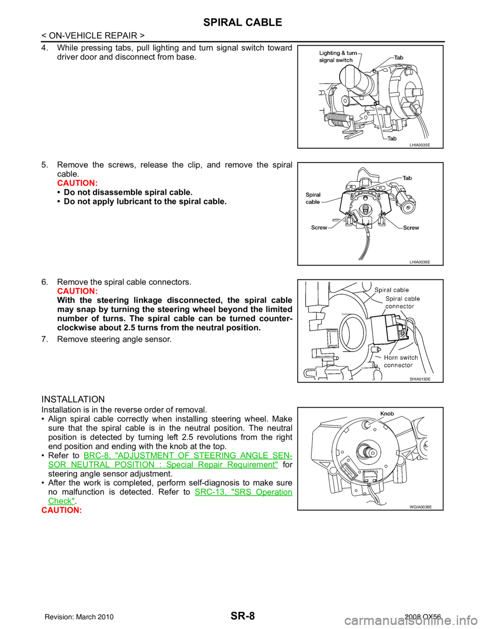
4. While pressing tabs, pull lighting and turn signal switch towarddriver door and disconnect from base.
5. Remove the screws, release the clip, and remove the spiral cable.
CAUTION:
• Do not disassemble spiral cable.
• Do not apply lubricant to the spiral cable.
6. Remove the spiral cable connectors. CAUTION:
With the steering linkage di sconnected, the spiral cable
may snap by turning the steer ing wheel beyond the limited
number of turns. The spiral cable can be turned counter-
clockwise about 2.5 turns fr om the neutral position.
7. Remove steering angle sensor.
INSTALLATION
Installation is in the reverse order of removal.
• Align spiral cable correctly when installing steering wheel. Make sure that the spiral cable is in the neutral position. The neutral
position is detected by turning left 2.5 revolutions from the right
end position and ending with the knob at the top.
• Refer to BRC-8, "
ADJUSTMENT OF STEERING ANGLE SEN-
SOR NEUTRAL POSITION : Special Repair Requirement" for
steering angle sensor adjustment.
• After the work is completed, perform self-diagnosis to make sure no malfunction is detected. Refer to SRC-13, "
SRS Operation
Check".
CAUTION:
LHIA0035E
LHIA0036E
SHIA0193E
WGIA0038E
Revision: March 2010 2008 QX56