2008 INFINITI QX56 tow
[x] Cancel search: towPage 2541 of 4083
![INFINITI QX56 2008 Factory Service Manual LAN-46
< FUNCTION DIAGNOSIS >[CAN]
CAN COMMUNICATION SYSTEM
NOTE:
CAN data of the air bag diagnosis sensor unit is not us
ed by usual service work, thus it is omitted.
Tire pressure data signal R T
T INFINITI QX56 2008 Factory Service Manual LAN-46
< FUNCTION DIAGNOSIS >[CAN]
CAN COMMUNICATION SYSTEM
NOTE:
CAN data of the air bag diagnosis sensor unit is not us
ed by usual service work, thus it is omitted.
Tire pressure data signal R T
T](/manual-img/42/57030/w960_57030-2540.png)
LAN-46
< FUNCTION DIAGNOSIS >[CAN]
CAN COMMUNICATION SYSTEM
NOTE:
CAN data of the air bag diagnosis sensor unit is not us
ed by usual service work, thus it is omitted.
Tire pressure data signal R T
Tire pressure signal R TR
Turn indicator signal TR
Buzzer output signal TR
Door lock/unlock request signal RT
Hazard request signal RT
Hazard warning lamp request signal RT
Ignition knob switch signal RT
KEY warning signal TR
LOCK warning signal TR
Panic alarm request signal RT
Power window open request signal RT
1st position switch signal R T
4th position switch signal R T
Distance to empty signal RT
Fuel level low warning signal RT
Fuel level sensor signal R T
Parking brake switch signal RT
Seat belt buckle switch signal RT
Stop lamp switch signal R T
Tow mode switch signal R T
Vehicle speed signal RRR RRR R T
RRRT
Steering angle sensor signal TR
ABS malfunction signal RT
ABS warning lamp signal RT
Brake pressure sensor signal RT
Brake warning lamp signal RT
SLIP indicator lamp signal RT
TCS malfunction signal RT
VDC malfunction signal RT
VDC OFF indicator lamp signal RRT
VDC operation signal RT
Front wiper stop position signal RT
High beam status signal R T
Hood switch signal RT
Low beam status signal R T
Rear window defogger control signal R RT
Ambient sensor signal RT
Signal name/Connecting unit
ECM
TCM
LASER ICC
ADP
AV
BCM
HVAC I-KEY M&A
STRG 4WDABS
IPDM-E
Revision: March 2010 2008 QX56
Page 2606 of 4083

MA-8
< ON-VEHICLE MAINTENANCE >
PERIODIC MAINTENANCE
PERIODIC MAINTENANCE
Introduction of Periodic MaintenanceINFOID:0000000001606164
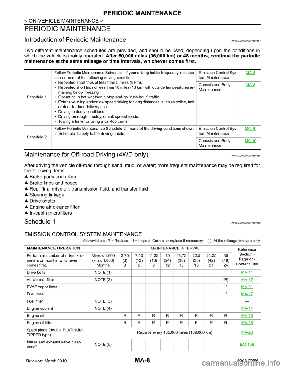
Two different maintenance schedules are provided, and should be used, depending upon the conditions in
which the vehicle is mainly operated. After 60,000 miles (96,000 km) or 48 months, continue the periodic
maintenance at the same mileage or ti me intervals, whichever comes first.
Maintenance for Off-road Driving (4WD only)INFOID:0000000001606165
After driving the vehicle off-road through sand, mud, or water; more frequent maintenance may be required for
the following items:
Brake pads and rotors
Brake lines and hoses
Rear final drive oil, transmission fluid, and transfer fluid
Steering linkage
Drive shafts
Engine air cleaner filter
In-cabin microfilters
Schedule 1INFOID:0000000001606166
EMISSION CONTROL SYSTEM MAINTENANCE
Abbreviations: R = Replace. I = Inspect. Correct or r eplace if necessary. [ ]: At the mileage intervals only
Schedule 1Follow Periodic Maintenance Schedule 1 if your driving habits frequently includes
one or more of the following driving conditions:
• Repeated short trips of less than 5 miles (8 km).
• Repeated short trips of less than 10 miles (16 km) with outside temperatures re-
maining below freezing.
• Operating in hot weather in stop-and-go “rush hour” traffic.
• Extensive idling and/or low speed driving for long distances, such as police, taxi
or door-to-door delivery use.
• Driving in dusty conditions.
• Driving on rough, muddy, or salt spread roads.
• Towing a trailer or using a car-top carrier. Emission Control Sys-
tem Maintenance
MA-8
Chassis and Body
Maintenance
MA-8
Schedule 2Follow Periodic Maintenance Schedule 2 if none of the driving conditions shown
in Schedule 1 apply to the driving habits.
Emission Control Sys-
tem MaintenanceMA-10Chassis and Body
Maintenance
MA-10
MAINTENANCE OPERATION
MAINTENANCE INTERVAL
Reference
Section -
Page or -
Content Title
Perform at number of miles, kilo-
meters or months, whichever
comes first. Miles x 1,000
(km x 1,000) Months 3.75
(6)3 7.50
(12) 6 11 . 2 5
(18) 9 15
(24) 12 18.75
(30)15 22.5
(36) 18 26.25
(42)21 30
(48) 24
Drive belts NOTE (1) MA-14
Air cleaner filterNOTE (2) [R]MA-17
EVAP vapor lines I*MA-21
Fuel lines I*MA-17
Fuel filter NOTE (3) —
Engine coolant NOTE (4) MA-14
Engine oilR R R R R R R R MA-18
Engine oil filterR R R R R R R R MA-18
Spark plugs (double PLATINUM-
TIPPED type)Replace every 105,000 miles (169,000 km).
MA-20
Intake and exhaust valve clear-
ance*NOTE (5)
EM-108
Revision: March 2010 2008 QX56
Page 2608 of 4083

MA-10
< ON-VEHICLE MAINTENANCE >
PERIODIC MAINTENANCE
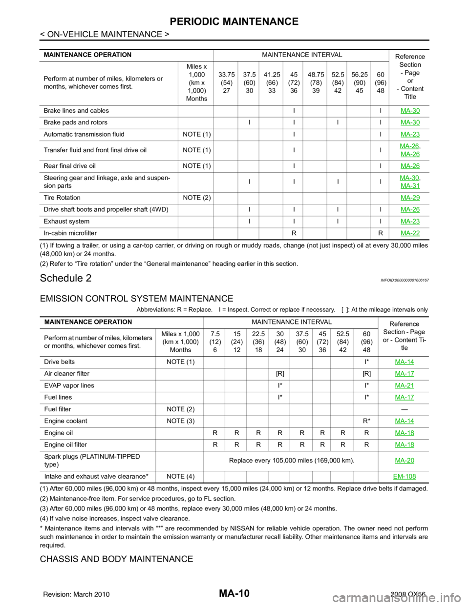
(1) If towing a trailer, or using a car-top carrier, or driving on rough or muddy roads, change (not just inspect) oil at every 30,000 miles
(48,000 km) or 24 months.
(2) Refer to “Tire rotation” unde r the “General maintenance” heading earlier in this section.
Schedule 2INFOID:0000000001606167
EMISSION CONTROL SYSTEM MAINTENANCE
Abbreviations: R = Replace. I = Inspect. Correct or r eplace if necessary. [ ]: At the mileage intervals only
(1) After 60,000 miles (96,000 km) or 48 months, inspect every 15,000 miles (24,000 km) or 12 months. Replace drive belts if damaged.
(2) Maintenance-free item. For service procedures, go to FL section.
(3) After 60,000 miles (96,000 km) or 48 months, replace every 30,000 miles (48,000 km) or 24 months.
(4) If valve noise increases, inspect valve clearance.
* Maintenance items and intervals with “*” are recommended by NISSAN for reliable vehicle operation. The owner need not perform
such maintenance in order to maintain the emission warranty or manufacturer recall liability. Other maintenance items and inter vals are
required.
CHASSIS AND BODY MAINTENANCE
MAINTENANCE OPERATION MAINTENANCE INTERVAL
Reference
Section
- Page or
- Content
Title
Perform at number of miles, kilometers or
months, whichever comes first. Miles x
1,000(km x
1,000)
Months 33.75
(54)
27 37.5
(60)
30 41.25
(66)
33 45
(72)
36 48.75
(78)
39 52.5
(84)
42 56.25
(90)
45 60
(96)
48
Brake lines and cables IIMA-30
Brake pads and rotors IIIIMA-30
Automatic transmission fluid NOTE (1)IIMA-23
Transfer fluid and front final drive oil NOTE (1)IIMA-26,
MA-26
Rear final drive oil NOTE (1)IIMA-26
Steering gear and linkage, axle and suspen-
sion parts IIIIMA-30,
MA-31
Tire Rotation NOTE (2) MA-29
Drive shaft boots and propeller shaft (4WD)IIIIMA-26
Exhaust system IIIIMA-23
In-cabin microfilter RRMA-22
MAINTENANCE OPERATION MAINTENANCE INTERVAL
Reference
Section - Page
or - Content Ti- tle
Perform at number of miles, kilometers
or months, whichever comes first. Miles x 1,000
(km x 1,000)
Months 7.5
(12)
6 15
(24)
12 22.5
(36)
18 30
(48)
24 37.5
(60)
30 45
(72)
36 52.5
(84)
42 60
(96)
48
Drive belts NOTE (1) I*MA-14
Air cleaner filter [R][R]MA-17
EVAP vapor lines I*I*MA-21
Fuel lines I*I*MA-17
Fuel filter NOTE (2) —
Engine coolant NOTE (3) R*MA-14
Engine oil R R R R R R R R MA-18
Engine oil filterR R R R R R R R MA-18
Spark plugs (PLATINUM-TIPPED
type) Replace every 105,000 miles (169,000 km).
MA-20
Intake and exhaust valve clearance* NOTE (4) EM-108
Revision: March 20102008 QX56
Page 2644 of 4083

MIR-12
< REMOVAL AND INSTALLATION >
DOOR MIRROR
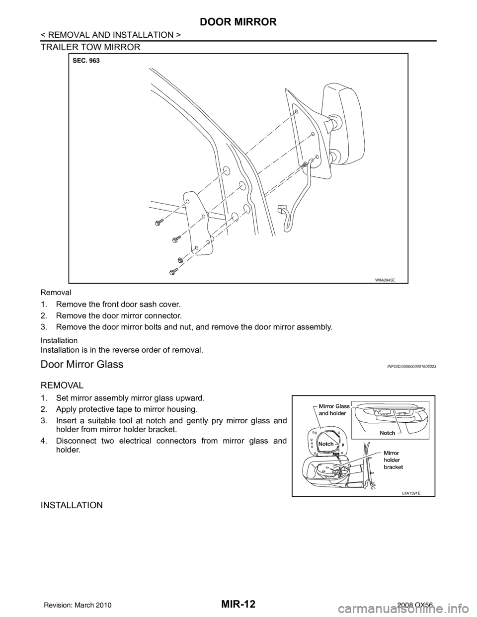
TRAILER TOW MIRROR
Removal
1. Remove the front door sash cover.
2. Remove the door mirror connector.
3. Remove the door mirror bolts and nut, and remove the door mirror assembly.
Installation
Installation is in the reverse order of removal.
Door Mirror GlassINFOID:0000000001608223
REMOVAL
1. Set mirror assembly mirror glass upward.
2. Apply protective tape to mirror housing.
3. Insert a suitable tool at notch and gently pry mirror glass and
holder from mirror holder bracket.
4. Disconnect two electrical connectors from mirror glass and holder.
INSTALLATION
WIIA0945E
LIIA1591E
Revision: March 2010 2008 QX56
Page 2712 of 4083

MWI
THE FUEL GAUGE POINTER DOES NOT MOVE TO "F" WHEN REFUELING
MWI-67
< SYMPTOM DIAGNOSIS >
C
D E
F
G H
I
J
K L
M B A
O P
THE FUEL GAUGE POINTER DOES NOT MOVE TO "F" WHEN REFUEL-
ING
DescriptionINFOID:0000000001691327
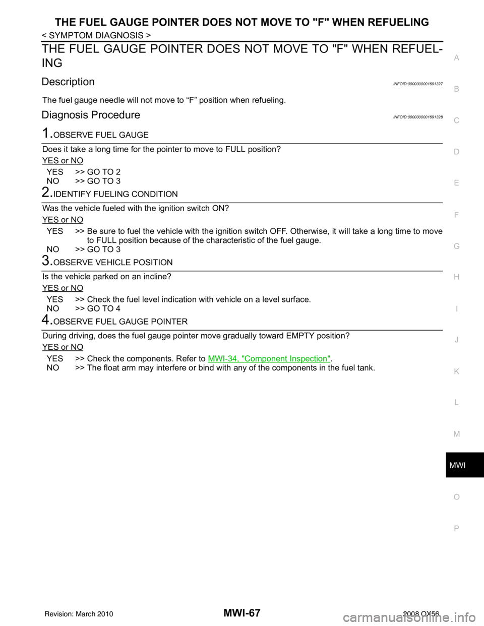
The fuel gauge needle will not move to “F” position when refueling.
Diagnosis ProcedureINFOID:0000000001691328
1.OBSERVE FUEL GAUGE
Does it take a long time for the pointer to move to FULL position?
YES or NO
YES >> GO TO 2
NO >> GO TO 3
2.IDENTIFY FUELING CONDITION
Was the vehicle fueled with the ignition switch ON?
YES or NO
YES >> Be sure to fuel the vehicle with the ignition swit ch OFF. Otherwise, it will take a long time to move
to FULL position because of the c haracteristic of the fuel gauge.
NO >> GO TO 3
3.OBSERVE VEHICLE POSITION
Is the vehicle parked on an incline?
YES or NO
YES >> Check the fuel level indicati on with vehicle on a level surface.
NO >> GO TO 4
4.OBSERVE FUEL GAUGE POINTER
During driving, does the fuel gauge pointer move gradually toward EMPTY position?
YES or NO
YES >> Check the components. Refer to MWI-34, "Component Inspection".
NO >> The float arm may interfere or bind with any of the components in the fuel tank.
Revision: March 2010 2008 QX56
Page 2739 of 4083
![INFINITI QX56 2008 Factory Service Manual PCS-6
< FUNCTION DIAGNOSIS >[IPDM E/R]
RELAY CONTROL SYSTEM
System Description
INFOID:0000000001696481
IPDM E/R activates the internal cont rol circuit to perform the relay ON-OFF control according to INFINITI QX56 2008 Factory Service Manual PCS-6
< FUNCTION DIAGNOSIS >[IPDM E/R]
RELAY CONTROL SYSTEM
System Description
INFOID:0000000001696481
IPDM E/R activates the internal cont rol circuit to perform the relay ON-OFF control according to](/manual-img/42/57030/w960_57030-2738.png)
PCS-6
< FUNCTION DIAGNOSIS >[IPDM E/R]
RELAY CONTROL SYSTEM
System Description
INFOID:0000000001696481
IPDM E/R activates the internal cont rol circuit to perform the relay ON-OFF control according to the input sig-
nals from various sensors and the request signals received from control units via CAN communication.
CAUTION:
IPDM E/R integrated relays cannot be removed.
Control relay Input/outputTransmit unitControl partReference
page
Front fog lamp relay Front fog lamp request signal BCM (CAN) Front fog lampsEXL-15
• Headlamp high relay
• Headlamp low relay • High beam request signal
• Low beam request signal
BCM (CAN)• Headlamp high
• Headlamp lowEXL-7
EXL-7
Tail lamp relay
Position light request signal BCM (CAN) •Parking lamps
• License plate lamps
• Tail lamps
• Trailer tow relay
• Illumination systemEXL-18
• Front wiper relay
• Front wiper high relay
Front wiper request signal BCM (CAN)
Front wiper motorWW-4
Rear window defogger re-
lay Rear window defogger re-
quest signal
BCM (CAN)
Rear window defoggerWW-8
A/C relay A/C request signal •BCM (CAN)
•ECM (CAN)
A/C compressor
HAC-20
Starter relay Ignition switch START signal TCM Starter motorSTR-8
Cooling fan relay Cooling fan request signal ECM (CAN) Cooling fan relayEC-36
Heated mirror relay Heate d mirror request signal BCM (CAN) Door mirrors DEF-4
ECM relayECM relay control signal ECM (CAN) ECM relayEC-21
Throttle control motor relay Throttle control motor control
signal ECM (CAN)
Throttle contro
l motor re-
lay EC-28
Fuel pump relay
Fuel pump request signal ECM (CAN) Fuel pumpEC-28
Ignition relay Ignition switch ON signal Ignition switch Ignition relayEC-31
Revision: March 2010 2008 QX56
Page 2757 of 4083
![INFINITI QX56 2008 Factory Service Manual PCS-24
< ECU DIAGNOSIS >[IPDM E/R]
IPDM E/R (INTELLIGENT POWER DI
STRIBUTION MODULE ENGINE ROOM)
41 Y/B Hood switch Input —Hood closed OFF
0V
Hood open ON Battery voltage
42 GR Oil pressure switch I INFINITI QX56 2008 Factory Service Manual PCS-24
< ECU DIAGNOSIS >[IPDM E/R]
IPDM E/R (INTELLIGENT POWER DI
STRIBUTION MODULE ENGINE ROOM)
41 Y/B Hood switch Input —Hood closed OFF
0V
Hood open ON Battery voltage
42 GR Oil pressure switch I](/manual-img/42/57030/w960_57030-2756.png)
PCS-24
< ECU DIAGNOSIS >[IPDM E/R]
IPDM E/R (INTELLIGENT POWER DI
STRIBUTION MODULE ENGINE ROOM)
41 Y/B Hood switch Input —Hood closed OFF
0V
Hood open ON Battery voltage
42 GR Oil pressure switch Input — Engine running
Battery voltage
Engine stopped 0V
43 L/Y Wiper auto stop signal Input ON or
START Wiper switch OFF, LO, INT Battery voltage
44 BR Daytime light relay
control Input ONDaytime light system active
0V
Daytime light system inactive Battery voltage
45 G/W Horn relay control Input ON When door locks are operated
using keyfob or Intelligent Key
(OFF
→ ON)* Battery voltage
→ 0V
46 GR Fuel pump relay con-
trol
Input —Ignition switch ON or START
0V
Ignition switch OFF or ACC Battery voltage
47 O Throttle control motor
relay control
Input —Ignition switch ON or START
0V
Ignition switch OFF or ACC Battery voltage
48 B/R Starter relay (trans-
mission range switch) Input
ON or
START A/T shift selector lever in "P"
or "N"
0V
A/T shift selector lever any
other position Battery voltage
49 R/L Trailer tow relay Output ON Lighting
switch must
be in the 1st
positionOFF
0V
ON Battery voltage
50 W/R Front fog lamp (LH) Output ON or
START Lighting
switch must
be in the 2nd
position
(LOW beam
is ON) and
the front fog
lamp switch OFF
0V
ON Battery voltage
51 W/R Front fog lamp (RH) Output ON or
START Lighting
switch must
be in the 2nd
position
(LOW beam
is ON) and
the front fog
lamp switch OFF
0V
ON Battery voltage
52 L LH low beam head-
lamp Output — Lighting switch in 2nd position Battery voltage
54 R/Y RH low beam head-
lamp
Output — Lighting switch in 2nd position Battery voltage
55 G LH high beam head-
lamp
Output —Lighting switch in 2nd position
and placed in HIGH or PASS
position
Battery voltage
56 L/W RH high beam head-
lamp Output —Lighting switch in 2nd position
and placed in HIGH or PASS
position Battery voltage
Te r m i n a l
Wire
co lor Si
gn
al nameSignal
input/
output Measuring condition
Reference value(Approx.)
Igni-
tion
switch Operation or condition
Revision: March 2010
2008 QX56
Page 2809 of 4083

PG-42
< COMPONENT DIAGNOSIS >
HARNESS
A3 M6 W/10 : To E10A2 M92 B/6 : Power liftgate switch
A2 M7 B/5 : Passenger select unlock relay D1 M93 W/24 : Display unit
A3 M8 W/16 : To D2 A2 M95 W/6 : Rear power vent window switch
A2 M9 BR/24 : To D1 A2 M96 BR/6 : Pedal adjusting switch
A3 M10 Y/4 : To E29 C2 M98 W/16 : A/C and AV switch assembly
A3 M11 B/1 : Parking brake switch C3 M99 BR/2 : Foot lamp LH
C3 M12 GR/6 : Key switch and ignition knob switch F4 M100 BR/2 : Foot lamp RH
D3 M13 BR/2 : Front passenger air bag OFF indicator F4 M101 Y/2 : Driver air bag module
B3 M15 W/4 : Steering lock solenoid F4 M102 GR/8 : Combination switch (spiral cable)
A2 M16 GR/6 : ADP steering switch F4 M103 Y/2 : Driver air bag module
B2 M17 W/8 : Steering angle sensor E3 M104 W/4 : Aux jack
C2 M18 W/40 : BCM (body control module) F2 M105 Y/2 : Front passenger air bag module
C2 M19 W/15 : BCM (body control module) F2 M106 O/2 : Front passenger air bag module
C2 M20 B/15 : BCM (body control module) F3 M107 B/5 : Front blower relay
C3 M22 W/16 : Data link connector D5 M108 B/6 : Yaw rate/ side/ decel G sensor
B1 M23 W/12 : Combination meter A1 M109 BR/2 : Front tweeter LH
C1 M24 W/40 : Combination meter D2 M110 BR/2 : Center speaker
F2 M25 B/4 : Remote keyless entry receiver F2 M111 BR/2 : Front tweeter LH
B2 M26 W/6 : Ignition switch C2M112 BR/14 : BO SE speaker amp.
A2 M27 B/2 : Diode-3 C2 M113 BR/23 : BOSE speaker amp.
B2 M28 W/16 : Combination switch B3 M114 W/2 : Heated steering wheel
B2 M29 Y/6 : Combination switch (spiral cable) A2 M116 GR/8 : Sonar system OFF switch
B3 M30 GR/8 : Combination switch (spiral cable) B1 M118 BR/2 : Front sonar buzzer
G4 M31 SMJ : To E152 F2 M120 W/4 : Remote keyless entry receiver
C3 M32 W/4 : In-vehicle sensor F4 M122 W/4 : Variable blower control (front)
B3 M33 W/32 : Automatic drive position control unit C3 M123 W/2 : Tire pressure warning check connector
B3 M34 W/16 : Automatic drive position control unit D2 M124 GR/3 : AV control unit
C5 M35 Y/28 : Air bag diagnosis sensor unit D2 M125 B/1 : Satellite radio antenna
G4 M36 SMJ : To B149 C3 M129 V/1 : Satellite radio tuner
G3 M37 B/1 : Fuse block (J/B) D2 M139 B/2 : Diode-1
G3 M38 B/2 : Fuse block (J/B) D1 M140 B/2 : Diode-2
D3 M39 W/8 : Fuse block (J/B) C2 M141 GR/8 : 4WD shift switch
A3 M40 SMJ : To B69 E1 M142 B/6 : Mode door motor (front)
D2 M42 W/20 : AV control unit E3 M143 B/6 : Air mix door motor (passenger)
D2 M43 W/12 : AV control unit C1 M144 B/6 : Defroster door motor
D2 M44 W/32 : AV control unit E3 M146 GR/2 : Intake sensor
D3 M45 W/40 : AV control unit D3 M147B/6 : Air mix doo r motor (driver)
D2 M46 W/32 : AV control unit D2 M148 W/4 : Headlamp aiming switch
D2 M49 L/26 : A/C auto AMP D3 M149 W/4 : Clock
D2 M50 B/26 : A/C auto AMP B1 M150 W/2 : Ignition keyhole illumination
B3 M51 L/4 : Trailer tow relay 1 G4 M157 W/20 : To B161
B2 M52 W/2 : Combination switch (spiral cable) A3 M158 W/10 : To D3
D3 M53 B/3 : Front power socket LH Console sub-harness
E3 M54 B/3 : Front power socket RH (for cigarette
lighter) D4 M201 W/16 : To M56
D2 M55 W/4 : Hazard switch D4 M202 BR/24 : To M64
Revision: March 2010 2008 QX56