2008 INFINITI QX56 tow
[x] Cancel search: towPage 3725 of 4083
TM-178
< ON-VEHICLE MAINTENANCE >
A/T FLUID
ON-VEHICLE MAINTENANCE
A/T FLUID
Checking the A/T Fluid (ATF)INFOID:0000000004917424
CAUTION:
If using the vehicle for towing, the A/T fluid must be replaced as specified. Refer to MA-8, "
Introduc-
tion of Periodic Maintenance".
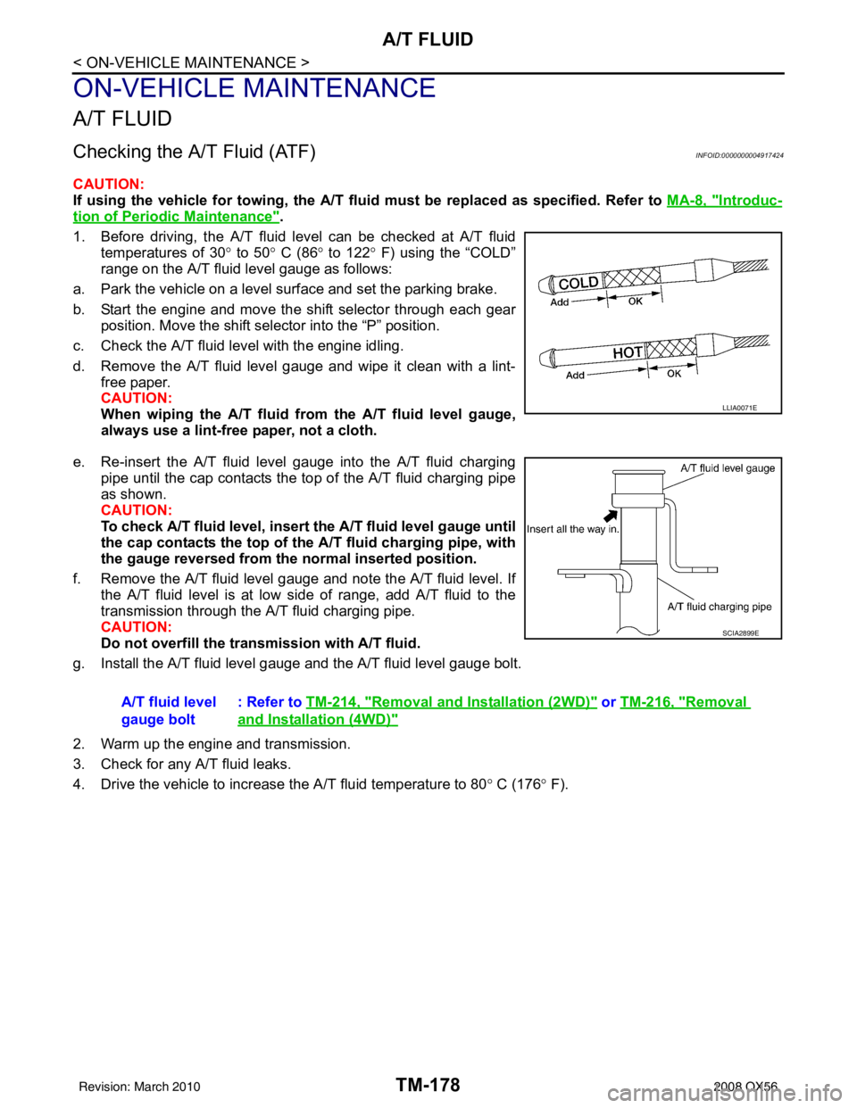
1. Before driving, the A/T fluid level can be checked at A/T fluid temperatures of 30 ° to 50° C (86° to 122° F) using the “COLD”
range on the A/T fluid level gauge as follows:
a. Park the vehicle on a level surface and set the parking brake.
b. Start the engine and move the shift selector through each gear position. Move the shift selector into the “P” position.
c. Check the A/T fluid level with the engine idling.
d. Remove the A/T fluid level gauge and wipe it clean with a lint- free paper.
CAUTION:
When wiping the A/T fluid from the A/ T fluid level gauge,
always use a lint-free paper, not a cloth.
e. Re-insert the A/T fluid level gauge into the A/T fluid charging pipe until the cap contacts the t op of the A/T fluid charging pipe
as shown.
CAUTION:
To check A/T fluid level, insert th e A/T fluid level gauge until
the cap contacts the top of the A/T fluid charging pipe, with
the gauge reversed from th e normal inserted position.
f. Remove the A/T fluid level gauge and note the A/T fluid level. If the A/T fluid level is at low si de of range, add A/T fluid to the
transmission through the A/T fluid charging pipe.
CAUTION:
Do not overfill the transmission with A/T fluid.
g. Install the A/T fluid level gauge and the A/T fluid level gauge bolt.
2. Warm up the engine and transmission.
3. Check for any A/T fluid leaks.
4. Drive the vehicle to increase the A/T fluid temperature to 80 ° C (176 ° F).
LLIA0071E
A/T fluid level
gauge bolt : Refer to
TM-214, "Removal and Installation (2WD)" or TM-216, "Removal
and Installation (4WD)"
SCIA2899E
Revision: March 2010 2008 QX56
Page 3727 of 4083
TM-180
< ON-VEHICLE MAINTENANCE >
A/T FLUID
Changing the A/T Fluid (ATF)
INFOID:0000000004917425
CAUTION:
If using the vehicle for towing, the A/T fl uid must be replaced as specified. Refer to MA-8, "
Introduc-
tion of Periodic Maintenance".
1. Drive the vehicle to warm up the A/T fluid to approximately 80 ° C (176 ° F).
2. Stop the engine.
3. Remove the A/T fluid level gauge.
4. Drain the A/T fluid from the drain plug hole, then install the drain plug with a new gasket. Refill the transmission with new A/T
fluid. Always refill with the same volume as the drained A/T fluid.
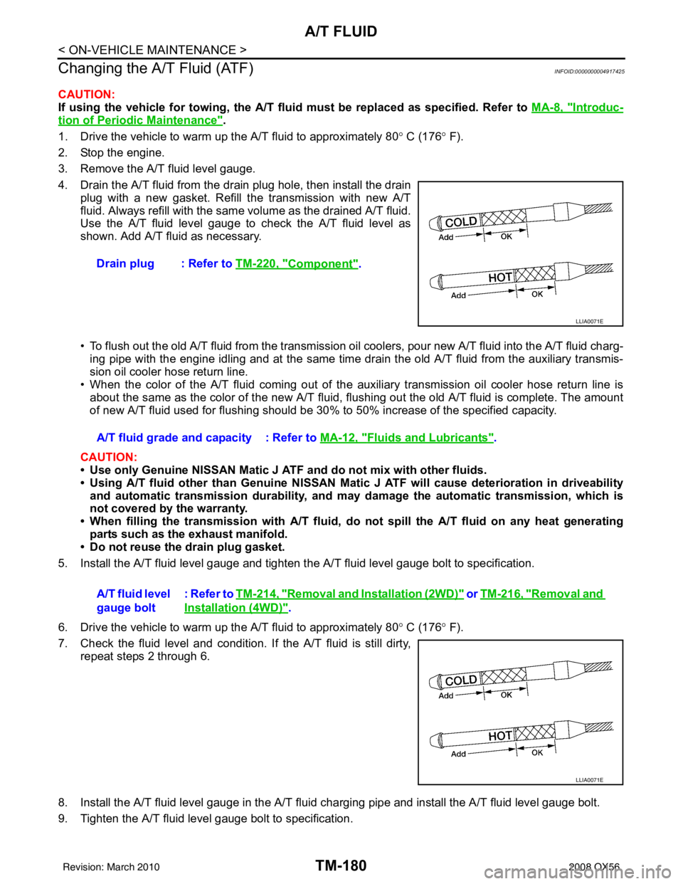
Use the A/T fluid level gauge to check the A/T fluid level as
shown. Add A/T fluid as necessary.
• To flush out the old A/T fluid from the transmission oil coolers, pour new A/T fluid into the A/T fluid charg-
ing pipe with the engine idling and at the same time drain the old A/T fluid from the auxiliary transmis-
sion oil cooler hose return line.
• When the color of the A/T fluid coming out of the auxiliary transmission oil cooler hose return line is
about the same as the color of the new A/T fluid, flushing out the old A/T fluid is complete. The amount
of new A/T fluid used for flushing should be 30% to 50% increase of the specified capacity.
CAUTION:
• Use only Genuine NISSAN Matic J ATF and do not mix with other fluids.
• Using A/T fluid other than Genuine NISSAN Mati c J ATF will cause deterioration in driveability
and automatic transmission durability, and may damage the automatic transmission, which is
not covered by the warranty.
• When filling the transmission with A/T fluid, do not spill the A/T fluid on any heat generating parts such as the exhaust manifold.
• Do not reuse the drain plug gasket.
5. Install the A/T fluid level gauge and tighten the A/T fluid level gauge bolt to specification.
6. Drive the vehicle to warm up the A/T fluid to approximately 80 ° C (176 ° F).
7. Check the fluid level and condition. If the A/T fluid is still dirty, repeat steps 2 through 6.
8. Install the A/T fluid level gauge in the A/T fluid charging pipe and install the A/T fluid level gauge bolt.
9. Tighten the A/T fluid level gauge bolt to specification. Drain plug : Refer to
TM-220, "
Component".
LLIA0071E
A/T fluid grade and capacity : Refer to MA-12, "Fluids and Lubricants".
A/T fluid level
gauge bolt : Refer to TM-214, "
Removal and Installation (2WD)" or TM-216, "Removal and
Installation (4WD)".
LLIA0071E
Revision: March 2010
2008 QX56
Page 3730 of 4083
A/T FLUID COOLERTM-183
< ON-VEHICLE MAINTENANCE >
CEF
G H
I
J
K L
M A
B
TM
N
O P
13. Flush each steel line from the cooler side back toward the A/T by spraying Transmission Cooler Cleaner in a continuous stream for 5 seconds.
14. Blow compressed air regulated to 490 - 883 kPa (5 - 9 kg/cm
2 ,71 - 128 psi) through each steel line from
the cooler side back toward the A/T for 10 seconds to force out any remaining fluid.
15. Ensure all debris is removed from the steel cooler lines.
16. Ensure all debris is removed from the banjo bolts and fittings.
17. Perform A/T fluid cooler diagnosis procedure.
A/T FLUID COOLER DIAGNOSIS PROCEDURE
NOTE:
Insufficient cleaning of the cooler inlet hose exte rior may lead to inaccurate debris identification.
1. Position a drain pan under the A/T inlet and outlet fluid cooler tube to cooler hose connection.
2. Clean the exterior and tip of the cooler inlet hose.
3. Put a different color matching mark on each cooler tube to cooler hose connection to aid in assembly. CAUTION:
Use paint to make the matching mark. Do not damage the tubes or hose.
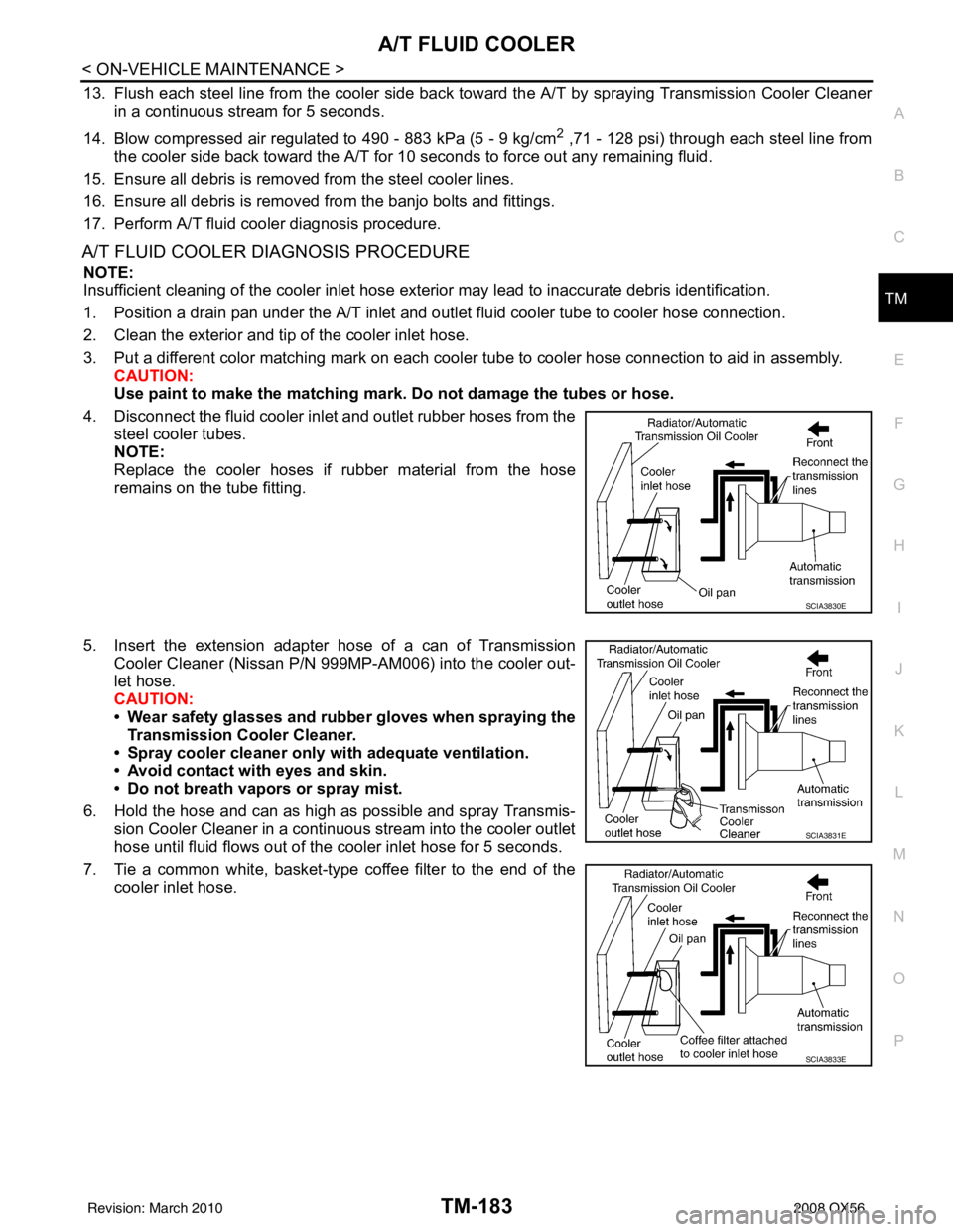
4. Disconnect the fluid cooler inle t and outlet rubber hoses from the
steel cooler tubes.
NOTE:
Replace the cooler hoses if rubber material from the hose
remains on the tube fitting.
5. Insert the extension adapter hose of a can of Transmission Cooler Cleaner (Nissan P/N 999MP-AM006) into the cooler out-
let hose.
CAUTION:
• Wear safety glasses and rubber gloves when spraying the
Transmission Cooler Cleaner.
• Spray cooler cleaner only with adequate ventilation.
• Avoid contact with eyes and skin.
• Do not breath vapors or spray mist.
6. Hold the hose and can as high as possible and spray Transmis- sion Cooler Cleaner in a continuous stream into the cooler outlet
hose until fluid flows out of the cooler inlet hose for 5 seconds.
7. Tie a common white, basket-type coffee filter to the end of the cooler inlet hose.
SCIA3830E
SCIA3831E
SCIA3833E
Revision: March 2010 2008 QX56
Page 3754 of 4083
CONTROL VALVE WITH TCMTM-207
< ON-VEHICLE REPAIR >
CEF
G H
I
J
K L
M A
B
TM
N
O P
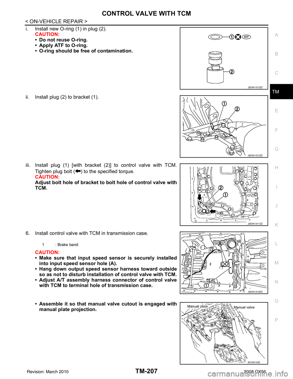
i. Install new O-ring (1) in plug (2). CAUTION:
• Do not reuse O-ring.
• Apply ATF to O-ring.
• O-ring should be free of contamination.
ii. Install plug (2) to bracket (1).
iii. Install plug (1) [with bracket (2)] to control valve with TCM. Tighten plug bolt ( ) to the specified torque.
CAUTION:
Adjust bolt hole of bracket to bolt hole of control valve with
TCM.
6. Install control valve with TCM in transmission case. CAUTION:
• Make sure that input speed sensor is securely installed
into input speed sensor hole (A).
• Hang down output speed sensor harness toward outside
so as not to disturb installati on of control valve with TCM.
• Adjust A/T assembly harness connector of control valve with TCM to terminal hole of transmission case.
• Assemble it so that manual valve cutout is engaged with
manual plate projection.
JSDIA1313ZZ
JSDIA1312ZZ
JSDIA1311ZZ
1 : Brake band
JSDIA1318ZZ
SCIA5142E
Revision: March 2010 2008 QX56
Page 3834 of 4083
ASSEMBLYTM-287
< DISASSEMBLY AND ASSEMBLY >
CEF
G H
I
J
K L
M A
B
TM
N
O P
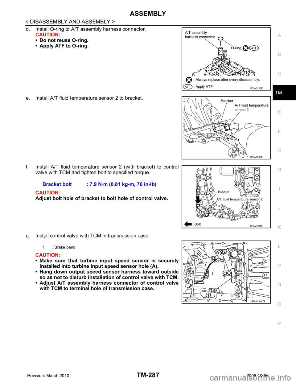
d. Install O-ring to A/T assembly harness connector. CAUTION:
• Do not reuse O-ring.
• Apply ATF to O-ring.
e. Install A/T fluid temperature sensor 2 to bracket.
f. Install A/T fluid temperature sensor 2 (with bracket) to control valve with TCM and tighten bolt to specified torque.
CAUTION:
Adjust bolt hole of bracket to bolt hole of control valve.
g. Install control valve with TCM in transmission case. CAUTION:
• Make sure that turbine input speed sensor is securelyinstalled into turbine input speed sensor hole (A).
• Hang down output speed sensor harness toward outside
so as not to disturb installati on of control valve with TCM.
• Adjust A/T assembly harness connector of control valve with TCM to terminal hole of transmission case.
SCIA5155E
SCIA5264E
Bracket bolt : 7.9 N·m (0.81 kg-m, 70 in-lb)
SCIA5301E
1 : Brake band
JSDIA1318ZZ
Revision: March 2010 2008 QX56
Page 4057 of 4083

WW-60
< ECU DIAGNOSIS >
IPDM E/R (INTELLIGENT POWER DISTRIBUTION MODULE ENGINE ROOM)
41 Y/B Hood switch Input —Hood closed OFF
0V
Hood open ON Battery voltage
42 GR Oil pressure switch Input — Engine running
Battery voltage
Engine stopped 0V
43 L/Y Wiper auto stop signal Input ON or
START Wiper switch OFF, LO, INT Battery voltage
44 BR Daytime light relay
control Input ONDaytime light system active
0V
Daytime light system inactive Battery voltage
45 G/W Horn relay control Input ON When door locks are operated
using keyfob or Intelligent Key
(OFF
→ ON)* Battery voltage
→ 0V
46 GR Fuel pump relay con-
trol
Input —Ignition switch ON or START
0V
Ignition switch OFF or ACC Battery voltage
47 O Throttle control motor
relay control
Input —Ignition switch ON or START
0V
Ignition switch OFF or ACC Battery voltage
48 B/R Starter relay (trans-
mission range switch) Input
ON or
START A/T shift selector lever in "P"
or "N"
0V
A/T shift selector lever any
other position Battery voltage
49 R/L Trailer tow relay Output ON Lighting
switch must
be in the 1st
positionOFF
0V
ON Battery voltage
50 W/R Front fog lamp (LH) Output ON or
START Lighting
switch must
be in the 2nd
position
(LOW beam
is ON) and
the front fog
lamp switch OFF
0V
ON Battery voltage
51 W/R Front fog lamp (RH) Output ON or
START Lighting
switch must
be in the 2nd
position
(LOW beam
is ON) and
the front fog
lamp switch OFF
0V
ON Battery voltage
52 L LH low beam head-
lamp Output — Lighting switch in 2nd position Battery voltage
54 R/Y RH low beam head-
lamp
Output — Lighting switch in 2nd position Battery voltage
55 G LH high beam head-
lamp
Output —Lighting switch in 2nd position
and placed in HIGH or PASS
position
Battery voltage
56 L/W RH high beam head-
lamp Output —Lighting switch in 2nd position
and placed in HIGH or PASS
position Battery voltage
Te r m i n a l
Wire
co lor Si
gn
al nameSignal
input/
output Measuring condition
Reference value(Approx.)
Igni-
tion
switch Operation or condition
Revision: March 2010
2008 QX56
Page 4082 of 4083
REAR WIPER AND WASHER SYSTEMWW-85
< ON-VEHICLE REPAIR >
C
DE
F
G H
I
J
K
M A
B
WW
N
O P
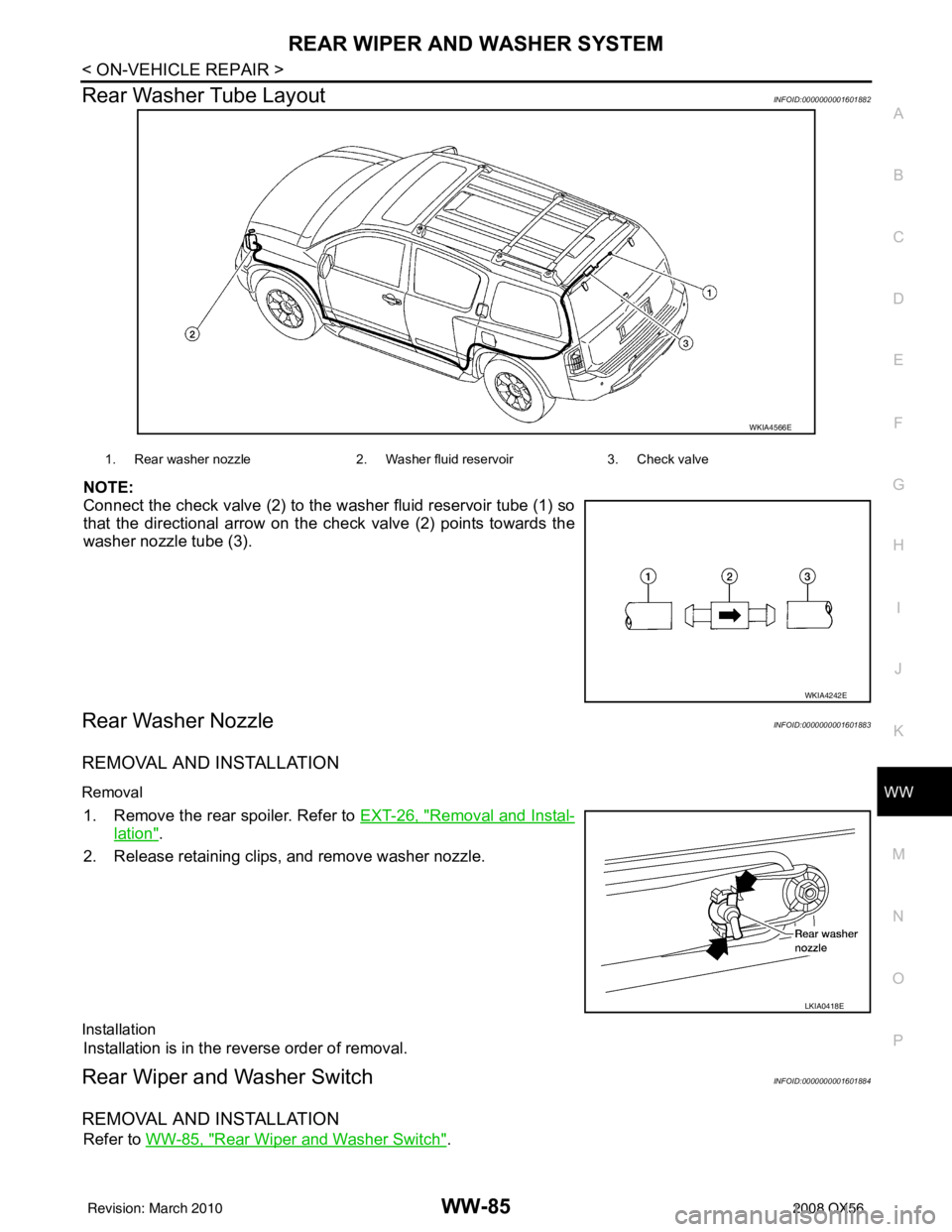
Rear Washer Tube LayoutINFOID:0000000001601882
NOTE:
Connect the check valve (2) to the washer fluid reservoir tube (1) so
that the directional arrow on the check valve (2) points towards the
washer nozzle tube (3).
Rear Washer NozzleINFOID:0000000001601883
REMOVAL AND INSTALLATION
Removal
1. Remove the rear spoiler. Refer to EXT-26, "Removal and Instal-
lation".
2. Release retaining clips, and remove washer nozzle.
Installation
Installation is in the reverse order of removal.
Rear Wiper and Washer SwitchINFOID:0000000001601884
REMOVAL AND INSTALLATION
Refer to WW-85, "Rear Wiper and Washer Switch".
WKIA4566E
1. Rear washer nozzle 2. Washer fluid reservoir3. Check valve
WKIA4242E
LKIA0418E
Revision: March 2010 2008 QX56