2008 INFINITI QX56 cooling
[x] Cancel search: coolingPage 3873 of 4083
DUCTS AND GRILLESVTL-33
< ON-VEHICLE REPAIR >
C
DE
F
G H
J
K L
M A
B
VTL
N
O P
Removal and InstallationINFOID:0000000001516623
CENTER CONSOLE HEAT DUCT AND RE AR FINISHER ASSEMBLY GRILLE
Removal
The center console must be removed and disassembled to remove the heat duct and rear finisher assembly
grille. Refer to IP-20, "
Removal and Installation".
Installation
Installation is in the reverse order of removal.
DEFROSTER NOZZLE
Removal
1. Remove the instrument panel trim. Refer to IP-12, "Removal and Installation".
2. Remove the front heater and cooling unit assembly. Refer to VTL-16, "
Removal and Installation".
3. Remove the defroster nozzle.
Installation
Installation is in the reverse order of removal.
RH AND LH SIDE DEMISTER DUCT
Removal
1. Remove the instrument panel trim. Refer to IP-12, "Removal and Installation".
2. Remove the RH or LH side demister duct screws.
3. Remove the RH or LH side demister duct.
Installation
Installation is in the reverse order of removal.
RH AND LH VENTILATOR DUCT
Removal
1. Remove the instrument panel trim. Refer to IP-12, "Removal and Installation".
2. Remove the front heater and cooling unit assembly. Refer to VTL-16, "
Removal and Installation".
3. Remove the RH or LH ventilator duct.
Installation
Installation is in the reverse order of removal.
CENTER VENTILATOR DUCT
Removal
1. Remove the instrument panel trim. Refer to IP-12, "Removal and Installation".
2. Remove the front heater and cooling unit assembly. Refer to VTL-16, "
Removal and Installation".
3. Remove the defroster nozzle.
4. Remove the RH and LH side demister ducts.
5. Remove the RH and LH ventilator ducts.
6. Remove the center ventilator duct.
Installation
Installation is in the reverse order of removal.
FLOOR DUCT
Removal
1. Remove the floor carpet. Refer to INT-16, "Removal and Installation".
2. Remove the two clips and remove the floor duct.
Installation
Installation is in the reverse order of removal.
Revision: March 2010 2008 QX56
Page 3875 of 4083
REFRIGERANT LINESVTL-35
< ON-VEHICLE REPAIR >
C
DE
F
G H
J
K L
M A
B
VTL
N
O P
REFRIGERANT LINES
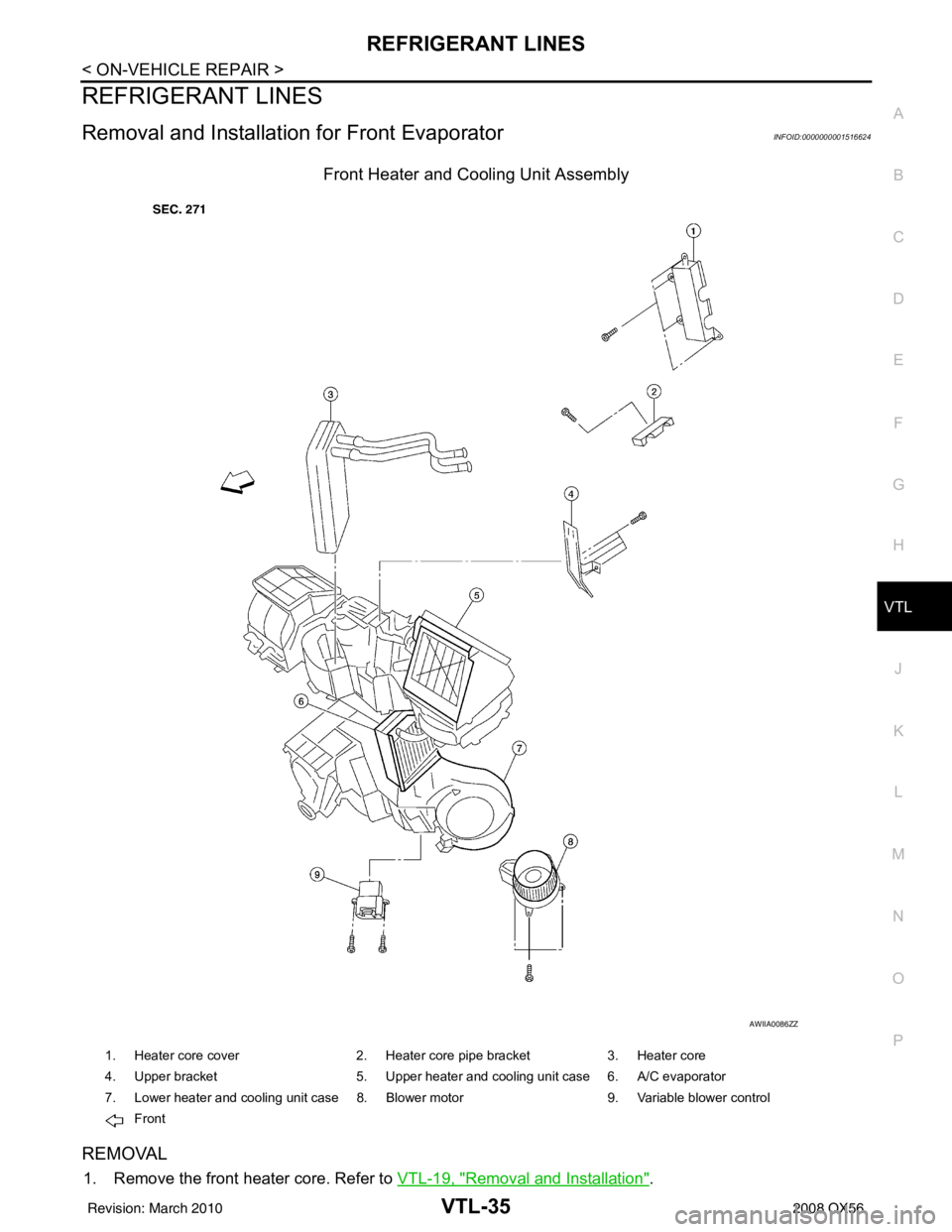
Removal and Installation for Front EvaporatorINFOID:0000000001516624
Front Heater and Cooling Unit Assembly
REMOVAL
1. Remove the front heater core. Refer to VTL-19, "Removal and Installation".
AWIIA0086ZZ
1. Heater core cover 2. Heater core pipe bracket3. Heater core
4. Upper bracket 5. Upper heater and cooling unit case 6. A/C evaporator
7. Lower heater and cooling unit case 8. Blower motor 9. Variable blower control
Front
Revision: March 2010 2008 QX56
Page 3876 of 4083

VTL-36
< ON-VEHICLE REPAIR >
REFRIGERANT LINES
2. Remove the defroster mode door arm.
3. Separate the heater core and cooling unit case.
4. Remove the evaporator.
INSTALLATION
Installation is in the reverse order of removal.
CAUTION:
• Replace the O-rings on the A/C refrigerant pipes with new ones, then apply compressor oil to them
when installing them.
• After charging the refrigerant, check for leaks.
Removal and Installation for Rear EvaporatorINFOID:0000000001516625
Rear Heater and Cooling Unit Assembly
AWIIA0087ZZ
1. Front cover 2. Evaporator and heater core case 3. Evaporator
4. Side cover 5. Heater core6. Blower motor
7. Blower motor case 8. Variable blower control
Front
Revision: March 2010 2008 QX56
Page 3877 of 4083
REFRIGERANT LINESVTL-37
< ON-VEHICLE REPAIR >
C
DE
F
G H
J
K L
M A
B
VTL
N
O P
REMOVAL
1. Remove the rear heater and cooling unit assembly from the vehicle. Refer to VTL-16, "Removal and
Installation".
2. Remove the blower motor.
3. Remove the variable blower control.
4. Remove the air mix door motor.
5. Remove the mode door motor.
6. Remove the rear duct and mode door assembly. Refer to VTL-33, "
Removal and Installation".
7. Disassemble the rear heater and cooling unit assembly to remove the evaporator.
INSTALLATION
Installation is in the reverse order of removal.
CAUTION:
• Replace the O-rings on the rear A/C pipes with new ones. Apply compressor oil to the O-rings when installing them.
• After charging the refrigerant, check for leaks.
Removal and Installation for Rear Expansion ValveINFOID:0000000001516626
REMOVAL
1. Discharge the refrigerant. Refer to HA-20, "HFC-134a (R-134a) Service Procedure".
2. Remove the luggage side finisher lower (RH). Refer to INT-19, "
Removal and Installation".
3. Disconnect the A/C refrigerant pi pes from the expansion valve.
CAUTION:
Cap or wrap the A/C refrigerant pipe ends with a suitable material such as vinyl tape to avoid the
entry of air and contaminants.
4. Remove the expansion valve.
INSTALLATION
Installation is in the reverse order of removal.
CAUTION:
• Replace the O-rings on the A/C refrigerant pipes with new ones, th en apply compressor oil to them
when installing them.
• After charging the refrigerant, check for leaks. Expansion valve bolts : 4 N·m (0.41 kg-m, 35 in-lb)
A/C refrigerant pipe to expansion valve bolt : Refer to HA-29, "
Component".
Revision: March 2010
2008 QX56
Page 4010 of 4083
DIAGNOSIS SYSTEM (IPDM E/R)WW-13
< FUNCTION DIAGNOSIS >
C
DE
F
G H
I
J
K
M A
B
WW
N
O P
DIAGNOSIS SYSTEM (IPDM E/R)
Diagnosis DescriptionINFOID:0000000004874864
AUTO ACTIVE TEST
Description
In auto active test mode, the IPDM E/R sends a drive signal to the following systems to check their operation.
• Oil pressure low/coolant pressure high warning indicator
• Oil pressure gauge
• Rear window defogger
• Front wipers
• Tail, license and parking lamps
• Front fog lamps
• Headlamps (Hi, Lo)
• A/C compressor (magnetic clutch)
• Cooling fan
Operation Procedure
1. Close the hood and front door RH, and lift the wiper arms from the windshield (to prevent windshield dam-
age due to wiper operation).
NOTE:
When auto active test is performed with hood opened, sprinkle water on windshield before hand.
2. Turn ignition switch OFF.
3. Turn the ignition switch ON and, within 20 seconds, press the front door switch LH 10 times. Then turn the ignition switch OFF.
4. Turn the ignition switch ON within 10 seconds. Af ter that the horn sounds once and the auto active test
starts.
5. After a series of the following operations is repeated 3 times, auto active test is completed.
NOTE:
When auto active test mode has to be cancelled halfway through test, turn ignition switch OFF.
CAUTION:
• If auto active test mode cannot be actua ted, check door switch system. Refer to DLK-67, "
Descrip-
tion".
• Do not start the engine.
Inspection in Auto Active Test Mode
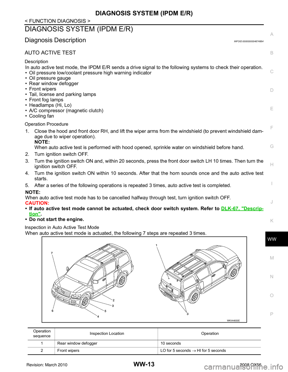
When auto active test mode is actuated, the following 7 steps are repeated 3 times.
Operation
sequence Inspection Location
Operation
1 Rear window defogger 10 seconds
2 Front wipers LO for 5 seconds → HI for 5 seconds
WKIA4655E
Revision: March 2010 2008 QX56
Page 4011 of 4083
WW-14
< FUNCTION DIAGNOSIS >
DIAGNOSIS SYSTEM (IPDM E/R)
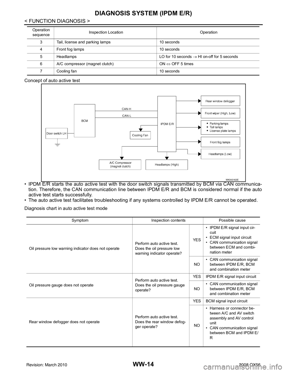
Concept of auto active test
• IPDM E/R starts the auto active test with the door switch signals transmitted by BCM via CAN communica-
tion. Therefore, the CAN communication line between IPDM E/R and BCM is considered normal if the auto
active test starts successfully.
• The auto active test facilitates troubleshooting if any systems controlled by IPDM E/R cannot be operated.
Diagnosis chart in auto active test mode
3 Tail, license and parking lamps 10 seconds
4 Front fog lamps 10 seconds
5 Headlamps LO for 10 seconds → HI on-off for 5 seconds
6 A/C compressor (magnet clutch) ON ⇔ OFF 5 times
7 Cooling fan 10 seconds
Operation
sequence Inspection Location
Operation
WKIA5163E
SymptomInspection contentsPossible cause
Oil pressure low warning indicator does not operate Perform auto active test.
Does the oil pressure low
warning indicator operate?YES
• IPDM E/R signal input cir-
cuit
• ECM signal input circuit
• CAN communication signal between ECM and combi-
nation meter
NO • CAN communication signal
between IPDM E/R, BCM
and combination meter
Oil pressure gauge does not operate Perform auto active test.
Does the oil pressure gauge
operate?YES IPDM E/R signal input circuit
NO • CAN communication signal
between IPDM E/R, BCM
and combination meter
Rear window defogger does not operate Perform auto active test.
Does the rear window defog-
ger operate?YES BCM signal input circuit
NO • Harness or connector be-
tween A/C and AV switch
assembly and AV control
unit
• CAN communication signal between BCM and IPDM E/
R
Revision: March 2010 2008 QX56
Page 4012 of 4083
DIAGNOSIS SYSTEM (IPDM E/R)WW-15
< FUNCTION DIAGNOSIS >
C
DE
F
G H
I
J
K
M A
B
WW
N
O P
CONSULT - III Function (IPDM E/R)INFOID:0000000004874867
APPLICATION ITEM
CONSULT-III performs the following functions via CAN communication with IPDM E/R.
SELF DIAGNOSTIC
Refer to PCS-31, "DTCIndex".
DATA MONITOR
Monitor item
Any of the following components do not operate
• Front wipers
•Tail lamps
• License plate lamps
•Parking lamps
• Front fog lamps
• Headlamps (Hi, Lo) Perform auto active test.
Does the applicable system
operate?YES BCM signal input system
NO • Lamp or front wiper motor
malfunction
• Lamp or front wiper motor ground circuit
• Harness or connector be-
tween IPDM E/R and appli-
cable system
• IPDM E/R (integrated relay
malfunction)
A/C compressor does not operate Perform auto active test.
Does the A/C compressor op-
erate?YES
• BCM signal input circuit
• CAN communication signal
between BCM and ECM
• CAN communication signal between ECM and IPDM E/
R
NO • Magnetic clutch malfunction
• Harness or connector be-
tween IPDM E/R and mag-
netic clutch
• IPDM E/R (integrated relay malfunction)
Cooling fan does not operate Perform auto active test.
Does the cooling fan operate?YES
• ECM signal input circuit
• CAN communication signal
between ECM and IPDM E/
R
NO • Cooling fan motor malfunc-
tion
• Harness or connector be- tween IPDM E/R and cool-
ing fan
• IPDM E/R (integrated relay malfunction)
Symptom
Inspection contentsPossible cause
Diagnosis mode Description
ECU Identification Allows confirmation of IPDM E/R part number.
Self Diagnostic Result Displays the diagnosis results judged by IPDM E/R.
Data Monitor Displays the real-time input/output data from IPDM E/R input/output data.
Active Test IPDM E/R can provide a drive signal to electronic components to check their operations.
CAN Diag Support Monitor The results of transmit/receive diagnosis of CAN communication can be read.
Revision: March 2010 2008 QX56
Page 4013 of 4083
![INFINITI QX56 2008 Factory Service Manual WW-16
< FUNCTION DIAGNOSIS >
DIAGNOSIS SYSTEM (IPDM E/R)
ACTIVE TEST
Te s t i t e m
Monitor Item[Unit] MAIN SIG-
NALS Description
MOTOR FAN REQ
[1/2/3/4] ×Displays the status of the cooling fan spee INFINITI QX56 2008 Factory Service Manual WW-16
< FUNCTION DIAGNOSIS >
DIAGNOSIS SYSTEM (IPDM E/R)
ACTIVE TEST
Te s t i t e m
Monitor Item[Unit] MAIN SIG-
NALS Description
MOTOR FAN REQ
[1/2/3/4] ×Displays the status of the cooling fan spee](/manual-img/42/57030/w960_57030-4012.png)
WW-16
< FUNCTION DIAGNOSIS >
DIAGNOSIS SYSTEM (IPDM E/R)
ACTIVE TEST
Te s t i t e m
Monitor Item[Unit] MAIN SIG-
NALS Description
MOTOR FAN REQ
[1/2/3/4] ×Displays the status of the cooling fan speed request signal received from ECM via
CAN communication.
A/C COMP REQ
[OFF/ON] ×Displays the status of the A/C request signal received from AV control unit via
CAN communication.
TA I L & C L R R E Q
[OFF/ON] ×
Displays the status of the position light request signal received from BCM via CAN
communication.
HL LO REQ
[OFF/ON] ×Displays the status of the low beam request signal received from BCM via CAN
communication.
HL HI REQ
[OFF/ON] ×Displays the status of the high beam request signal received from BCM via CAN
communication.
FR FOG REQ
[OFF/ON] ×
Displays the status of the front fog lamp request signal received from BCM via
CAN communication.
HL WASHER REQ
[OFF/ON] NOTE:
This item is displayed, but cannot be monitored.
FR WIP REQ
[STOP/1LOW/LOW/HI] ×Displays the status of the front wiper request signal received from BCM via CAN
communication.
WIP AUTO STOP
[STOP P/ACT P] ×
Displays the status of the front wiper auto stop signal judged by IPDM E/R.
WIP PROT
[OFF/Block] ×
Displays the status of the front wiper fail-safe operation judged by IPDM E/R.
ST RLY REQ
[OFF/ON] Displays the status of the starter request signal received from ECM via CAN com-
munication.
IGN RLY
[OFF/ON] ×
Displays the status of the ignition relay judged by IPDM E/R.
RR DEF REQ
[OFF/ON] ×Displays the status of the rear defogger request signal received from AV control
unit via CAN communication.
OIL P SW
[OPEN/CLOSE] Displays the status of the oil pressure switch judged by IPDM E/R.
DTRL REQ
[OFF] Displays the status of the daytime light request signal received from BCM via CAN
communication.
HOOD SW
[OPEN/CLOSE] Displays the status of the hood switch judged by IPDM E/R.
THFT HRN REQ
[OFF/ON] Displays the status of the theft warning horn request signal received from BCM
via CAN communication.
HORN CHIRP
[OFF/ON] Displays the status of the horn reminder signal received from BCM via CAN com-
munication.
Test item
Operation Description
REAR DEFOGGER OFF
OFF
ON Operates rear window defogger relay.
FRONT WIPER OFF
OFF
LO Operates the front wiper relay.
HI Operates the front wiper relay and front wiper high relay.
MOTOR FAN 1O
FF
2O FF
3 Operates the cooling fan relay.
4 Operates the cooling fan relay.
Revision: March 2010 2008 QX56