2008 INFINITI QX56 cooling
[x] Cancel search: coolingPage 3722 of 4083
PRECAUTIONSTM-175
< PRECAUTION >
CEF
G H
I
J
K L
M A
B
TM
N
O P
• All parts should be carefully cleaned with a general purpose, non-flammable solvent before inspection or reassembly.
• Gaskets, seals and O-rings should be replaced any time the transmission is disassembled.
• It is very important to perform func tional tests whenever they are indicated.
• The valve body contains precision parts and requires extreme care when parts are removed and serviced. Place disassembled valve body parts in order for easier and proper assembly. Care will also prevent springs
and small parts from becoming scattered or lost.
• Properly installed valves, sleeves, plugs, etc. will slide along bores in valve body under their own weight.
• Before assembly, apply a coat of recommended ATF to all parts. Apply petroleum jelly to protect O-rings and
seals, or hold bearings and washers in pl ace during assembly. Do not use grease.
• Extreme care should be taken to avoid damage to O-rings, seals and gaskets when assembling.
• Clean or replace ATF cooler if excessive foreign material is found in oil pan or clogging strainer. Refer to TM-
182, "A/T Fluid Cooler Cleaning".
• After overhaul, refill the transmission with new ATF.
• When the A/T drain plug is removed, only some of the fluid is drained. Old A/T fluid will remain in torque con- verter and ATF cooling system.
Always follow the procedures under “Changing A/T Fluid” in the AT section when changing A/T fluid. Refer to
TM-180, "
Changing the A/T Fluid (ATF)".
Service Notice or PrecautionINFOID:0000000001531487
ATF COOLER SERVICE
• If A/T fluid contains fictional material (clutches, bands, etc.), or if an A/T is repaired, overhauled, or replaced,
inspect and clean the A/T fluid cooler mounted in the radiat or or replace the radiator. Flush cooler lines with
cleaning solvent and compressed air after repair. For A/T fluid cooler cleaning procedure, refer to TM-182,
"A/T Fluid Cooler Cleaning". For radiator replacement, refer to CO-15, "Removal and Installation".
CHECKING AND CHANGING A/T FLUID
• Increase ATF oil temperature to 80 °C (176° F) first, then check and adjust oil level at 65 °C (149° F).
NOTE:
The A/T has both water cooling and air cooling systems. The air cooling system has a bypass valve. When
ATF oil temperature is at or below 50 °C (122° F), it does not flow through the air cooled system. If A/T oil
level is adjusted without flow throughout the entir e system, the level will be 10mm lower than required.
Therefore, all piping should be filled with oil when adjusting level.
OBD-II SELF-DIAGNOSIS
• A/T self-diagnosis is performed by the TCM in combination with the ECM. Refer to the table on TM-32,
"CONSULT-III Function (TRANSMISSION)" for the indicator used to display each self-diagnostic result.
• The self-diagnostic results indicated by the MIL are automatically stored in both the ECM and TCM memo- ries.
Always perform the procedure on TM-30, "
OBD-II Diagnostic Trouble Code (DTC)" to complete the
repair and avoid unnecessary blinking of the MIL.
For details of OBD-II, refer to TM-30
.
• Certain systems and components, especially those related to OBD, may use the new style slide-
locking type harness connector. For descrip tion and how to disconnect, refer to PG-65
.
Revision: March 2010 2008 QX56
Page 3726 of 4083
A/T FLUIDTM-179
< ON-VEHICLE MAINTENANCE >
CEF
G H
I
J
K L
M A
B
TM
N
O P
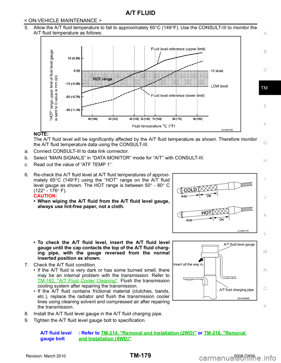
5. Allow the A/T fluid temperature to fall to approximately 65 °C (149° F). Use the CONSULT-III to monitor the
A/T fluid temperature as follows:
NOTE:
The A/T fluid level will be significantly affected by the A/T fluid temperature as shown. Therefore monitor
the A/T fluid temperature data using the CONSULT-III.
a. Connect CONSULT-III to data link connector.
b. Select “MAIN SIGNALS” in “DATA MO NITOR” mode for “A/T” with CONSULT-III.
c. Read out the value of “ATF TEMP 1”.
6. Re-check the A/T fluid level at A/T fluid temperatures of approxi-
mately 65° C (149°F) using the “HOT” range on the A/T fluid
level gauge as shown. The HOT range is between 50 ° - 80° C
(122° - 176 ° F).
CAUTION:
• When wiping the A/T fluid from the A/T fluid level gauge, always use lint-free paper, not a cloth.
• To check the A/T fluid level, insert the A/T fluid level gauge until the cap contacts the top of the A/T fluid charg-
ing pipe, with the gauge reversed from the normal
inserted position as shown.
7. Check the A/T fluid condition. • If the A/T fluid is very dark or has some burned smell, there
may be an internal problem with the transmission. Refer to
TM-182, "
A/T Fluid Cooler Cleaning". Flush the transmission
cooling system after repairing the transmission.
• If the A/T fluid contains frictional material (clutches, bands, etc.), replace the radiator and flush the transmission cooler
lines using cleaning solvent and compressed air after repairing
the transmission.
8. Install the A/T fluid level gauge in the A/T fluid charging pipe.
9. Tighten the A/T fluid level gauge bolt to specification.
SLIA0016E
LLIA0071E
A/T fluid level
gauge bolt : Refer to
TM-214, "Removal and Installation (2WD)" or TM-216, "Removal
and Installation (4WD)"
SCIA2899E
Revision: March 2010 2008 QX56
Page 3841 of 4083

VTL-1
VENTILATION, HEATER & AIR CONDITIONER
C
DE
F
G H
J
K L
M
SECTION VTL
A
B
VTL
N
O P
CONTENTS
VENTILATION SYSTEM
PRECAUTION ....... ........................................2
PRECAUTIONS .............................................. .....2
Precaution for Supplemental Restraint System
(SRS) "AIR BAG" and "SEAT BELT PRE-TEN-
SIONER" ............................................................. ......
2
Precaution Necessary for Steering Wheel Rota-
tion After Battery Disconnect ............................... ......
2
Precaution for Working with HFC-134a (R-134a) ......3
Precaution for Procedure without Cowl Top Cover ......3
PREPARATION ............................................4
PREPARATION .............................................. .....4
Commercial Service Tool .................................... ......4
FUNCTION DIAGNOSIS ...............................5
IN-CABIN MICROFILTER .............................. .....5
Description .......................................................... ......5
ON-VEHICLE MAINTENANCE .....................6
IN-CABIN MICROFILTER .............................. .....6
Removal and Installation ...........................................6
ON-VEHICLE REPAIR .... ..............................7
CONTROL UNIT ..................................................7
Removal and Installation ...........................................7
IN-VEHICLE SENSOR ................................... .....9
Removal and Installation ...........................................9
OPTICAL SENSOR ........................................ ....10
Removal and Installation .........................................10
INTAKE SENSOR ..............................................11
Removal and Installation .........................................11
BLOWER MOTOR .......................................... ....12
Component .......................................................... ....12
Removal and Installation ..................................... ....12
IN-CABIN MICROFILTER .................................14
Removal and Installation .........................................14
HEATER & COOLING UNIT ASSEMBLY ........15
Component ..............................................................15
Removal and Installation .........................................16
HEATER CORE .................................................18
Component ..............................................................18
Removal and Installation .........................................19
DEFROSTER DOOR MOTOR ..........................21
Removal and Installation .........................................21
INTAKE DOOR MOTOR ...................................22
Removal and Installation .........................................22
MODE DOOR MOTOR ......................................23
Components ............................................................23
Removal and Installation .........................................24
AIR MIX DOOR MOTOR ...................................25
Component ..............................................................25
Removal and Installation .........................................26
VARIABLE BLOWER CONTROL .....................28
Components ............................................................28
Removal and Installation .........................................29
DUCTS AND GRILLES .....................................30
Component ..............................................................30
Removal and Installation .........................................33
REFRIGERANT LINES .....................................35
Removal and Installation for Front Evaporator ........35
Removal and Installation for Rear Evaporator .........36
Removal and Installation for Rear Expansion
Valve ........................................................................
37
Revision: March 2010 2008 QX56
Page 3845 of 4083
IN-CABIN MICROFILTERVTL-5
< FUNCTION DIAGNOSIS >
C
DE
F
G H
J
K L
M A
B
VTL
N
O P
FUNCTION DIAGNOSIS
IN-CABIN MICROFILTER
DescriptionINFOID:0000000001516601
FUNCTION
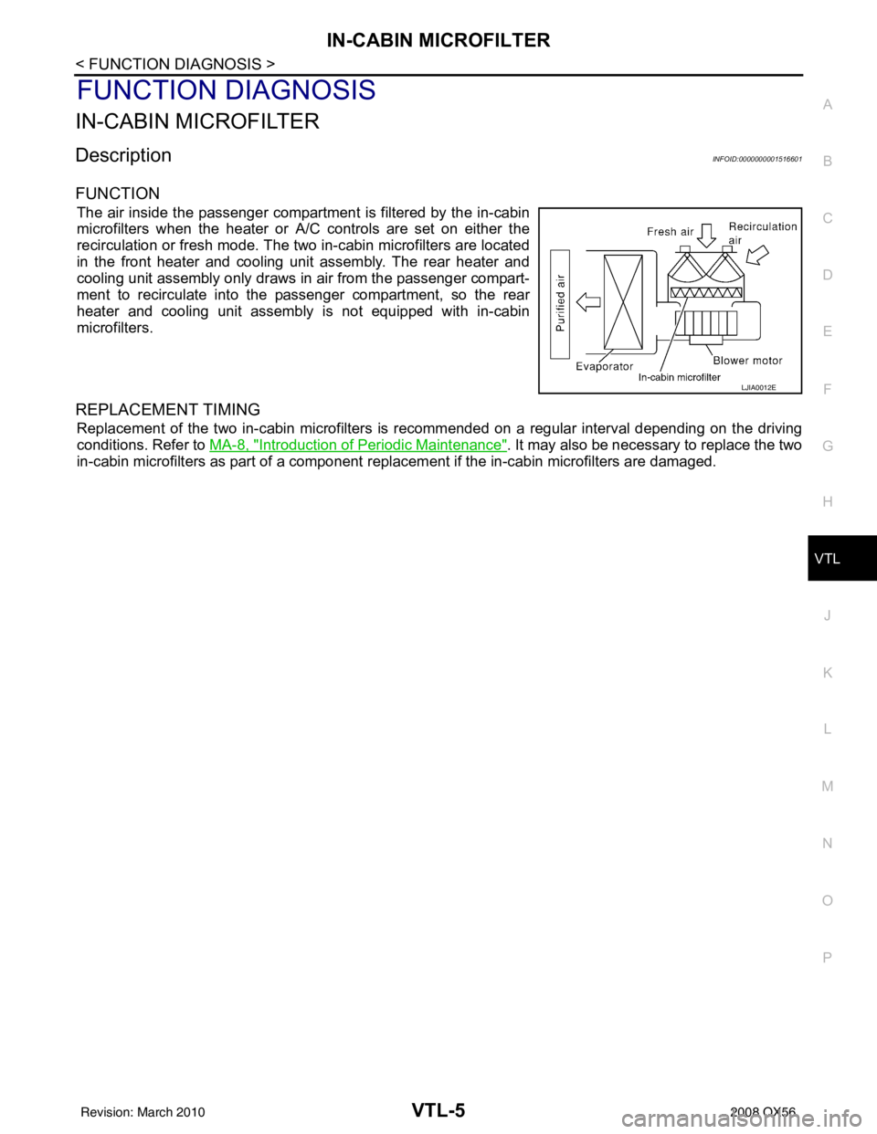
The air inside the passenger compartment is filtered by the in-cabin
microfilters when the heater or A/C controls are set on either the
recirculation or fresh mode. The two in-cabin microfilters are located
in the front heater and cooling unit assembly. The rear heater and
cooling unit assembly only draws in air from the passenger compart-
ment to recirculate into the passenger compartment, so the rear
heater and cooling unit assembly is not equipped with in-cabin
microfilters.
REPLACEMENT TIMING
Replacement of the two in-cabin microfilters is recommended on a regular interval depending on the driving
conditions. Refer to MA-8, "
Introduction of Periodic Maintenance". It may also be necessary to replace the two
in-cabin microfilters as part of a component r eplacement if the in-cabin microfilters are damaged.
LJIA0012E
Revision: March 2010 2008 QX56
Page 3846 of 4083
VTL-6
< ON-VEHICLE MAINTENANCE >
IN-CABIN MICROFILTER
ON-VEHICLE MAINTENANCE
IN-CABIN MICROFILTER
Removal and InstallationINFOID:0000000001516602
REPLACEMENT PROCEDURE
1. Remove the glove box assembly from the instrument panel. Refer to IP-17, "Removal and Installation".
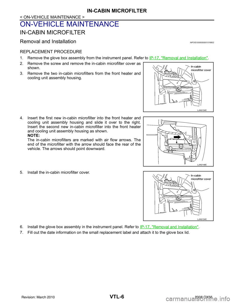
2. Remove the screw and remove the in-cabin microfilter cover as shown.
3. Remove the two in-cabin microf ilters from the front heater and
cooling unit assembly housing.
4. Insert the first new in-cabin micr ofilter into the front heater and
cooling unit assembly housing and slide it over to the right.
Insert the second new in-cabin mi crofilter into the front heater
and cooling unit assembly housing as shown.
NOTE:
The in-cabin microfilters are marked with air flow arrows. The
end of the microfilter with the arro w should face the rear of the
vehicle. The arrows should point downward.
5. Install the in-cabin microfilter cover.
6. Install the glove box assembly in the instrument panel. Refer to IP-17, "
Removal and Installation".
7. Fill out the date information on the small replac ement label and attach it to the glove box lid.
LJIA0134E
LJIA0148E
LJIA0134E
Revision: March 2010 2008 QX56
Page 3851 of 4083
INTAKE SENSORVTL-11
< ON-VEHICLE REPAIR >
C
DE
F
G H
J
K L
M A
B
VTL
N
O P
INTAKE SENSOR
Removal and InstallationINFOID:0000000001516606
REMOVAL
1. Remove the instrument panel. Refer to IP-12, "Removal and Installation".
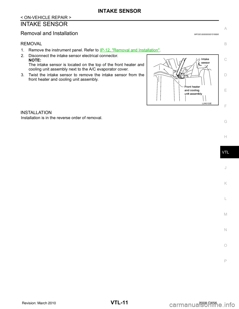
2. Disconnect the intake sensor electrical connector. NOTE:
The intake sensor is located on the top of the front heater and
cooling unit assembly next to the A/C evaporator cover.
3. Twist the intake sensor to remove the intake sensor from the front heater and cooling unit assembly.
INSTALLATION
Installation is in the reverse order of removal.
LJIA0133E
Revision: March 2010 2008 QX56
Page 3852 of 4083
VTL-12
< ON-VEHICLE REPAIR >
BLOWER MOTOR
BLOWER MOTOR
ComponentINFOID:0000000001516607
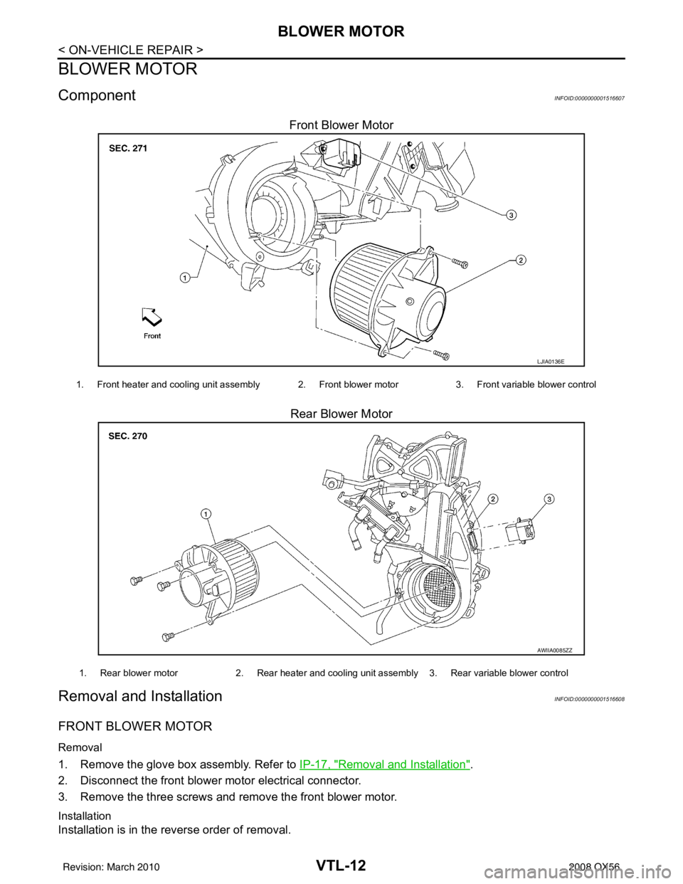
Front Blower MotorRear Blower Motor
Removal and InstallationINFOID:0000000001516608
FRONT BLOWER MOTOR
Removal
1. Remove the glove box assembly. Refer to IP-17, "Removal and Installation".
2. Disconnect the front blower motor electrical connector.
3. Remove the three screws and remove the front blower motor.
Installation
Installation is in the reverse order of removal.
LJIA0136E
1. Front heater and cooling unit assembly 2. Front blower motor 3. Front variable blower control
AWIIA0085ZZ
1. Rear blower motor2. Rear heater and cooling unit assembly 3. Rear variable blower control
Revision: March 2010 2008 QX56
Page 3854 of 4083
VTL-14
< ON-VEHICLE REPAIR >
IN-CABIN MICROFILTER
IN-CABIN MICROFILTER
Removal and InstallationINFOID:0000000001516609
REPLACEMENT PROCEDURE
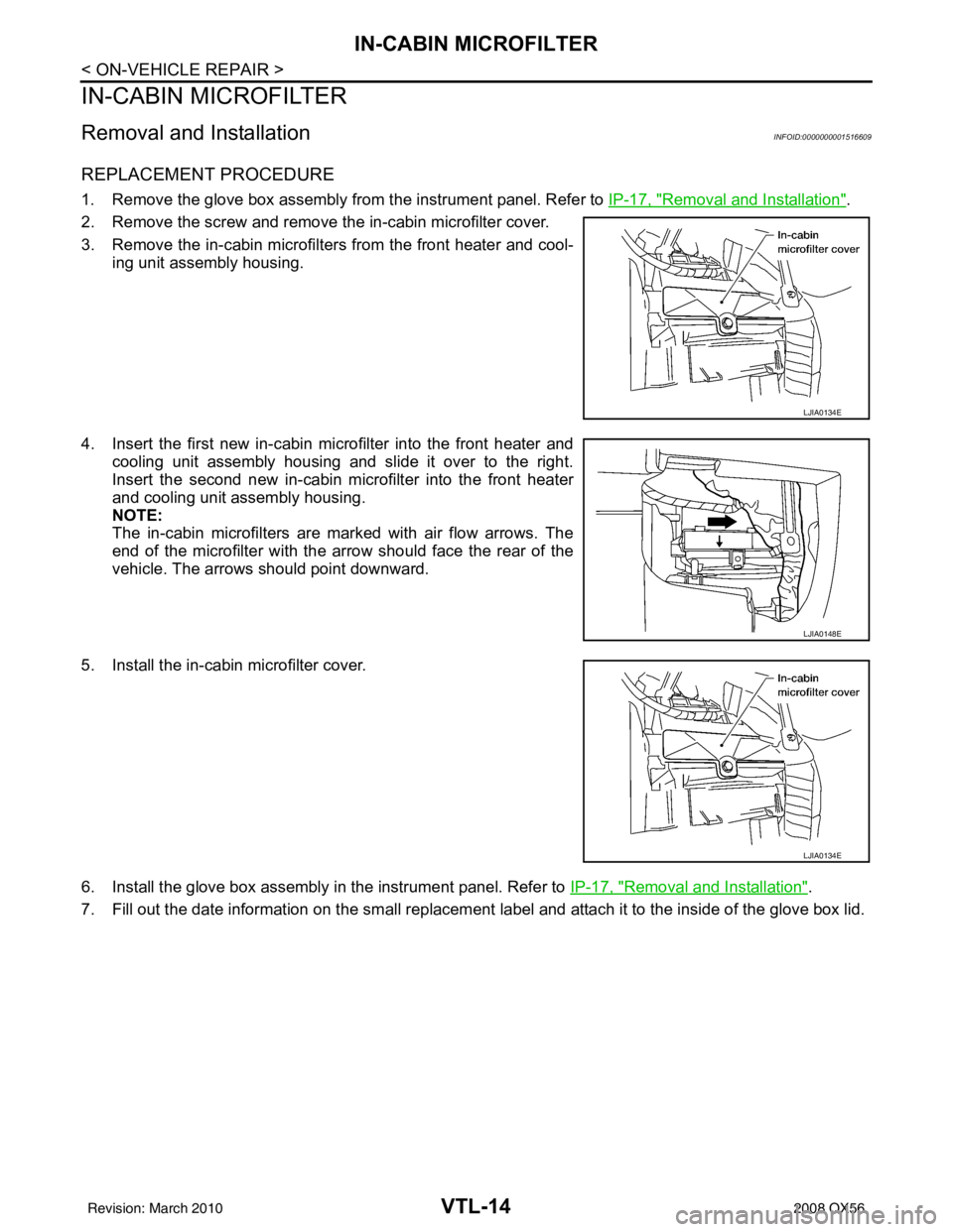
1. Remove the glove box assembly from the instrument panel. Refer to IP-17, "Removal and Installation".
2. Remove the screw and remove the in-cabin microfilter cover.
3. Remove the in-cabin microfilters from the front heater and cool- ing unit assembly housing.
4. Insert the first new in-cabin micr ofilter into the front heater and
cooling unit assembly housing and slide it over to the right.
Insert the second new in-cabin mi crofilter into the front heater
and cooling unit assembly housing.
NOTE:
The in-cabin microfilters are marked with air flow arrows. The
end of the microfilter with the arro w should face the rear of the
vehicle. The arrows should point downward.
5. Install the in-cabin microfilter cover.
6. Install the glove box assembly in the instrument panel. Refer to IP-17, "
Removal and Installation".
7. Fill out the date information on the sm all replacement label and attach it to the inside of the glove box lid.
LJIA0134E
LJIA0148E
LJIA0134E
Revision: March 2010 2008 QX56