Page 3019 of 3924
IP-18
< SERVICE INFORMATION >
INSTRUMENT PANEL ASSEMBLY
Disassembly
1. Insert a remover into side between gaps console rear finisher and pull back to your side, and disconnectpawls below.
2. Disconnect harness connector and remove console rear finisher.
3. Insert a remover into side between gaps of console mask and pull back to your side.
4. Remove screws with power tool and remove console lid.
5. Remove screws fixing DVD player with power tool.
6. Disconnect harness connectors, and remove DVD player.
Assembly
Assemble in the reverse order of disassembly.
INSTRUMENT PASSENGER LOWER PANEL
1. Console lid 2. Console mask 3. Console body
4. DVD player bracket 5. DVD player 6. Console rear finisher
Clip Pawl
PIIB8538E
3AA93ABC3ACD3AC03ACA3AC03AC63AC53A913A773A893A873A873A8E3A773A983AC73AC93AC03AC3
3A893A873A873A8F3A773A9D3AAF3A8A3A8C3A863A9D3AAF3A8B3A8C
Page 3020 of 3924
INSTRUMENT PANEL ASSEMBLYIP-19
< SERVICE INFORMATION >
C
DE
F
G H
J
K L
M A
B
IP
N
O P
Disassembly
1. Detach the damper from glove box assembly right side.
2. Remove glove box pins and remove glove box assembly.
3. Remove screws with power tool and remove glove box striker.
Assembly
Assemble in the reverse order of disassembly.
1. Instrument passenger lower panel 2. Glove box 3. Glove box pin
4. Glove box striker 5. Screw
PIIA5012E
PIIA4999E
PIIA5000E
3AA93ABC3ACD3AC03ACA3AC03AC63AC53A913A773A893A873A873A8E3A773A983AC73AC93AC03AC3
3A893A873A873A8F3A773A9D3AAF3A8A3A8C3A863A9D3AAF3A8B3A8C
Page 3267 of 3924

INTERIOR ROOM LAMPLT-165
< SERVICE INFORMATION >
C
DE
F
G H
I
J
L
M A
B
LT
N
O P
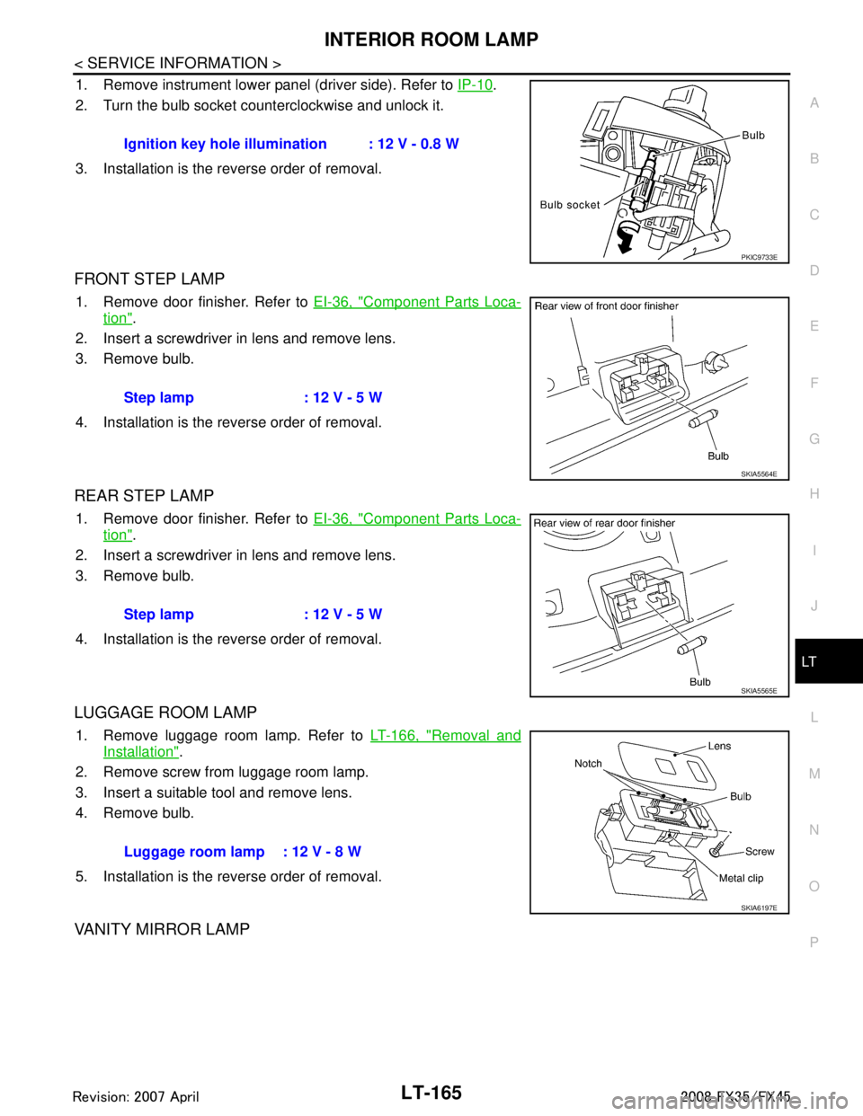
1. Remove instrument lower panel (driver side). Refer to IP-10.
2. Turn the bulb socket counterclockwise and unlock it.
3. Installation is the reverse order of removal.
FRONT STEP LAMP
1. Remove door finisher. Refer to EI-36, "Component Parts Loca-
tion".
2. Insert a screwdriver in lens and remove lens.
3. Remove bulb.
4. Installation is the reverse order of removal.
REAR STEP LAMP
1. Remove door finisher. Refer to EI-36, "Component Parts Loca-
tion".
2. Insert a screwdriver in lens and remove lens.
3. Remove bulb.
4. Installation is the reverse order of removal.
LUGGAGE ROOM LAMP
1. Remove luggage room lamp. Refer to LT-166, "Removal and
Installation".
2. Remove screw from luggage room lamp.
3. Insert a suitable tool and remove lens.
4. Remove bulb.
5. Installation is the reverse order of removal.
VANITY MIRROR LAMP
Ignition key hole illumination : 12 V - 0.8 W
PKIC9733E
Step lamp : 12 V - 5 W
SKIA5564E
Step lamp : 12 V - 5 W
SKIA5565E
Luggage room lamp : 12 V - 8 W
SKIA6197E
3AA93ABC3ACD3AC03ACA3AC03AC63AC53A913A773A893A873A873A8E3A773A983AC73AC93AC03AC3
3A893A873A873A8F3A773A9D3AAF3A8A3A8C3A863A9D3AAF3A8B3A8C
Page 3283 of 3924
ILLUMINATIONLT-181
< SERVICE INFORMATION >
C
DE
F
G H
I
J
L
M A
B
LT
N
O P
Bulb ReplacementINFOID:0000000001328427
GLOVE BOX LAMP
1. Remove instrument passenger lower panel. Refer to IP-16, "Disassembly and Assembly".
TKWM4337E
3AA93ABC3ACD3AC03ACA3AC03AC63AC53A913A773A893A873A873A8E3A773A983AC73AC93AC03AC3
3A893A873A873A8F3A773A9D3AAF3A8A3A8C3A863A9D3AAF3A8B3A8C
Page 3284 of 3924
LT-182
< SERVICE INFORMATION >
ILLUMINATION
2. Turn bulb socket left to release lock and remove it.
3. Installation is the reverse order of removal.
A/T DEVICE ILLUMINATION
1. Remove A/T console finisher. Refer to IP-10.
2. Turn bulb socket left to release lock and remove it.
3. Installation is the reverse order of removal.
COIN BOX ILLUMINATION
1. Remove instrument clock finisher. Refer to IP-10.
2. Turn bulb socket left to release lock and remove it.
3. Installation is the reverse order of removal.
Removal and InstallationINFOID:0000000001328428
ILLUMINATION CONTROL SWITCH
Refer to DI-24, "Removal and Installation of Odo/Trip Meter and Illumination Control Switch".
Glove box lamp : 12 V - 1.4 W
PKIB3636E
A/T device illumination : 12 V - 1.4 W
PKIC9699E
Coin box illumination : 12 V - 1.4 W
PKIC9698E
3AA93ABC3ACD3AC03ACA3AC03AC63AC53A913A773A893A873A873A8E3A773A983AC73AC93AC03AC3
3A893A873A873A8F3A773A9D3AAF3A8A3A8C3A863A9D3AAF3A8B3A8C
Page 3359 of 3924

PB-4
< SERVICE INFORMATION >
PARKING BRAKE CONTROL
PARKING BRAKE CONTROL
ComponentINFOID:0000000001327647
Removal and InstallationINFOID:0000000001327648
REMOVAL
1. Remove front kicking plate (driver side). Refer to IP-11, "Removal and Installation".
2. Remove front body side welt (driver side). Refer to EI-38
.
3. Remove dash side finisher (driver side). Refer to IP-10
.
4. Remove instrument lower panel (driver side). Refer to IP-10
.
5. Remove adjusting nut.
6. Remove front cable installation bolts, nuts, and lock plate, then remove front cable from the vehicle.
7. Remove heat insulator between center muffler and rear propeller shaft.
8. Remove exhaust center muffler. Refer to EX-3
.
9. Remove propeller shaft. Refer to PR-9, "
Removal and Installation".
10. Remove rear disc caliper and disc rotors. Refer to BR-25, "
Removal and Installation of Brake Caliper
Assembly".
11. Remove parking brake shoe, and remove r ear cable from toggle lever. Refer to PB-6
.
1. Device assembly 2. Spring insulator 3. Return spring
4. Lock plate 5. Front cable 6. Return spring
7. Rear left cable 8. Rear right cable 9. Pin
10. Adjusting nut
SFIA1943E
3AA93ABC3ACD3AC03ACA3AC03AC63AC53A913A773A893A873A873A8E3A773A983AC73AC93AC03AC3
3A893A873A873A8F3A773A9D3AAF3A8A3A8C3A863A9D3AAF3A8B3A8C
Page 3467 of 3924

PS-12
< SERVICE INFORMATION >
STEERING COLUMN
STEERING COLUMN
Removal and InstallationINFOID:0000000001327714
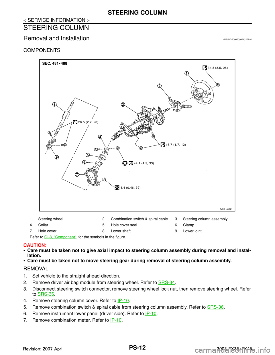
COMPONENTS
CAUTION:
Care must be taken not to give axial impact to steering column assembly during removal and instal-
lation.
Care must be taken not to move steering gear during removal of steering column assembly.
REMOVAL
1. Set vehicle to the straight ahead-direction.
2. Remove driver air bag module from steering wheel. Refer to SRS-34
.
3. Disconnect steering switch connector, remove steering wheel lock nut, then remove steering wheel. Refer to SRS-36
.
4. Remove steering column cover. Refer to IP-10
.
5. Remove combination switch & spiral cabl e from steering column assembly. Refer to SRS-36
.
6. Remove instrument lower panel (driver side). Refer to IP-10
.
7. Remove combination meter. Refer to IP-10
.
1. Steering wheel 2. Combination switch & spiral cable 3. Steering column assembly
4. Collar 5. Hole cover seal 6. Clamp
7. Hole cover 8. Lower shaft 9. Lower joint
Refer to GI-8, "
Component", for the symbols in the figure.
SGIA1612E
3AA93ABC3ACD3AC03ACA3AC03AC63AC53A913A773A893A873A873A8E3A773A983AC73AC93AC03AC3
3A893A873A873A8F3A773A9D3AAF3A8A3A8C3A863A9D3AAF3A8B3A8C
Page 3520 of 3924

SQUEAK AND RATTLE TROUBLE DIAGNOSESRF-5
< SERVICE INFORMATION >
C
DE
F
G H
J
K L
M A
B
RF
N
O P
If the noise can be duplicated easily during the test drive, to help identify the source of the noise, try to dupli-
cate the noise with the vehicle stopped by doing one or all of the following:
1) Close a door.
2) Tap or push/pull around the area where the noise appears to be coming from.
3) Rev the engine.
4) Use a floor jack to recreate vehicle “twist”.
5) At idle, apply engine load (electrical load, half- clutch on M/T model, drive position on A/T model).
6) Raise the vehicle on a hoist and hit a tire with a rubber hammer.
Drive the vehicle and attempt to duplicate the conditions the customer states exist when the noise occurs.
If it is difficult to duplicate the noise, drive the vehicle slowly on an undulating or rough road to stress the vehicle body.
CHECK RELATED SERVICE BULLETINS
After verifying the customer concern or symptom, che ck ASIST for Technical Service Bulletins (TSBs) related
to that concern or symptom.
If a TSB relates to the symptom, follow the procedure to repair the noise.
LOCATE THE NOISE AND IDENTIFY THE ROOT CAUSE
1. Narrow down the noise to a general area. To help pinpoint the source of the noise, use a listening tool (Chassis Ear: J39570, Engine Ea r and mechanics stethoscope).
2. Narrow down the noise to a more specific area and identify the cause of the noise by:
removing the components in the area that you suspect the noise is coming from. Do not use too much force when removing clips and fasteners, otherwise clips and fastener can be broken
or lost during the repair, resulting in the creation of new noise.
tapping or pushing/pulling the component that you suspect is causing the noise.
Do not tap or push/pull the component with excessive force, otherwise the noise will be eliminated only tem-
porarily.
feeling for a vibration with your hand by touching the component(s) that you suspect is (are) causing the
noise.
placing a piece of paper between components that you suspect are causing the noise.
looking for loose components and contact marks. Refer to RF-6, "
Generic Squeak and Rattle Troubleshooting".
REPAIR THE CAUSE
If the cause is a loose component, tighten the component securely.
If the cause is insufficient clearance between components:
- separate components by repositioning or loos ening and retightening the component, if possible.
- insulate components with a suitable insulator such as urethane pads, foam blocks, felt cloth tape or urethane tape. A Nissan Squeak and Rattle Kit (J43980) is available through your authorized Nissan Parts Depart-
ment.
CAUTION:
Do not use excessive force as many components are constructed of plastic and may be damaged.
NOTE:
Always check with the Parts Department for the latest parts information.
The following materials are contained in the Nissan Squeak and Rattle Kit (J43980). Each item can be ordered
separately as needed.
URETHANE PADS [1.5 mm (0.059 in) thick]
Insulates connectors, harness, etc.
76268-9E005: 100 × 135 mm (3.94 × 5.31 in)/76884-71L01: 60 × 85 mm (2.36 × 3.35 in)/76884-71L02: 15 ×
25 mm (0.59 × 0.98 in)
INSULATOR (Foam blocks)
Insulates components from contact.Can be used to fill space behind a panel.
73982-9E000: 45 mm (1.77 in) thick, 50 × 50 mm (1.97 × 1.97 in)/73982-50Y00: 10 mm (0.39 in) thick, 50
× 50 mm (1.97 × 1.97 in)
INSULATOR (Light foam block)
80845-71L00: 30 mm (1.18 in) thick, 30 × 50 mm (1.18 × 1.97 in)
FELT CLOTHTAPE
Used to insulate where movement does not occur. Ideal for instrument panel applications.
68370-4B000: 15 × 25 mm (0.59 × 0.98 in) pad/68239-13E00: 5 mm (0.20 in) wide tape roll
The following materials, not found in the kit, can also be used to repair squeaks and rattles.
UHMW(TEFLON) TAPE
3AA93ABC3ACD3AC03ACA3AC03AC63AC53A913A773A893A873A873A8E3A773A983AC73AC93AC03AC3
3A893A873A873A8F3A773A9D3AAF3A8A3A8C3A863A9D3AAF3A8B3A8C