2008 INFINITI FX35 instrument
[x] Cancel search: instrumentPage 990 of 3924

BR-6
< SERVICE INFORMATION >
BRAKE PEDAL
Component
INFOID:0000000001327608
Removal and InstallationINFOID:0000000001327609
REMOVAL
1. Remove front kicking plate (driver side). Refer to EI-38, "Component Parts Location".
2. Remove dash side finisher (driver side). Refer to EI-38, "
Component Parts Location".
3. Remove instrument lower panel (driver side). Refer to IP-10
.
4. Remove steering column assembly. Refer to PS-12, "
Removal and Installation".
5. Remove stop lamp switch and ASCD cancel s witch (or brake switch) from pedal assembly.
6. Remove snap pin and clevis pin from brake booster clevis.
7. Remove mounting nuts and bolt from bracket, and remove brake pedal assembly from vehicle.
INSPECTION AFTER REMOVAL
1. Clevis pin 2. Snap pin 3. Brake pedal assembly
4. Stopper rubber 5. Pedal pad 6. ASCD cancel switch (Models with
ASCD)
Brake switch (Models with ICC)
7. Stop lamp switch 8. Clip
SFIA1940E
SFIA0159E
3AA93ABC3ACD3AC03ACA3AC03AC63AC53A913A773A893A873A873A8E3A773A983AC73AC93AC03AC3
3A893A873A873A8F3A773A9D3AAF3A8A3A8C3A863A9D3AAF3A8B3A8C
Page 1047 of 3924
![INFINITI FX35 2008 Service Manual
BRC-32
< SERVICE INFORMATION >[VDC/TCS/ABS]
TROUBLE DIAGNOSIS
Basic Inspection
INFOID:0000000001327676
BRAKE FLUID AMOUNT, LEAKS, AND BRAKE PADS INSPECTION
1. Check fluid level in the brake reservoir INFINITI FX35 2008 Service Manual
BRC-32
< SERVICE INFORMATION >[VDC/TCS/ABS]
TROUBLE DIAGNOSIS
Basic Inspection
INFOID:0000000001327676
BRAKE FLUID AMOUNT, LEAKS, AND BRAKE PADS INSPECTION
1. Check fluid level in the brake reservoir](/manual-img/42/57017/w960_57017-1046.png)
BRC-32
< SERVICE INFORMATION >[VDC/TCS/ABS]
TROUBLE DIAGNOSIS
Basic Inspection
INFOID:0000000001327676
BRAKE FLUID AMOUNT, LEAKS, AND BRAKE PADS INSPECTION
1. Check fluid level in the brake reservoir tank. If fluid level is low, refill brake fluid.
2. Check brake piping and around ABS actuator and electric uni t (control unit) for leaks. If there is leaking or
oozing fluid, check the following items.
If ABS actuator and electric unit (control unit) connec tion is loose, tighten piping to the specified torque
and re-perform the leak inspection to make sure there are no leaks.
If there is damage to the connection flare nut or AB S actuator and electric unit (control unit) screw,
replace the damaged part and re-perform the leak inspection to make sure there are no leaks.
When there is fluid leaking or oozing from a part other than ABS actuator and electric unit (control unit)
connection, if fluid is just oozing out, use a clean cl oth to wipe off the oozing fluid and re-check for leaks.
If fluid is still oozing out, replace the damaged part.
When there is fluid leaking or oozing at ABS actuator and electric unit (control unit), if fluid is just oozing
out, use a clean cloth to wipe off oozing fluid and re-che ck for leaks. If fluid is still oozing out, replace
ABS actuator and electric unit (control unit) body.
CAUTION:
ABS actuator and electric unit (contr ol unit) body can not be disassembled.
3. Check brake pad degree of wear. Refer to BR-18, "
On-Vehicle Inspection" in “Front Disc Brake” and BR-
24, "On-Vehicle Inspection" in “Rear Disc Brake”
POWER SYSTEM TERMINAL LOOSENESS AND BATTERY INSPECTION
Make sure battery positive cable, negative cabl e and ground connection are not loose. If looseness is
detected, tighten the cables. In additi on, check the battery voltage to make sure it has not dropped and alter-
nator is normal.
ABS WARNING LAMP, VDC OFF INDICATOR LAMP, SLIP INDICATOR LAMP AND BRAKE WARN-
ING LAMP INSPECTION
Symptom Symptom description Result
Motor operation noise This is noise of motor in
side ABS actuator and electr ic unit (control unit).
Slight noise may occur during VDC, TCS, and ABS operation.
Normal
When the vehicle speed goes over 20 km/h (12.5 MPH), motor and valves
operating noise may be heard. It happens only once after ignition switch is
ON. This is a normal status of the system operation check.
System operation check noise When engine starts, slight “click” noise may be heard from engine room.
This is normal and is part of system operation check. Normal
VDC/TCS operation
(SLIP indicator lamp blinking) TCS may activate momentarily if wheel speed changes when driving over
location where friction coefficient varies, when up/downshifting, or when ful-
ly depressing accelerator pedal.
Normal
Cancel the VDC/TCS
function for the inspec-
tion on a chassis dyna-
mometer.
For inspection of speedometer or other instruments, press VDC OFF switch
to turn VDC/TCS function off.
When accelerator pedal is depressed on a chassis dynamometer (fixed
front-wheel type), vehicle speed will not increase. This is not normal. It is re-
sult of TCS being activated by stationary front wheels. Warning lamp may
also illuminate to indicate “sensor system error”. This is also normal, and is
the result of the stationary front wheels being detected. To be certain, restart
engine, and drive vehicle at 30 km/h (19 MPH) or more. Make sure warning
lamp does not illuminate.
ABS operation
(Longer stopping distance) On roads with low friction coefficients, such as snowy roads or gravel roads,
vehicles with ABS may require a longer stopping distance. Therefore, when
driving on such roads, avoid overconfidence and keep speed sufficiently
low.
Normal
Insufficient feeling of accelera-
tion Depending on road conditions, driver may feel that feeling of acceleration is
insufficient. This is because traction control, which controls engine and
brakes to achieve optimal traction, has the highest priority (for safety). As a
result, there may be times when acceleration is slightly less than usual for
the same accelerator pedal operation.
Normal
3AA93ABC3ACD3AC03ACA3AC03AC63AC53A913A773A893A873A873A8E3A773A983AC73AC93AC03AC3
3A893A873A873A8F3A773A9D3AAF3A8A3A8C3A863A9D3AAF3A8B3A8C
Page 1195 of 3924
LANE DEPARTURE WARNING SYSTEMDI-69
< SERVICE INFORMATION >
C
DE
F
G H
I
J
L
M A
B
DI
N
O P
LANE DEPARTURE WARNING SYSTEM
Precaution for Lane Depa rture Warning (LDW) systemINFOID:0000000001328492
WARNING:
Lane Departure Warning (LDW) is only a warning d evice to inform the driver of an unintended lane
departure. It will not steer the vehicle or prevent loss of control. It is the driver's responsibility to stay
alert, drive safely, keep the vehicle in the traveling lane, and be in control of the vehicle at all times.
LDW system does not operate u nder the following conditions:
- At speeds below approx. 72 km/h (45 MPH).
- If it cannot detect lane markers.
LDW system may not function proper ly under the following conditions:
- On roads where a water puddle, dirt or snow is covering the lane markers.
- On roads where the lane markers are faded or are not painted clearly.
- On roads where the lane markers are painted yellow.
LDW system may not monitor the lane markers in certain road, weather or driving conditions.
- On roads where there are sharp curves.
- Where the traveling lane merges or separates.
- On roads where the discontinued lane marker s are present, such as near tollgates, etc.
- On roads where there are not general lane markers.
- On roads where the lane width is too narrow.
- During bad weather (rain, fog, snow, etc.).
- When strong light (for example, at sunrise or sunse t) is directly shining on the front of the vehicle.
- When entering or exiting a tunnel wher e sudden changes in brightness occur.
- When traveling close to the vehicle in front of you, which causes obstruction of the camera unit
range.
- When the vehicle's traveling direction does not align with the lane marker.
- When rain, snow or dirt adhere to the windshield in front of the camera unit.
Excessive noise interferes with warning system ch ime sound and the chime may not be heard.
CAUTION:
To keep the LDW system operating proper ly, be sure to observe the following:
Always keep the windshield clean. The sensing capability of the camera unit depends on the condi-
tion of the windshield. See “Appearan ce and care” for cleaning instruction.
Never strike or damage the areas around the camera unit.
Never touch the camera lens.
Never attach a sticker (including transparent mate rial) or install an accessory near the camera unit.
Never place reflective materials, such as a white pape r or mirrors on the instrument panel. Reflection
of the sunlight may adversely affect the camera unit's lane marker detection capability.
System DescriptionINFOID:0000000001328493
LDW SYSTEM OPERATION
The Lane Departure Warning (LDW) system warns the driver when the vehicle is traveling close to either the
left or the right of the traveling lane.
The system monitors lane markers of the traveling lane using the LDW camera unit. When the LDW camera
unit detects that the vehicle is traveli ng close to either the left or the right of the traveling lane, the LDW indi-
cator lamp flashes and a chime sounds to alert the driver.
NOTE:
When activating turn signal, LDW system does not give a warning to the lane marker on the turn signal side.
The LDW system can be turned on or off by pushing t he LDW switch. When the system is on, the LDW sys-
tem ON indicator illuminates.
The LDW system has an automatic mode and manual mode.
In the automatic mode
- LDW system automatically turns on, when the i gnition switch is turned to the ON position.
- LDW system ON indicator located on the LDW swit ch illuminates, indicating that the system is on.
- To cancel LDW system, push the LDW switch to turn off LDW system ON indicator.
- To turn on the system, push LDW switch again.
In the manual mode- LDW system is still off when the igniti on switch is turned to the ON position.
3AA93ABC3ACD3AC03ACA3AC03AC63AC53A913A773A893A873A873A8E3A773A983AC73AC93AC03AC3
3A893A873A873A8F3A773A9D3AAF3A8A3A8C3A863A9D3AAF3A8B3A8C
Page 1197 of 3924
LANE DEPARTURE WARNING SYSTEMDI-71
< SERVICE INFORMATION >
C
DE
F
G H
I
J
L
M A
B
DI
N
O P
NOTE:
*: This indicates in a few seconds for the system check during ignition switch ON.
POWER SUPPLY AND GROUND CIRCUIT
With the ignition switch in the ON or START position, power is supplied
through 10A fuse [No. 12, located in the fuse block (J/B)]
to LDW camera unit terminal 1.
Ground is supplied
to LDW camera unit terminals 6 and 12
through grounds M45, M85 and M35.
Action TestINFOID:0000000001328494
LDW SYSTEM RUNNING TEST
WARNING:
Be careful when performing road test.
Understand “Precautions” and “System Description” well before the road test. Refer to DI-69, "
Pre-
caution for Lane Departure Warning (LDW) system" and DI-69, "System Description".
Function Check
Check the LDW system operation according to the c ondition that the warning function works. Refer to DI-69,
"System Description".
Camera Aiming AdjustmentINFOID:0000000001328495
OUTLINE
Adjust the camera aiming every time the LDW camera unit is removed or installed.
CAUTION:
Place the vehicle on the level ground when the camera aiming adjustment is operated.
Follow the CONSULT-III when ad justing the camera aiming. (Camera aiming adjustment cannot be
operated without CONSULT-III.)
PREPARATION
Keep all tires inflated to correct pressures. Adjust the tire pressure to the specified pressure value.
There is no-load in vehicle. Check if coolant, engine oil are filled up to correct level and fuel tank is full.
Shift the gear into “P” position and release the parking brake.
Clean the windshield.
NOTE:
Do not place anything reflective on t he upper surface of instrument panel.
TARGET SETTING
Preparation Aiming Adjustment Jig
Component Description
LDW camera unit Detects the lane marker by the built-in camera, gives judgement for the warning according to the result
of detection and signals from each unit, and transmits the operation signal to LDW chime and LDW
indicator lamp.
LDW switch Selects ON/OFF of the system.
Indicates ON/OFF of the signal with LDW system ON indicator.
LDW chime Gives a warning chime according to the direction from LDW camera unit.
LDW indicator lamp Installed in combination meter, and indicates the system condition.
Blinks when LDW system is functioning to alert the driver.
Stays on when LDW system is malfunctioning.
*
BCM Transmits turn indicator signal to LDW camera unit with CAN communication signal.
ABS actuator and electric unit
(control unit)
Transmits vehicle speed signal to LDW camera unit with CAN communication signal.
TCM Transmits vehicle speed signal to LDW camera unit with CAN communication signal. (For detecting
incorrect speed.)
3AA93ABC3ACD3AC03ACA3AC03AC63AC53A913A773A893A873A873A8E3A773A983AC73AC93AC03AC3
3A893A873A873A8F3A773A9D3AAF3A8A3A8C3A863A9D3AAF3A8B3A8C
Page 1218 of 3924
DI-92
< SERVICE INFORMATION >
LANE DEPARTURE WARNING SYSTEM
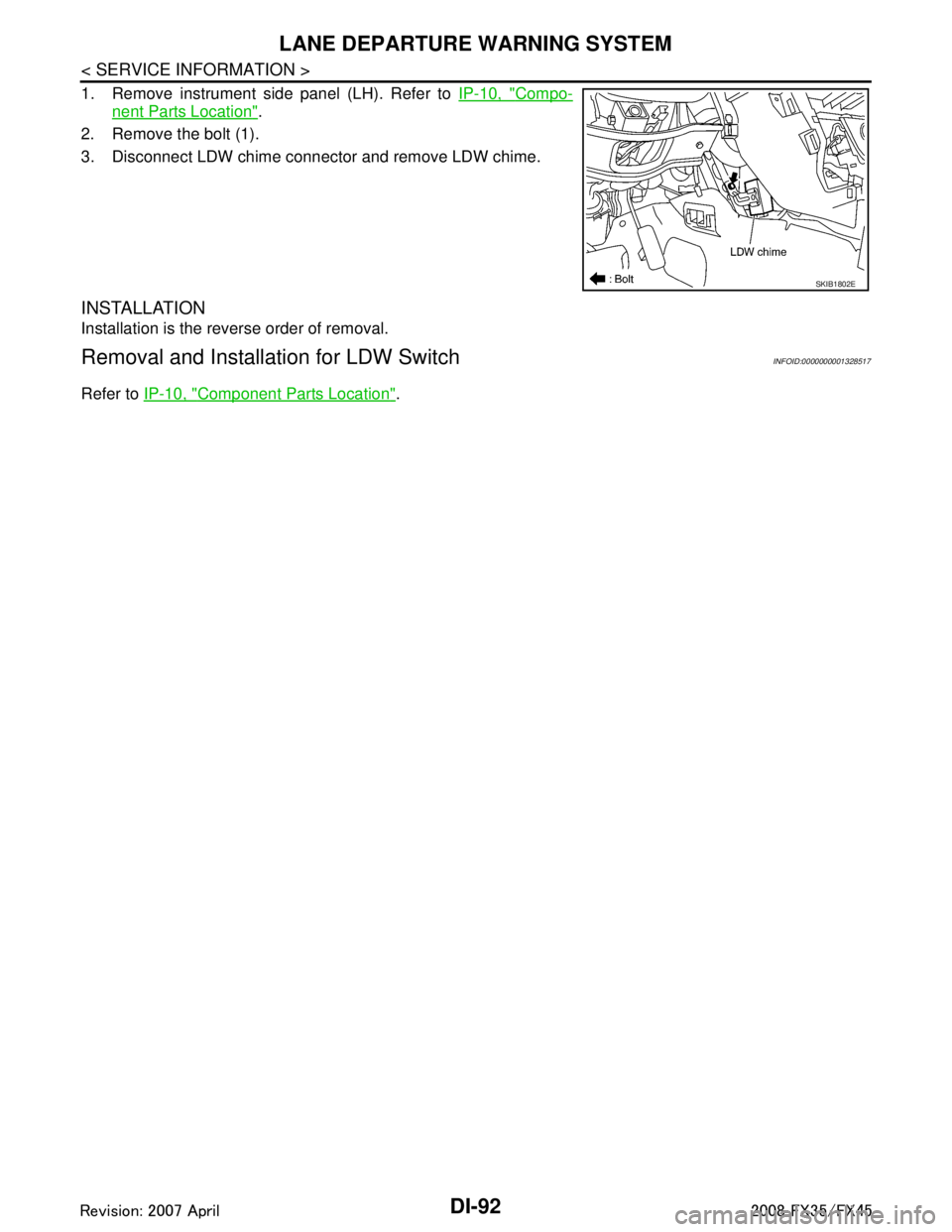
1. Remove instrument side panel (LH). Refer to IP-10, "Compo-
nent Parts Location".
2. Remove the bolt (1).
3. Disconnect LDW chime connector and remove LDW chime.
INSTALLATION
Installation is the reverse order of removal.
Removal and Installation for LDW SwitchINFOID:0000000001328517
Refer to IP-10, "Component Parts Location".
SKIB1802E
3AA93ABC3ACD3AC03ACA3AC03AC63AC53A913A773A893A873A873A8E3A773A983AC73AC93AC03AC3
3A893A873A873A8F3A773A9D3AAF3A8A3A8C3A863A9D3AAF3A8B3A8C
Page 1225 of 3924
CLOCKDI-99
< SERVICE INFORMATION >
C
DE
F
G H
I
J
L
M A
B
DI
N
O P
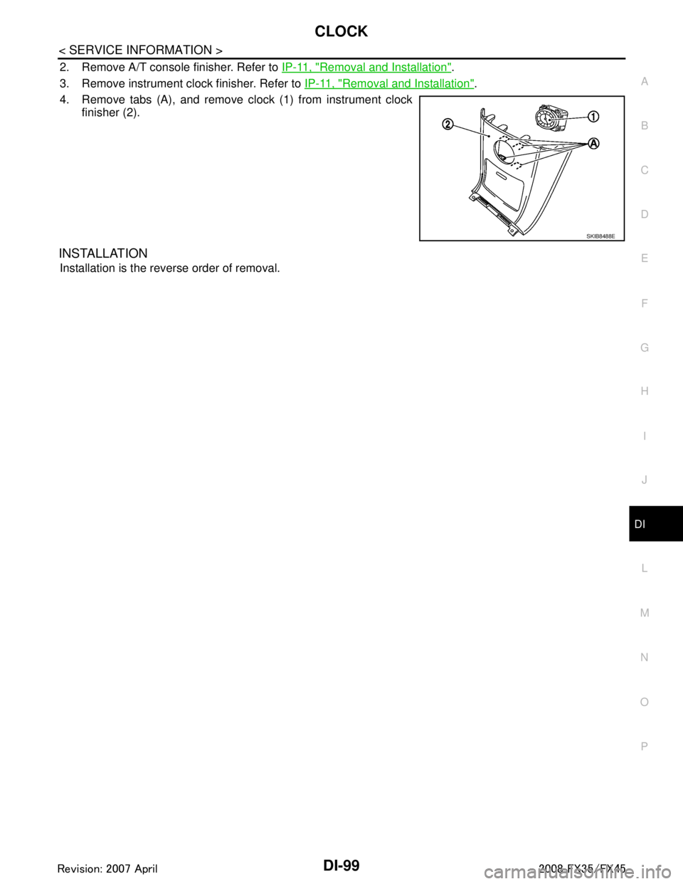
2. Remove A/T console finisher. Refer to IP-11, "Removal and Installation".
3. Remove instrument clock finisher. Refer to IP-11, "
Removal and Installation".
4. Remove tabs (A), and remove clock (1) from instrument clock finisher (2).
INSTALLATION
Installation is the reverse order of removal.
SKIB8488E
3AA93ABC3ACD3AC03ACA3AC03AC63AC53A913A773A893A873A873A8E3A773A983AC73AC93AC03AC3
3A893A873A873A8F3A773A9D3AAF3A8A3A8C3A863A9D3AAF3A8B3A8C
Page 1239 of 3924
REAR VIEW MONITORDI-113
< SERVICE INFORMATION >
C
DE
F
G H
I
J
L
M A
B
DI
N
O P
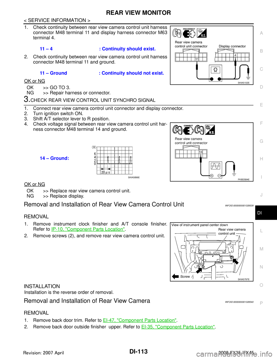
1. Check continuity between rear view camera control unit harness connector M48 terminal 11 and display harness connector M63
terminal 4.
2. Check continuity between rear view camera control unit harness connector M48 terminal 11 and ground.
OK or NG
OK >> GO TO 3.
NG >> Repair harness or connector.
3.CHECK REAR VIEW CONTROL UNIT SYNCHRO SIGNAL
1. Connect rear view camera control unit connector and display connector.
2. Turn ignition switch ON.
3. Shift A/T selector lever to R position.
4. Check voltage signal between rear view camera control unit har- ness connector M48 terminal 14 and ground.
OK or NG
OK >> Replace rear view camera control unit.
NG >> Replace display.
Removal and Installation of R ear View Camera Control UnitINFOID:0000000001328539
REMOVAL
1. Remove instrument clock finisher and A/T console finisher.
Refer to IP-10, "
Component Parts Location".
2. Remove screws (2), and remove rear view camera control unit.
INSTALLATION
Installation is the reverse order of removal.
Removal and Installation of Rear View CameraINFOID:0000000001328540
REMOVAL
1. Remove back door trim. Refer to EI-47, "Component Parts Location".
2. Remove back door outside finisher upper. Refer to EI-35, "
Component Parts Location".
11 – 4 : Continuity should exist.
11 – Ground : Continuity should not exist.
SKIA5102E
14 – Ground:
PKIB3584ESKIA5896E
SKIA5797E
3AA93ABC3ACD3AC03ACA3AC03AC63AC53A913A773A893A873A873A8E3A773A983AC73AC93AC03AC3
3A893A873A873A8F3A773A9D3AAF3A8A3A8C3A863A9D3AAF3A8B3A8C
Page 1294 of 3924
![INFINITI FX35 2008 Service Manual
EC-54
< SERVICE INFORMATION >[VQ35DE]
ON BOARD DIAGNOSTIC (OBD) SYSTEM
ON BOARD DIAGNO
STIC (OBD) SYSTEM
IntroductionINFOID:0000000001325914
The ECM has an on board diagnostic system, which detects INFINITI FX35 2008 Service Manual
EC-54
< SERVICE INFORMATION >[VQ35DE]
ON BOARD DIAGNOSTIC (OBD) SYSTEM
ON BOARD DIAGNO
STIC (OBD) SYSTEM
IntroductionINFOID:0000000001325914
The ECM has an on board diagnostic system, which detects](/manual-img/42/57017/w960_57017-1293.png)
EC-54
< SERVICE INFORMATION >[VQ35DE]
ON BOARD DIAGNOSTIC (OBD) SYSTEM
ON BOARD DIAGNO
STIC (OBD) SYSTEM
IntroductionINFOID:0000000001325914
The ECM has an on board diagnostic system, which detects malfunctions related to engine sensors or actua-
tors. The ECM also records various emission-related diagnostic information including:
The above information can be checked usi ng procedures listed in the table below.
×: Applicable —: Not applicable
*: When DTC and 1st trip DTC simultaneously appear on the display, they cannot be clearly distinguished from each other.
The malfunction indicator lamp (MIL) on the instrument panel lights up when the same malfunction is detected
in two consecutive trips (Two trip detection logic) , or when the ECM enters fail-safe mode. (Refer to EC-95,
"Fail-Safe Chart".)
Two Trip Detection LogicINFOID:0000000001325915
When a malfunction is detected for the 1st time, 1st trip DTC and 1st trip Freeze Frame data are stored in the
ECM memory. The MIL will not light up at this stage. <1st trip>
If the same malfunction is detected again during the next drive, the DTC and Freeze Frame data are stored in
the ECM memory, and the MIL lights up. The MIL lights up at the same time when the DTC is stored. <2nd
trip> The “trip” in the “Two Trip Detection Logic” m eans a driving mode in which self-diagnosis is performed
during vehicle operation. Specific on board diagnostic item s will cause the ECM to light up or blink the MIL,
and store DTC and Freeze Frame data, even in the 1st trip, as shown below.
× : Applicable —: Not applicable
When there is an open circuit on MIL circuit, the ECM c annot warn the driver by lighting up MIL when there is
malfunction on engine control system.
Emission-related diagnostic information Diagnostic service
Diagnostic Trouble Code (DTC) Service $03 of SAE J1979
Freeze Frame data Service $02 of SAE J1979
System Readiness Test (SRT) code Service $01 of SAE J1979
1st Trip Diagnostic Trouble Code (1st Trip DTC) Service $07 of SAE J1979
1st Trip Freeze Frame data
Test values and Test limits Service $06 of SAE J1979
Calibration ID Service $09 of SAE J1979
DTC 1st trip DTC Freeze
Frame data 1st trip Freeze
Frame data SRT code SRT status Test value
CONSULT-III ×× × × × × —
GST ×× × —×××
ECM ××*— — — ×—
Items MIL DTC 1st trip DTC
1st trip 2nd trip 1st trip
displaying 2nd trip
displaying 1st trip
displaying 2nd trip
display- ing
Blinking Lighting
up Blinking Lighting
up
Misfire (Possible three way catalyst
damage) — DTC: P0300 - P0306 is
being detected ×
———— — ×—
Misfire (Possible three way catalyst
damage) — DTC: P0300 - P0306 is
being detected ——
×—— ×——
One trip detection diagnoses (Re-
fer to EC-55, "
Emission-Related Di-
agnostic Information".) —
×—— ×———
Except above — — — ×— ×× —
3AA93ABC3ACD3AC03ACA3AC03AC63AC53A913A773A893A873A873A8E3A773A983AC73AC93AC03AC3
3A893A873A873A8F3A773A9D3AAF3A8A3A8C3A863A9D3AAF3A8B3A8C