2008 INFINITI FX35 check oil
[x] Cancel search: check oilPage 732 of 3924

BCS-12
< SERVICE INFORMATION >
BCM (BODY CONTROL MODULE)
ITEMS OF EACH PART
BCM can perform the following functions for each system.
NOTE:
CONSULT-III displays systems equipped in the vehicle.
×:Applicable
NOTE:
*1: Vehicle with remote keyless entry system display this item.
*2: Vehicle with Intelligent Key system display this item.
*3: This item is displayed, but does not function.
WORK SUPPORT
Display Item List
BCM Diagnostic test item Check item, diagnostic test mode Content
Inspection by part WORK SUPPORT Changes setting of each function.
SELF-DIAG RESULTS BCM performs self-diagnosis of CAN communication.
DATA MONITOR Displays the input data of BCM in real time.
CAN DIAG SUPPORT MNTR
The transmit/receive diagnosis result of CAN communication can be
read.
ACTIVE TEST Gives a drive signal to a load to check the operation.
ECU PART NUMBER ECM part number can be read.
CONFIGURATION (Not be used)
System and item CONSULT-III display Diagnostic test mode (Inspection by part)
WORK SUPPORT DATA MONITOR ACTIVE TEST
BCM BCM ×
Power door lock system DOOR LOCK ×××
Rear window defogger REAR DEFOGGER ××
Warning chime BUZZER ××
Room lamp timer INT LAMP ×××
Remote keyless entry system*
1MULTI REMOTE ENT ×××
Headlamp HEAD LAMP ×××
Wiper WIPER ×××
Turn signal lamp
Hazard lamp FLASHER
××
Blower fan switch signal
A/C switch signal AIR CONDITONER
×
Intelligent Key system*
2INTELLIGENT KEY ×
Combination switch COMB SW ×
NVIS IMMU ××
Room lamp battery saver BATTERY SAVER ×× ×
Trunk lid TRUNK*
3××
Vehicle security system THEFT ALM ×××
Retained power control RETAINED PWR ×××
Oil pressure swit ch SIGNAL BUFFER ××
Low tire pressure warning system AIR PRESSURE MONITOR ×××
Panic system PANIC ALARM ×
3AA93ABC3ACD3AC03ACA3AC03AC63AC53A913A773A893A873A873A8E3A773A983AC73AC93AC03AC3
3A893A873A873A8F3A773A9D3AAF3A8A3A8C3A863A9D3AAF3A8B3A8C
Page 986 of 3924

BR-2
< SERVICE INFORMATION >
PRECAUTIONS
SERVICE INFORMATION
PRECAUTIONS
Precaution for Supplemental Restraint System (SRS) "AIR BAG" and "SEAT BELT
PRE-TENSIONER"
INFOID:0000000001612918
The Supplemental Restraint System such as “A IR BAG” and “SEAT BELT PRE-TENSIONER”, used along
with a front seat belt, helps to reduce the risk or severi ty of injury to the driver and front passenger for certain
types of collision. This system includes seat belt switch inputs and dual stage front air bag modules. The SRS
system uses the seat belt switches to determine the front air bag deployment, and may only deploy one front
air bag, depending on the severity of a collision and w hether the front occupants are belted or unbelted.
Information necessary to service the system safely is included in the “SUPPLEMENTAL RESTRAINT SYS-
TEM” and “SEAT BELTS” of this Service Manual.
WARNING:
• To avoid rendering the SRS inopera tive, which could increase the risk of personal injury or death in
the event of a collision which would result in air bag inflation, all maintenance must be performed by
an authorized NISS AN/INFINITI dealer.
Improper maintenance, including in correct removal and installation of the SRS, can lead to personal
injury caused by unintent ional activation of the system. For re moval of Spiral Cable and Air Bag
Module, see the “SUPPLEMEN TAL RESTRAINT SYSTEM”.
Do not use electrical test equipmen t on any circuit related to the SRS unless instructed to in this
Service Manual. SRS wiring harnesses can be identi fied by yellow and/or orange harnesses or har-
ness connectors.
Precaution for Procedure without Cowl Top CoverINFOID:0000000001612920
When performing the procedure after removing cowl top cover, cover
the lower end of windshield with urethane, etc.
Precaution for Brake SystemINFOID:0000000001327604
Clean dust on front brake and rear brake with a vacuum dust collector. Do not blow with compressed air.
Recommended fluid is brake fluid “DOT 3”. MA-9, "
Fluids and Lubricants".
Do not reuse drained brake fluid.
Be careful not to splash brake fluid on painted areas.
To clean or wash all parts of master cylinder, disc brake caliper and wheel cylinder, use new brake fluid.
Do not use mineral oils such as gasoline or kerosene. They will ruin rubber parts of the hydraulic system.
Use a flare nut crowfoot and torque wrench when installing brake
tube.
When installing brake piping, be sure to check torque.
Before working, turn ignition switch OFF and disconnect connec- tors for ABS actuator and electric unit (control unit) or battery neg-
ative terminal.
Burnish the brake contact surfaces after refinishing or replacing drums or rotors, after replacing pads or linings, or if a soft pedal
occurs at very low mileage.
Refer to BR-23, "
Brake Burnishing Procedure" (Front disc brake),
BR-29, "
Brake Burnishing Procedure" (Rear disc brake).
WARNING:
Clean brake pads and shoes with a waste cl oth, then clean with a dust collector.
PIIB3706J
SBR686C
3AA93ABC3ACD3AC03ACA3AC03AC63AC53A913A773A893A873A873A8E3A773A983AC73AC93AC03AC3
3A893A873A873A8F3A773A9D3AAF3A8A3A8C3A863A9D3AAF3A8B3A8C
Page 1000 of 3924

BR-16
< SERVICE INFORMATION >
VACUUM LINES
VACUUM LINES
ComponentINFOID:0000000001327624
Removal and InstallationINFOID:0000000001327625
CAUTION:
Because vacuum hose contains a check valve, it must be installed in the correct direction. Refer to
the stamp or label to confirm co rrect installation. The brake booster will not ope rate normally if hose
is installed in the wrong direction.
Insert vacuum hose for at least 24 mm (0.94 in).
Do not use lubricating oil during assembly.
InspectionINFOID:0000000001327626
VISUAL INSPECTION
Check for improper assembly, damage and deterioration.
CHECK VALVE INSPECTION
1. Clamp 2. Vacuum hose 3. Clamp
4. Vacuum piping 5. Clamp 6. Engine direction indicator
7. Vacuum hose (Build in check valve) 8. Clamp 9. Brake booster
SFIA1134E
SBR225B
3AA93ABC3ACD3AC03ACA3AC03AC63AC53A913A773A893A873A873A8E3A773A983AC73AC93AC03AC3
3A893A873A873A8F3A773A9D3AAF3A8A3A8C3A863A9D3AAF3A8B3A8C
Page 1005 of 3924

FRONT DISC BRAKEBR-21
< SERVICE INFORMATION >
C
DE
G H
I
J
K L
M A
B
BR
N
O P
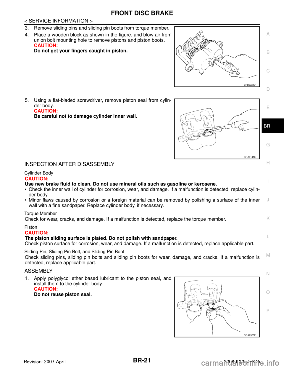
3. Remove sliding pins and sliding pin boots from torque member.
4. Place a wooden block as shown in the figure, and blow air from union bolt mounting hole to remove pistons and piston boots.
CAUTION:
Do not get your fingers caught in piston.
5. Using a flat-bladed screwdriver, remove piston seal from cylin- der body.
CAUTION:
Be careful not to damage cylinder inner wall.
INSPECTION AFTER DISASSEMBLY
Cylinder Body
CAUTION:
Use new brake fluid to clean. Do not use mi neral oils such as gasoline or kerosene.
Check the inner wall of cylinder for corrosion, wear, and damage. If a malfunction is detected, replace cylin-
der body.
Minor flaws caused by corrosion or a foreign material can be removed by polishing a surface of the inner wall with a fine sandpaper. Replace cylinder body, if necessary.
Torque Member
Check for wear, cracks, and damage. If a malfunc tion is detected, replace the torque member.
Piston
CAUTION:
The piston sliding surface is plated. Do not polish with sandpaper.
Check piston surface for corrosion, wear, and damage. If a malfunction is detected, replace applicable part.
Sliding Pin, Sliding Pin Bolt, and Sliding Pin Boot
Check sliding pins, sliding pin bolts and sliding pin boots for wear, damage, and cracks. If a malfunction is
detected, replace applicable part.
ASSEMBLY
1. Apply polyglycol ether based lubricant to the piston seal, and
install them to the cylinder body.
CAUTION:
Do not reuse piston seal.
BRB0032D
SFIA0141E
SFIA2920E
3AA93ABC3ACD3AC03ACA3AC03AC63AC53A913A773A893A873A873A8E3A773A983AC73AC93AC03AC3
3A893A873A873A8F3A773A9D3AAF3A8A3A8C3A863A9D3AAF3A8B3A8C
Page 1006 of 3924

BR-22
< SERVICE INFORMATION >
FRONT DISC BRAKE
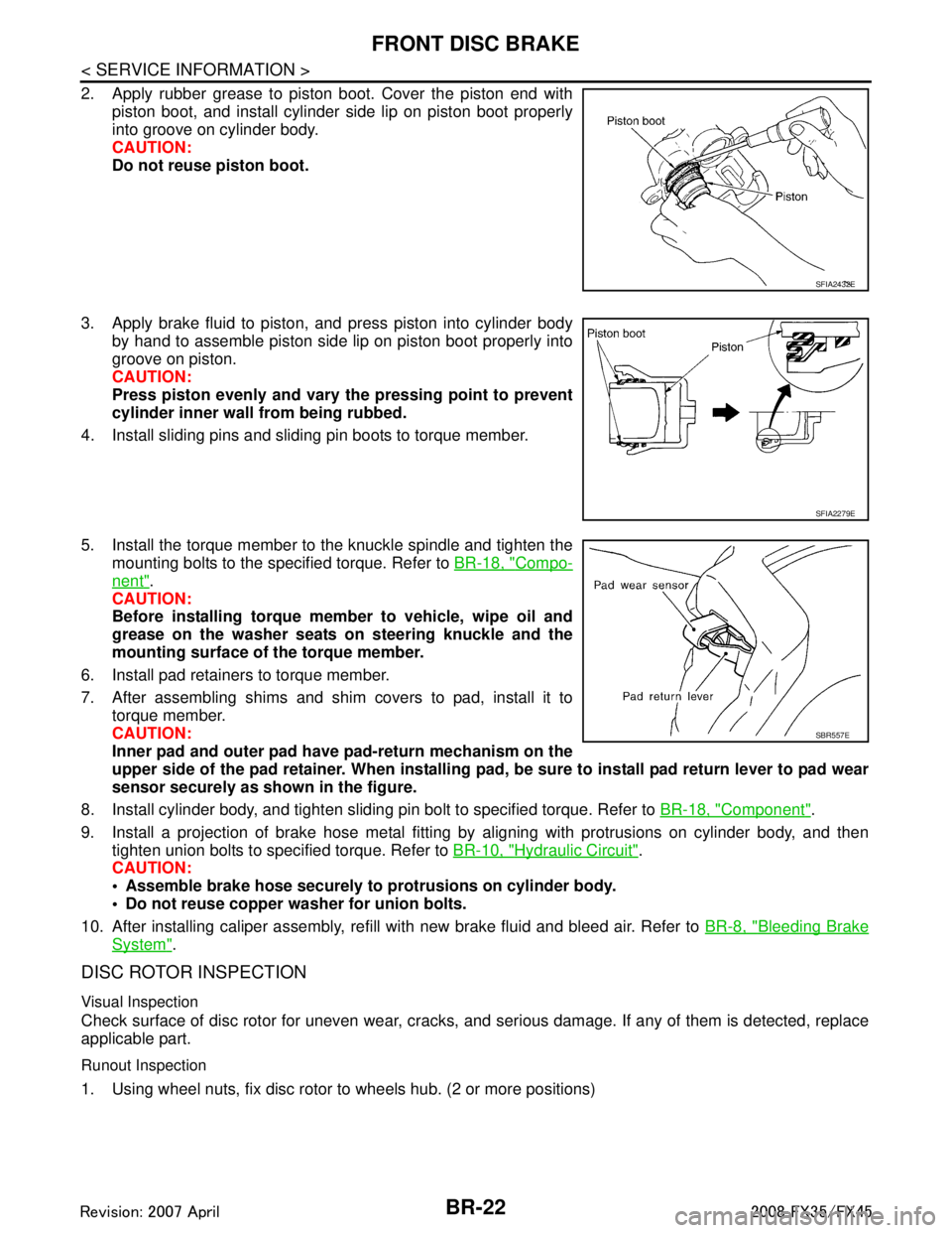
2. Apply rubber grease to piston boot. Cover the piston end withpiston boot, and install cylinder side lip on piston boot properly
into groove on cylinder body.
CAUTION:
Do not reuse piston boot.
3. Apply brake fluid to piston, and press piston into cylinder body by hand to assemble piston side lip on piston boot properly into
groove on piston.
CAUTION:
Press piston evenly and vary the pressing point to prevent
cylinder inner wall from being rubbed.
4. Install sliding pins and sliding pin boots to torque member.
5. Install the torque member to the knuckle spindle and tighten the mounting bolts to the specified torque. Refer to BR-18, "
Compo-
nent".
CAUTION:
Before installing torque member to vehicle, wipe oil and
grease on the washer seats on steering knuckle and the
mounting surface of the torque member.
6. Install pad retainers to torque member.
7. After assembling shims and shim covers to pad, install it to torque member.
CAUTION:
Inner pad and outer pad have pad-return mechanism on the
upper side of the pad retainer. When installing pad, be sure to install pad return lever to pad wear
sensor securely as shown in the figure.
8. Install cylinder body, and tighten sliding pin bolt to specified torque. Refer to BR-18, "
Component".
9. Install a projection of brake hose metal fitting by aligning with protrusions on cylinder body, and then tighten union bolts to specified torque. Refer to BR-10, "
Hydraulic Circuit".
CAUTION:
Assemble brake hose securely to protrusions on cylinder body.
Do not reuse copper washer for union bolts.
10. After installing caliper assembly, refill with new brake fluid and bleed air. Refer to BR-8, "
Bleeding Brake
System".
DISC ROTOR INSPECTION
Visual Inspection
Check surface of disc rotor for uneven wear, cracks, and serious damage. If any of them is detected, replace
applicable part.
Runout Inspection
1. Using wheel nuts, fix disc rotor to wheels hub. (2 or more positions)
SFIA2432E
SFIA2279E
SBR557E
3AA93ABC3ACD3AC03ACA3AC03AC63AC53A913A773A893A873A873A8E3A773A983AC73AC93AC03AC3
3A893A873A873A8F3A773A9D3AAF3A8A3A8C3A863A9D3AAF3A8B3A8C
Page 1011 of 3924

REAR DISC BRAKEBR-27
< SERVICE INFORMATION >
C
DE
G H
I
J
K L
M A
B
BR
N
O P
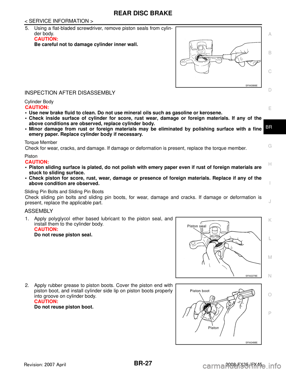
5. Using a flat-bladed screwdriver, remove piston seals from cylin- der body.
CAUTION:
Be careful not to damage cylinder inner wall.
INSPECTION AFTER DISASSEMBLY
Cylinder Body
CAUTION:
Use new brake fluid to clean. Do not use mine ral oils such as gasoline or kerosene.
Check inside surface of cylinder for score, rust wear , damage or foreign materials. If any of the
above conditions are obser ved, replace cylinder body.
Minor damage from rust or foreign materials m ay be eliminated by polishing surface with a fine
emery paper. Replace cylinder body if necessary.
Torque Member
Check for wear, cracks, and damage. If damage or def ormation is present, replace the torque member.
Piston
CAUTION:
Piston sliding surface is plated, do not polish with emery paper even if rust of foreign materials are
stuck to sliding surface.
Check piston for score, rust, wear , damage or presence of foreign materials. Replace if any of the
above condition are observed.
Sliding Pin Bolts and Sliding Pin Boots
Check sliding pin bolts and sliding pin boots, for wear, damage and cracks. If damage or deformation is
present, replace the applicable part.
ASSEMBLY
1. Apply polyglycol ether based lubricant to the piston seal, and install them to the cylinder body.
CAUTION:
Do not reuse piston seal.
2. Apply rubber grease to piston boots. Cover the piston end with piston boot, and install cylinder side lip on piston boots properly
into groove on cylinder body.
CAUTION:
Do not reuse piston boot.
SFIA0999E
SFIA2278E
SFIA2498E
3AA93ABC3ACD3AC03ACA3AC03AC63AC53A913A773A893A873A873A8E3A773A983AC73AC93AC03AC3
3A893A873A873A8F3A773A9D3AAF3A8A3A8C3A863A9D3AAF3A8B3A8C
Page 1020 of 3924
![INFINITI FX35 2008 Service Manual
PRECAUTIONSBRC-5
< SERVICE INFORMATION > [VDC/TCS/ABS]
C
D
E
G H
I
J
K L
M A
B
BRC
N
O P
PRECAUTIONS
Precaution for Supplemental Restraint System (SRS) "AIR BAG" and "SEAT BELT
PRE-TENSIONER"
INFOI INFINITI FX35 2008 Service Manual
PRECAUTIONSBRC-5
< SERVICE INFORMATION > [VDC/TCS/ABS]
C
D
E
G H
I
J
K L
M A
B
BRC
N
O P
PRECAUTIONS
Precaution for Supplemental Restraint System (SRS) "AIR BAG" and "SEAT BELT
PRE-TENSIONER"
INFOI](/manual-img/42/57017/w960_57017-1019.png)
PRECAUTIONSBRC-5
< SERVICE INFORMATION > [VDC/TCS/ABS]
C
D
E
G H
I
J
K L
M A
B
BRC
N
O P
PRECAUTIONS
Precaution for Supplemental Restraint System (SRS) "AIR BAG" and "SEAT BELT
PRE-TENSIONER"
INFOID:0000000001612923
The Supplemental Restraint System such as “A IR BAG” and “SEAT BELT PRE-TENSIONER”, used along
with a front seat belt, helps to reduce the risk or severi ty of injury to the driver and front passenger for certain
types of collision. This system includes seat belt switch inputs and dual stage front air bag modules. The SRS
system uses the seat belt switches to determine the front air bag deployment, and may only deploy one front
air bag, depending on the severity of a collision and whether the front occupants are belted or unbelted.
Information necessary to service the system safely is included in the “SUPPLEMENTAL RESTRAINT SYS-
TEM” and “SEAT BELTS” of this Service Manual.
WARNING:
• To avoid rendering the SRS inoper ative, which could increase the risk of personal injury or death in
the event of a collision which would result in air bag inflation, all maintenance must be performed by
an authorized NISSAN/INFINITI dealer.
Improper maintenance, including in correct removal and installation of the SRS, can lead to personal
injury caused by unintentional act ivation of the system. For removal of Spiral Cable and Air Bag
Module, see the “SUPPLEMEN TAL RESTRAINT SYSTEM”.
Do not use electrical test equipm ent on any circuit related to the SRS unless instructed to in this
Service Manual. SRS wiring harnesses can be identi fied by yellow and/or orange harnesses or har-
ness connectors.
Precaution for Brake SystemINFOID:0000000001327654
Recommended fluid is brake fluid “DOT 3”. Refer to MA-9.
Do not reuse drained brake fluid.
Be careful not to splash brake fluid on painted areas such as body. If brake fluid is splashed, wipe it off and flush area with water immediately.
Do not use mineral oils such as gasoline or kerosene to clean. They will ruin rubber parts and cause improper operation.
Using a flare nut crowfoot and torque wrench, securely tighten brake tube flare nuts.
Brake system is an important safe ty part. If a brake fluid leak is
detected, always disassemble the affected part. If a malfunction is
detected, replace part with a new one.
Before working, turn ignition switch OFF and disconnect electrical
connectors of ABS actuator and elec tric unit (control unit) or bat-
tery negative terminal.
When installing brake piping, be sure to check torque.
WARNING:
Clean brake pads and shoes with a waste cloth, then wipe with
a dust collector.
Precaution for Brake ControlINFOID:0000000001327655
During VDC/TCS/ABS operation, brake pedal lightly vi brates and a mechanical noise may be heard. This is
normal.
Just after starting vehicle after turning ignition switch ON, brake pedal may vibrate or motor operating noise
may be heard from engine room. This is a normal status of operation check.
Stopping distance may be longer than that of vehicles without ABS when vehicle drives on rough, gravel, or
snow-covered (fresh, deep snow) roads.
When an error is indicated by ABS or another warning lamp, collect all necessary information from customer
(what symptoms are present under what conditions) and check for simple causes before starting diagnostic
servicing. Besides electrical system inspection, c heck booster operation, brake fluid level, and fluid leaks.
If tire size and type are used in an improper combinat ion, or brake pads are not Genuine NISSAN parts,
stopping distance or steering stability may deteriorate.
If there is a radio, antenna, or antenna lead-in wire (including wiring) near control module, VDC/TCS/ABS
function may have a malfunction or error.
If aftermarket parts (car stereo, CD player, etc.) have been installed, check for incidents such as harness
pinches, open circuits, and improper wiring.
SBR686C
3AA93ABC3ACD3AC03ACA3AC03AC63AC53A913A773A893A873A873A8E3A773A983AC73AC93AC03AC3
3A893A873A873A8F3A773A9D3AAF3A8A3A8C3A863A9D3AAF3A8B3A8C
Page 1085 of 3924
![INFINITI FX35 2008 Service Manual
CO-14
< SERVICE INFORMATION >[VQ35DE]
RADIATOR
4. Remove reservoir tank and reservoir tank bracket.
5. Disconnect A/T fluid cooler hoses from radiator.
Install blind plug to avoid leakage of A/T fl INFINITI FX35 2008 Service Manual
CO-14
< SERVICE INFORMATION >[VQ35DE]
RADIATOR
4. Remove reservoir tank and reservoir tank bracket.
5. Disconnect A/T fluid cooler hoses from radiator.
Install blind plug to avoid leakage of A/T fl](/manual-img/42/57017/w960_57017-1084.png)
CO-14
< SERVICE INFORMATION >[VQ35DE]
RADIATOR
4. Remove reservoir tank and reservoir tank bracket.
5. Disconnect A/T fluid cooler hoses from radiator.
Install blind plug to avoid leakage of A/T fluid.
6. Removal radiator hoses (upper and lower) and reservoir tank hose. CAUTION:
Be careful not to allow engine coolant to contact drive belts.
7. Remove radiator cooling fan assembly. Refer to CO-20, "
Component".
8. Rotate two radiator upper mount brackets 90 degrees in the direction shown in the figure, and remove them.
9. Lift up and remove radiator. CAUTION:
Do not damage or scratch A/C condenser and radiator core
when removing.
INSTALLATION
Installation is the reverse order of removal.
INSPECTION AFTER INSTALLATION
Check for leaks of engine coolant using the radiator cap tester adapter (commercial service tool) and the
radiator cap tester (commercial service tool). Refer to CO-10, "
Inspection".
Start and warm up the engine. Visually make sure t hat there is no leaks of engine coolant and A/T fluid.
Checking Radiator CapINFOID:0000000001325849
Check valve seat of radiator cap.
- Check if valve seat is swollen to the extent that the edge of the
plunger cannot be seen when watching it vertically from the top.
- Check if valve seat has no soil and damage.
SBIA0447E
SBIA0448E
PBIC2816E
3AA93ABC3ACD3AC03ACA3AC03AC63AC53A913A773A893A873A873A8E3A773A983AC73AC93AC03AC3
3A893A873A873A8F3A773A9D3AAF3A8A3A8C3A863A9D3AAF3A8B3A8C