2008 INFINITI FX35 check oil
[x] Cancel search: check oilPage 1095 of 3924
![INFINITI FX35 2008 Service Manual
CO-24
< SERVICE INFORMATION >[VQ35DE]
WATER PUMP
b. Screw M8 bolts [pitch: 1.25 mm (0.0492 in) length: approx. 50
mm (1.97 in)] into water pumps upper and lower mounting bolt
holes until they reach t INFINITI FX35 2008 Service Manual
CO-24
< SERVICE INFORMATION >[VQ35DE]
WATER PUMP
b. Screw M8 bolts [pitch: 1.25 mm (0.0492 in) length: approx. 50
mm (1.97 in)] into water pumps upper and lower mounting bolt
holes until they reach t](/manual-img/42/57017/w960_57017-1094.png)
CO-24
< SERVICE INFORMATION >[VQ35DE]
WATER PUMP
b. Screw M8 bolts [pitch: 1.25 mm (0.0492 in) length: approx. 50
mm (1.97 in)] into water pumps upper and lower mounting bolt
holes until they reach timing chain case. Then, alternately
tighten each bolt for a half turn, and pull out water pump.
CAUTION:
Pull straight out while pr eventing vane from contacting
socket in installation area.
Remove water pump without causing sprocket to contact timing chain.
c. Remove M8 bolts and O-rings from water pump. CAUTION:
Do not disassemble water pump.
INSPECTION AFTER REMOVAL
Check for badly rusted or corroded water pump body assembly.
Check for rough operation due to excessive end play.
If anything is found, replace water pump.
INSTALLATION
1. Install new O-rings to water pump. Apply engine oil and engine coolant to O-rings as shown in the
figure.
Locate O-ring with white paint mark to engine front side.
2. Install water pump. CAUTION:
Do not allow cylinder block to nip O-rings when installing
water pump.
Make sure timing chain and water pump sprocket are engaged.
Insert water pump by tightening mounting bolts alternately and evenly.
3. Install timing chain tensioner (primary) as follows:
JLC357B
SLC943A
PBIC1397E
PBIC1058E
3AA93ABC3ACD3AC03ACA3AC03AC63AC53A913A773A893A873A873A8E3A773A983AC73AC93AC03AC3
3A893A873A873A8F3A773A9D3AAF3A8A3A8C3A863A9D3AAF3A8B3A8C
Page 1098 of 3924
![INFINITI FX35 2008 Service Manual
WATER INLET AND THERMOSTAT ASSEMBLYCO-27
< SERVICE INFORMATION > [VQ35DE]
C
D
E
F
G H
I
J
K L
M A
CO
NP
O
WATER INLET AND THERMOSTAT ASSEMBLY
ComponentINFOID:0000000001325858
Refer to
GI-8, "Compo INFINITI FX35 2008 Service Manual
WATER INLET AND THERMOSTAT ASSEMBLYCO-27
< SERVICE INFORMATION > [VQ35DE]
C
D
E
F
G H
I
J
K L
M A
CO
NP
O
WATER INLET AND THERMOSTAT ASSEMBLY
ComponentINFOID:0000000001325858
Refer to
GI-8, "Compo](/manual-img/42/57017/w960_57017-1097.png)
WATER INLET AND THERMOSTAT ASSEMBLYCO-27
< SERVICE INFORMATION > [VQ35DE]
C
D
E
F
G H
I
J
K L
M A
CO
NP
O
WATER INLET AND THERMOSTAT ASSEMBLY
ComponentINFOID:0000000001325858
Refer to
GI-8, "Component" for symbols in the figure.
Removal and InstallationINFOID:0000000001325859
REMOVAL
1. Remove front engine undercover using power tool.
2. Drain engine coolant from radiator drain plug at the bottom of radiator, and from water drain plug at the
front of cylinder block. Refer to CO-10, "
Changing Engine Coolant" and CO-22, "Component".
CAUTION:
Perform this step when the engine is cold.
Do not spill engine coolant on drive belts.
3. Remove air duct (inlet). Refer to EM-17, "
Component".
4. Disconnect radiator hose (lower) and oil cooler wate r hose from water inlet and thermostat assembly.
5. Remove water inlet and thermostat assembly. CAUTION:
Do not disassemble water inle t and thermostat assembly.
Replace them as a unit, if necessary.
INSPECTION AFTER REMOVAL
1. Check valve seating condition at ordinary r oom temperatures. It should seat tightly.
1. Water inlet and thermostat assembly 2. Gasket
PBIC5002E
SLC962AB
3AA93ABC3ACD3AC03ACA3AC03AC63AC53A913A773A893A873A873A8E3A773A983AC73AC93AC03AC3
3A893A873A873A8F3A773A9D3AAF3A8A3A8C3A863A9D3AAF3A8B3A8C
Page 1113 of 3924
![INFINITI FX35 2008 Service Manual
CO-42
< SERVICE INFORMATION >[VK45DE]
RADIATOR
11. Lift up and remove radiator.
CAUTION:
Do not damage or scratch A/C condenser and radiator core
when removing.
INSTALLATION
Install in the reverse or INFINITI FX35 2008 Service Manual
CO-42
< SERVICE INFORMATION >[VK45DE]
RADIATOR
11. Lift up and remove radiator.
CAUTION:
Do not damage or scratch A/C condenser and radiator core
when removing.
INSTALLATION
Install in the reverse or](/manual-img/42/57017/w960_57017-1112.png)
CO-42
< SERVICE INFORMATION >[VK45DE]
RADIATOR
11. Lift up and remove radiator.
CAUTION:
Do not damage or scratch A/C condenser and radiator core
when removing.
INSTALLATION
Install in the reverse order of removal.
INSPECTION AFTER INSTALLATION
Check for leaks of engine coolant using radiator cap tester adapter (commercial service tool) and radiator
cap tester (commercial service tool). Refer to CO-37, "
Inspection".
Start and warm up engine. Visually Check if t here is no leaks of engine coolant and A/T fluid.
Checking Radiator CapINFOID:0000000001325873
Check valve seat of radiator cap.
- Check if valve seat is swollen to the extent that the edge of the
plunger cannot be seen when watching it vertically from the top.
- Check if valve seat has no soil and damage.
Pull negative-pressure valve to open it, and make sure that it close
completely when released.
- Make sure that there is no dirt or damage on the valve seat of radi-
ator cap negative-pressure valve.
- Make sure that there are no unusualness in the opening and clos- ing conditions of negative-pressure valve.
Check radiator cap relief pressure.
- When connecting radiator cap to the radiator cap tester adapter (commercial service tool) (B) and t he radiator cap tester (commer-
cial service tool) (A), apply engine c oolant to the cap seal surface.
Replace radiator cap if there is an unusualness.
PBIC1536E
PBIC2816E
SMA967B
Standard : 78 - 98 kPa (0.8 - 1.0 kg/cm2, 11 - 14 psi)
Limit : 59 kPa (0.6 kg/cm
2, 9 psi)
PBIC5122J
3AA93ABC3ACD3AC03ACA3AC03AC63AC53A913A773A893A873A873A8E3A773A983AC73AC93AC03AC3
3A893A873A873A8F3A773A9D3AAF3A8A3A8C3A863A9D3AAF3A8B3A8C
Page 1134 of 3924

DI-8
< SERVICE INFORMATION >
COMBINATION METERS
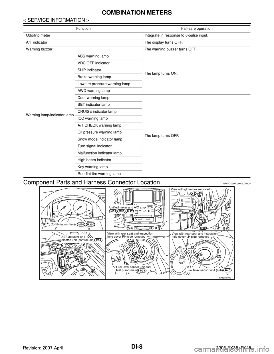
Component Parts and Harn ess Connector Location
INFOID:0000000001328434
Odo/trip meter Integrate in response to 8-pulse input.
A/T indicator The display turns OFF.
Warning buzzer The warning buzzer turns OFF.
Warning lamp/indicator lamp ABS warning lamp
The lamp turns ON.
VDC OFF indicator
SLIP indicator
Brake warning lamp
Low tire pressure warning lamp
AWD warning lamp
Door warning lamp
The lamp turns OFF.
SET indicator lamp
CRUISE indicator lamp
ICC warning lamp
A/T CHECK warning lamp
Oil pressure warning lamp
Snow mode indicator lamp
Turn signal indicator
Malfunction indicator lamp
High beam indicator
Key warning lamp
Run-flat tire warning lamp
Function Fail-safe operation
SKIB8474E
3AA93ABC3ACD3AC03ACA3AC03AC63AC53A913A773A893A873A873A8E3A773A983AC73AC93AC03AC3
3A893A873A873A8F3A773A9D3AAF3A8A3A8C3A863A9D3AAF3A8B3A8C
Page 1152 of 3924

DI-26
< SERVICE INFORMATION >
UNIFIED METER AND A/C AMP
UNIFIED METER AND A/C AMP
System DescriptionINFOID:0000000001328456
For the unified meter and A/C amp., the signal required for controlling the combination meter are integrated
in the A/C auto amp.
The unified meter and A/C amp. corresponds to a CONS ULT-III function (self-diagnosis results, CAN diag-
nosis support monitor, data monitor).
COMBINATION METER CONTROL FUNCTION
Unified meter and A/C amp. receives necessary information for combination meter from each unit by CAN communication.
Unified meter and A/C amp. transmits a signals with communication line (TX, RX) between unified meter and A/C amp. and combination meter.
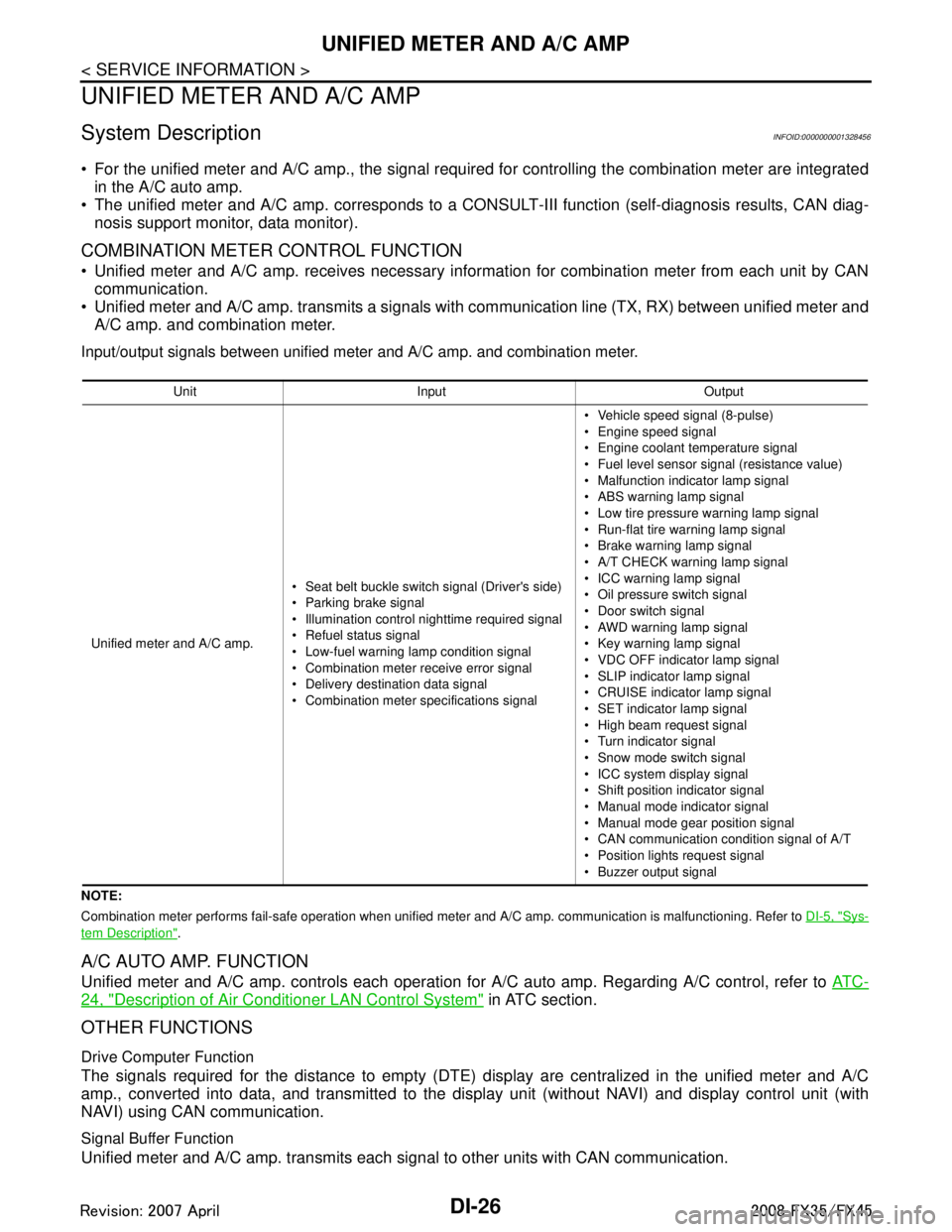
Input/output signals between unified meter and A/C amp. and combination meter.
NOTE:
Combination meter performs fail-safe operation when unified meter and A/C amp. communication is malfunctioning. Refer to DI-5, "
Sys-
tem Description".
A/C AUTO AMP. FUNCTION
Unified meter and A/C amp. controls each operation for A/C auto amp. Regarding A/C control, refer to AT C -
24, "Description of Air Conditioner LAN Control System" in ATC section.
OTHER FUNCTIONS
Drive Computer Function
The signals required for the distance to empty (DTE) display are centralized in the unified meter and A/C
amp., converted into data, and transmitted to the disp lay unit (without NAVI) and display control unit (with
NAVI) using CAN communication.
Signal Buffer Function
Unified meter and A/C amp. transmits each signal to other units with CAN communication.
Unit Input Output
Unified meter and A/C amp. Seat belt buckle switch signal (Driver's side)
Parking brake signal
Illumination control nighttime required signal
Refuel status signal
Low-fuel warning lamp condition signal
Combination meter receive error signal
Delivery destination data signal
Combination meter specifications signal Vehicle speed signal (8-pulse)
Engine speed signal
Engine coolant temperature signal
Fuel level sensor signal (resistance value)
Malfunction indicator lamp signal
ABS warning lamp signal
Low tire pressure warning lamp signal
Run-flat tire wa
rning lamp signal
Brake warning lamp signal
A/T CHECK warning lamp signal
ICC warning lamp signal
Oil pressure switch signal
Door switch signal
AWD warning lamp signal
Key warning lamp signal
VDC OFF indicator lamp signal
SLIP indicator lamp signal
CRUISE indicator lamp signal
SET indicator lamp signal
High beam request signal
Turn indicator signal
Snow mode switch signal
ICC system display signal
Shift position indicator signal
Manual mode indicator signal
Manual mode gear position signal
CAN communication condition signal of A/T
Position lights request signal
Buzzer output signal
3AA93ABC3ACD3AC03ACA3AC03AC63AC53A913A773A893A873A873A8E3A773A983AC73AC93AC03AC3
3A893A873A873A8F3A773A9D3AAF3A8A3A8C3A863A9D3AAF3A8B3A8C
Page 1155 of 3924

UNIFIED METER AND A/C AMPDI-29
< SERVICE INFORMATION >
C
DE
F
G H
I
J
L
M A
B
DI
N
O P
NOTE:
Monitored item that does not match the vehicle is deleted from the display automatically.
*1: It dose not change when fastening or unfastening the passenger seat belt.
*2: Monitor keeps indicating “off” when brake warning lamp is on by the parking brake operation or low brake fluid level.
Power Supply and Gro und Circuit InspectionINFOID:0000000001328459
1.CHECK FUSE
Check for blown unified meter and A/C amp. fuses.
OK or NG
OK >> GO TO 2.
NG >> Be sure to eliminate cause of malfunction before installing new fuse. Refer to PG-3, "
Schematic".
2.CHECK POWER SUPPLY CIRCUIT
OIL W/L [On/Off] X Indicates [On/Off] condition of oil pressure warning lamp.
VDC/TCS IND [On/Off] X Indicates [On/Off] condition of VDC OFF indicator lamp.
ABS W/L [On/Off] X Indicates [On/Off] condition of ABS warning lamp.
SLIP IND [On/Off] X Indicates [On/Off] condition of SLIP indicator lamp.
BRAKE W/L [On/Off]
*2X Indicates [On/Off] condition of brake warning lamp.
KEY G W/L [On/Off] X Indicates [On/Off] condition of key warning lamp (green).
KEY R W/L [On/Off] X Indicates [On/Off] condition of key warning lamp (red).
KEY KNOB W/L [On/Off] X Indicates [On/Off] condition of key knob warning lamp.
M RANGE SW [On/Off] X X Indicates [On/Off] condition of manual mode range switch.
NM RANGE SW [On/Off] X X Indicates [On/Off] condition of except for manual mode range
switch.
AT SFT UP SW [On/Off] X X Indicates [On/Off] condition of A/T shift-up switch.
AT SFT DWN SW [On/Off] X X Indicates [On/Off] condition of A/T shift-down switch.
BRAKE SW [On/Off] X Indicates [On/Off] condition of brake switch (stop lamp switch).
AT-M IND [On/Off] X X Indicates [On/Off] condition of A/T manual mode indicator.
AT-M GEAR [5-1] X X Indicates [5-1] condition of A/T manual mode gear position.
P RANGE IND [On/Off] X X Indicates [On/Off] condition of A/T shift P range indicator.
R RANGE IND [On/Off] X X Indicates [On/Off] condition of A/T shift R range indicator.
N RANGE IND [On/Off] X X Indicates [On/Off] condition of A/T shift N range indicator.
D RANGE IND [On/Off] X X Indicates [On/Off] condition of A/T shift D range indicator.
AT CHECK W/L X Indicates [On/Off] cond ition of AT CHECK warning lamp.
CRUISE IND [On/Off] X Indicates [On/Off] condition of CRUISE indicator lamp.
SET IND [On/Off] X Indicates [On/Off] condition of SET indicator lamp.
CRUISE W/L [On/Off] X Indicates [On/Of f] condition of ICC warning lamp.
4WD LOCK SW [On/Off] X This item is not used for this model. “off” is always displayed.
4WD LOCK IND [On/Off] X This item is not used for this model. “off” is always displayed.
4WD W/L [On/Off] X Indicates [On/Off] condition of AWD warning lamp.
RR COMB STATE [OK/NG] X Indicates [OK/NG] condition of rear combination lamp circuit. Display item [Unit]
MAIN
SIGNALS SELECTION
FROM MENU Contents
Power source Fuse No.
Battery power supply 19 ACC power supply 10, 11
Ignition power supply 12
3AA93ABC3ACD3AC03ACA3AC03AC63AC53A913A773A893A873A873A8E3A773A983AC73AC93AC03AC3
3A893A873A873A8F3A773A9D3AAF3A8A3A8C3A863A9D3AAF3A8B3A8C
Page 1169 of 3924

WARNING LAMPSDI-43
< SERVICE INFORMATION >
C
DE
F
G H
I
J
L
M A
B
DI
N
O P
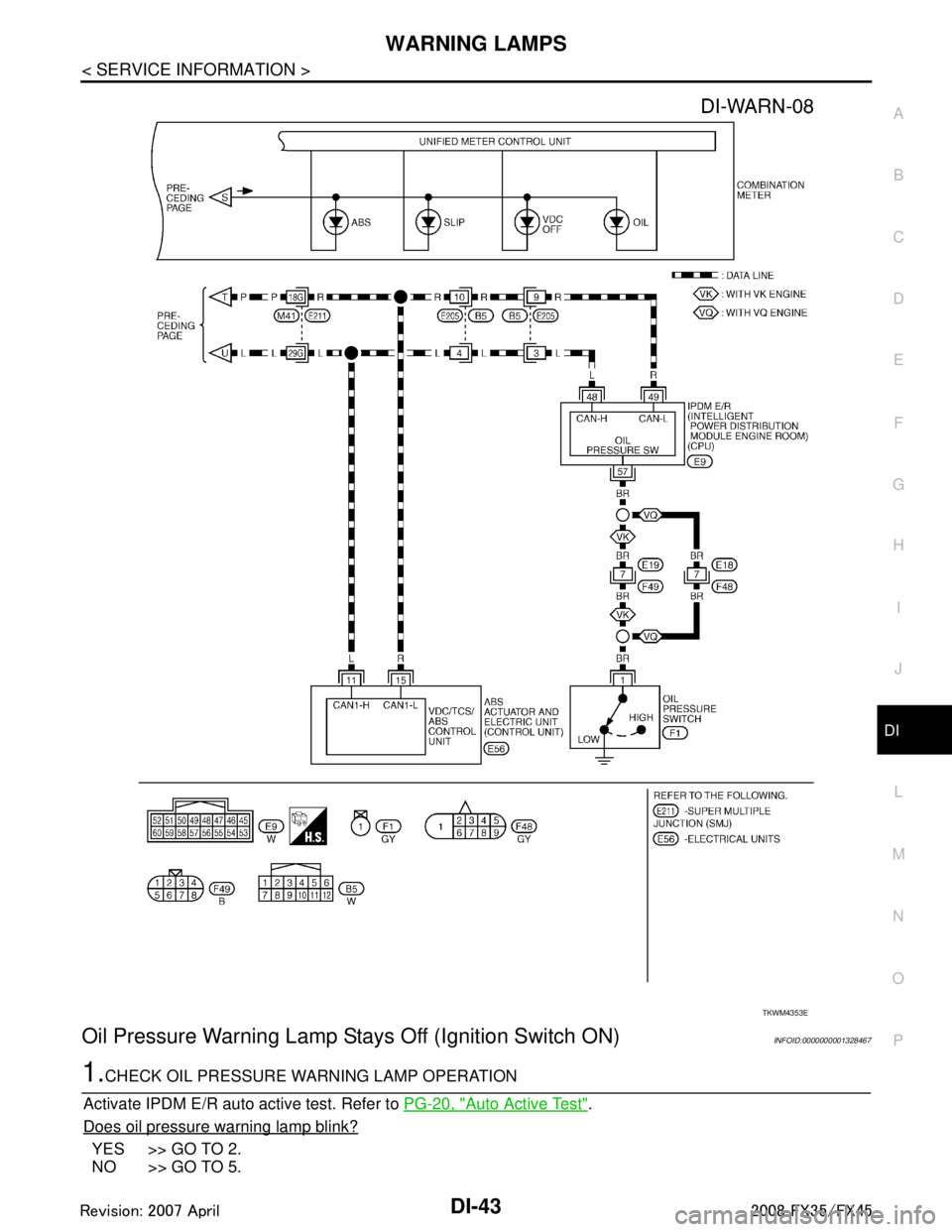
Oil Pressure Warning Lamp Stay s Off (Ignition Switch ON)INFOID:0000000001328467
1.CHECK OIL PRESSURE WARNING LAMP OPERATION
Activate IPDM E/R auto active test. Refer to PG-20, "
Auto Active Test".
Does oil pressure warning lamp blink?
YES >> GO TO 2.
NO >> GO TO 5.
TKWM4353E
3AA93ABC3ACD3AC03ACA3AC03AC63AC53A913A773A893A873A873A8E3A773A983AC73AC93AC03AC3
3A893A873A873A8F3A773A9D3AAF3A8A3A8C3A863A9D3AAF3A8B3A8C
Page 1170 of 3924

DI-44
< SERVICE INFORMATION >
WARNING LAMPS
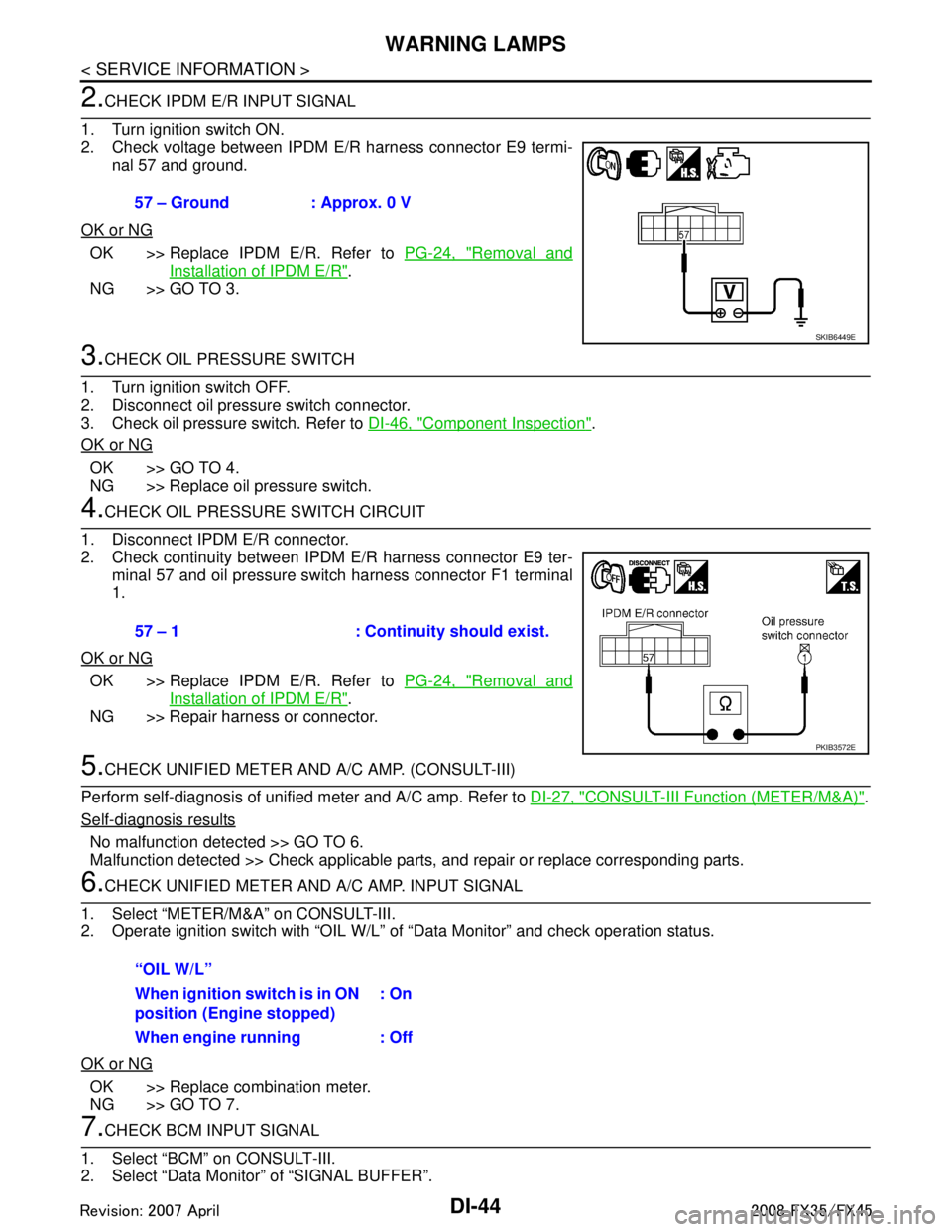
2.CHECK IPDM E/R INPUT SIGNAL
1. Turn ignition switch ON.
2. Check voltage between IPDM E/R harness connector E9 termi- nal 57 and ground.
OK or NG
OK >> Replace IPDM E/R. Refer to PG-24, "Removal and
Installation of IPDM E/R".
NG >> GO TO 3.
3.CHECK OIL PRESSURE SWITCH
1. Turn ignition switch OFF.
2. Disconnect oil pressure switch connector.
3. Check oil pressure switch. Refer to DI-46, "
Component Inspection".
OK or NG
OK >> GO TO 4.
NG >> Replace oil pressure switch.
4.CHECK OIL PRESSURE SWITCH CIRCUIT
1. Disconnect IPDM E/R connector.
2. Check continuity between IPDM E/R harness connector E9 ter- minal 57 and oil pressure switch harness connector F1 terminal
1.
OK or NG
OK >> Replace IPDM E/R. Refer to PG-24, "Removal and
Installation of IPDM E/R".
NG >> Repair harness or connector.
5.CHECK UNIFIED METER AND A/C AMP. (CONSULT-III)
Perform self-diagnosis of unified meter and A/C amp. Refer to DI-27, "
CONSULT-III Function (METER/M&A)".
Self-diagnosis results
No malfunction detected >> GO TO 6.
Malfunction detected >> Check applicable parts, and repair or replace corresponding parts.
6.CHECK UNIFIED METER AND A/C AMP. INPUT SIGNAL
1. Select “METER/M&A” on CONSULT-III.
2. Operate ignition switch with “OIL W/L” of “Data Monitor” and check operation status.
OK or NG
OK >> Replace combination meter.
NG >> GO TO 7.
7.CHECK BCM INPUT SIGNAL
1. Select “BCM” on CONSULT-III.
2. Select “Data Monitor” of “SIGNAL BUFFER”. 57 – Ground : Approx. 0 V
SKIB6449E
57 – 1 : Continuity should exist.
PKIB3572E
“OIL W/L”
When ignition switch is in ON
position (Engine stopped)
: On
When engine running : Off
3AA93ABC3ACD3AC03ACA3AC03AC63AC53A913A773A893A873A873A8E3A773A983AC73AC93AC03AC3
3A893A873A873A8F3A773A9D3AAF3A8A3A8C3A863A9D3AAF3A8B3A8C