2008 INFINITI FX35 tow
[x] Cancel search: towPage 3487 of 3924
PS-32
< SERVICE INFORMATION >
POWER STEERING OIL PUMP
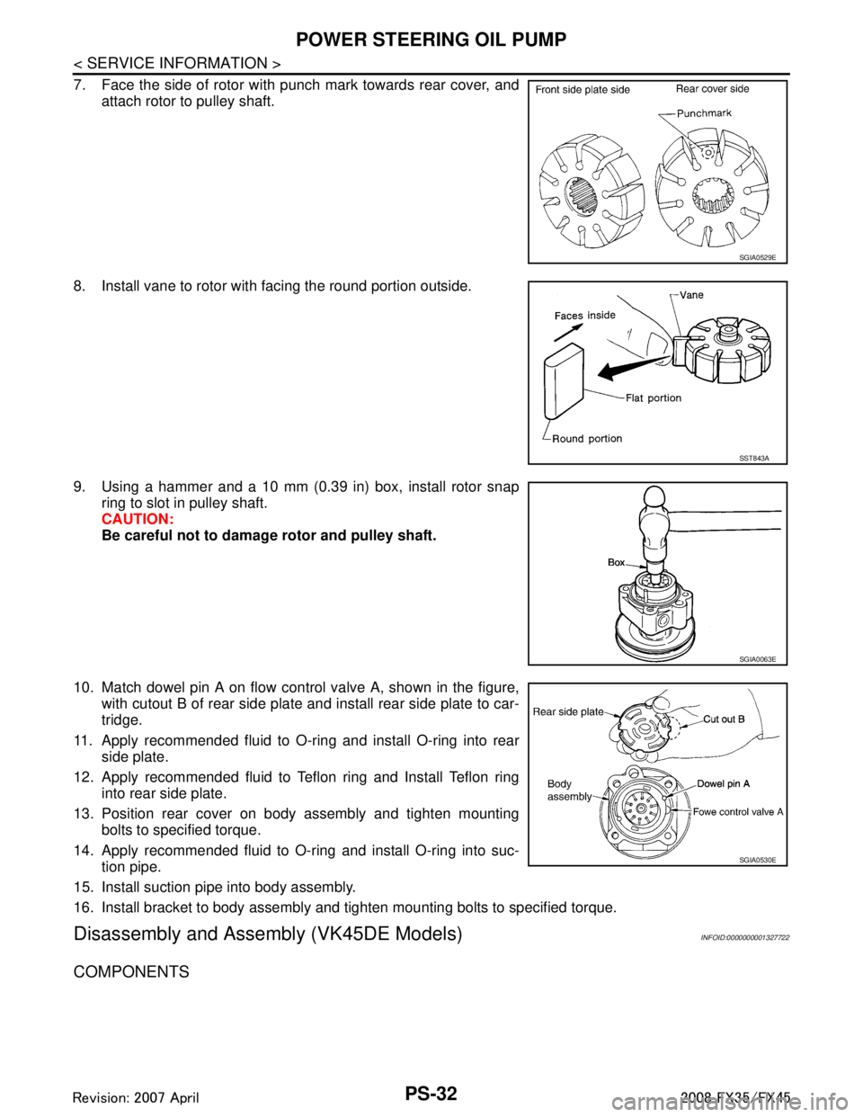
7. Face the side of rotor with punch mark towards rear cover, andattach rotor to pulley shaft.
8. Install vane to rotor with facing the round portion outside.
9. Using a hammer and a 10 mm (0.39 in) box, install rotor snap ring to slot in pulley shaft.
CAUTION:
Be careful not to damage rotor and pulley shaft.
10. Match dowel pin A on flow control valve A, shown in the figure, with cutout B of rear side plate and install rear side plate to car-
tridge.
11. Apply recommended fluid to O-ring and install O-ring into rear side plate.
12. Apply recommended fluid to Teflon ring and Install Teflon ring into rear side plate.
13. Position rear cover on body assembly and tighten mounting bolts to specified torque.
14. Apply recommended fluid to O-ring and install O-ring into suc- tion pipe.
15. Install suction pipe into body assembly.
16. Install bracket to body assembly and tighten mounting bolts to specified torque.
Disassembly and Assemb ly (VK45DE Models)INFOID:0000000001327722
COMPONENTS
SGIA0529E
SST843A
SGIA0063E
SGIA0530E
3AA93ABC3ACD3AC03ACA3AC03AC63AC53A913A773A893A873A873A8E3A773A983AC73AC93AC03AC3
3A893A873A873A8F3A773A9D3AAF3A8A3A8C3A863A9D3AAF3A8B3A8C
Page 3510 of 3924
RAX-12
< SERVICE INFORMATION >
REAR DRIVE SHAFT
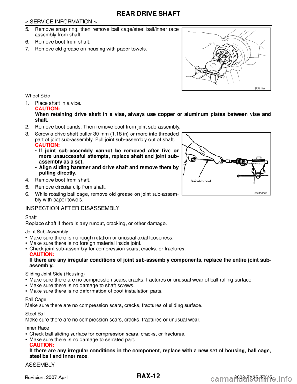
5. Remove snap ring, then remove ball cage/steel ball/inner raceassembly from shaft.
6. Remove boot from shaft.
7. Remove old grease on housing with paper towels.
Wheel Side
1. Place shaft in a vice. CAUTION:
When retaining drive shaft in a vise, always use copper or aluminum plates between vise and
shaft.
2. Remove boot bands. Then remove boot from joint sub-assembly.
3. Screw a drive shaft puller 30 mm (1.18 in) or more into threaded part of joint sub-assembly. Pull joint sub-assembly out of shaft.
CAUTION:
If joint sub-assembly cannot be removed after five ormore unsuccessful attempts, replace shaft and joint sub-
assembly as a set.
Align sliding hammer and drive shaft and remove them by pulling directly.
4. Remove boot from shaft.
5. Remove circular clip from shaft.
6. While rotating ball cage, remove old grease on joint sub-assem- bly with paper towels.
INSPECTION AFTER DISASSEMBLY
Shaft
Replace shaft if there is any runout, cracking, or other damage.
Joint Sub-Assembly
Make sure there is no rough rotation or unusual axial looseness.
Make sure there is no foreign material inside joint.
Check joint sub-assembly for compression scars, cracks, or fractures.
CAUTION:
If there are any irregular conditions of joint sub-assembly components, replace the entire joint sub-
assembly.
Sliding Joint Side (Housing)
Make sure there are no compression scars, cracks, fractures or unusual wear of ball rolling surface.
Make sure there is no damage to shaft screws.
Make sure there is no deformation of boot installation parts.
Ball Cage
Make sure there are no compression scars, cracks, fractures of sliding surface.
Steel Ball
Make sure there are no compression scars, cracks, fractures or unusual wear.
Inner Race
Check ball sliding surface for comp ression scars, cracks, or fractures.
Make sure there is no damage to serrated part.
CAUTION:
If there are any irregular conditions in the comp onent, replace with a new set of housing, ball cage,
steel ball and inner race.
ASSEMBLY
SFA514A
SDIA0606E
3AA93ABC3ACD3AC03ACA3AC03AC63AC53A913A773A893A873A873A8E3A773A983AC73AC93AC03AC3
3A893A873A873A8F3A773A9D3AAF3A8A3A8C3A863A9D3AAF3A8B3A8C
Page 3730 of 3924
FRONT SEATSE-91
< SERVICE INFORMATION >
C
DE
F
G H
J
K L
M A
B
SE
N
O P
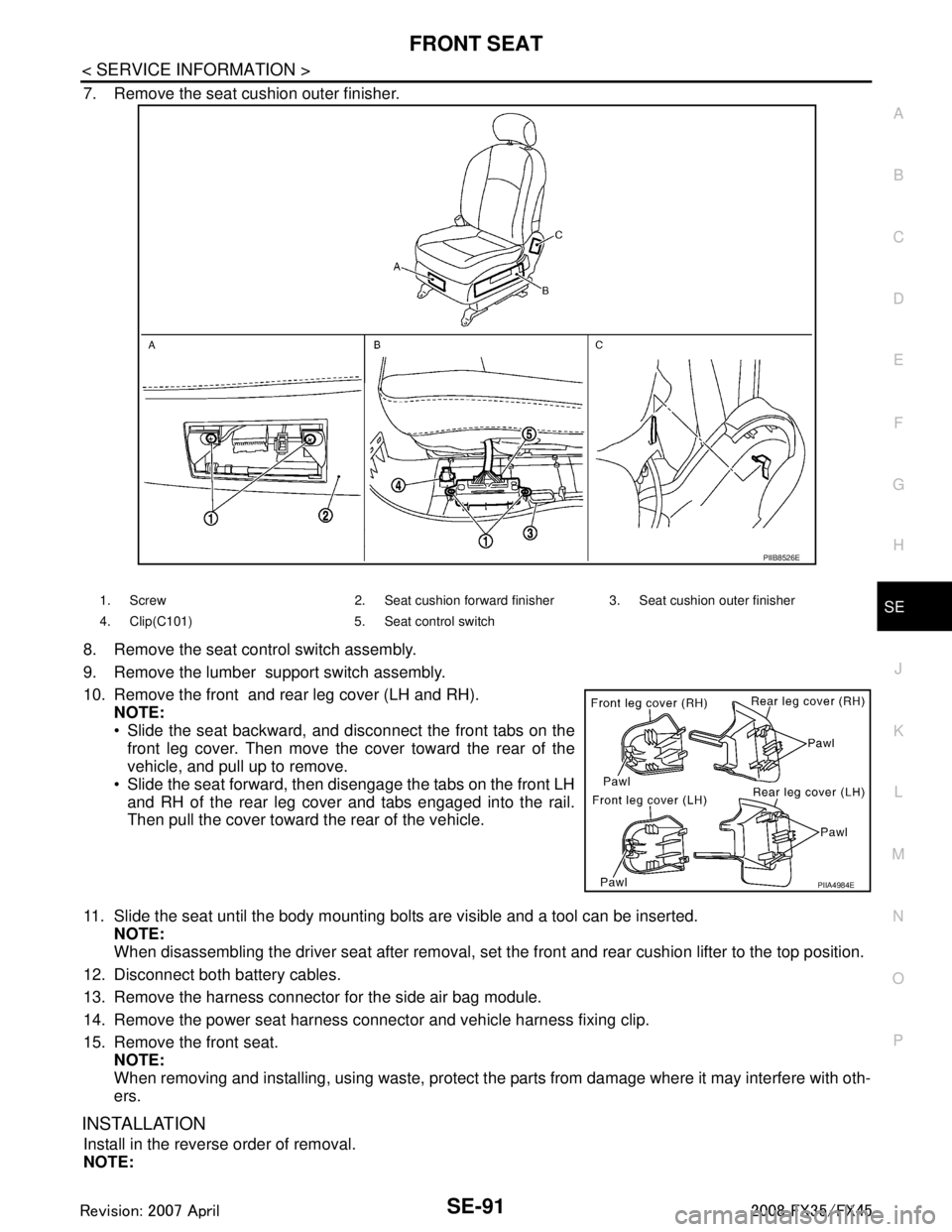
7. Remove the seat cushion outer finisher.
8. Remove the seat control switch assembly.
9. Remove the lumber support switch assembly.
10. Remove the front and rear leg cover (LH and RH). NOTE:
Slide the seat backward, and disconnect the front tabs on the
front leg cover. Then move the cover toward the rear of the
vehicle, and pull up to remove.
Slide the seat forward, then disengage the tabs on the front LH and RH of the rear leg cover and tabs engaged into the rail.
Then pull the cover toward the rear of the vehicle.
11. Slide the seat until the body mounting bolts are visible and a tool can be inserted. NOTE:
When disassembling the driver seat after removal, set the front and rear cushion lifter to the top position.
12. Disconnect both battery cables.
13. Remove the harness connector for the side air bag module.
14. Remove the power seat harness connector and vehicle harness fixing clip.
15. Remove the front seat. NOTE:
When removing and installing, using waste, protect t he parts from damage where it may interfere with oth-
ers.
INSTALLATION
Install in the reverse order of removal.
NOTE:
PIIB8526E
1. Screw 2. Seat cushion forward finisher 3. Seat cushion outer finisher
4. Clip(C101) 5. Seat control switch
PIIA4984E
3AA93ABC3ACD3AC03ACA3AC03AC63AC53A913A773A893A873A873A8E3A773A983AC73AC93AC03AC3
3A893A873A873A8F3A773A9D3AAF3A8A3A8C3A863A9D3AAF3A8B3A8C
Page 3744 of 3924
PRECAUTIONSSRS-7
< SERVICE INFORMATION >
C
DE
F
G
I
J
K L
M A
B
SRS
N
O P
PRECAUTIONS
Precaution for Supplemental Restraint System (SRS) "AIR BAG" and "SEAT BELT
PRE-TENSIONER"
INFOID:0000000001612877
The Supplemental Restraint System such as “A IR BAG” and “SEAT BELT PRE-TENSIONER”, used along
with a front seat belt, helps to reduce the risk or severi ty of injury to the driver and front passenger for certain
types of collision. This system includes seat belt switch inputs and dual stage front air bag modules. The SRS
system uses the seat belt switches to determine the front air bag deployment, and may only deploy one front
air bag, depending on the severity of a collision and whether the front occupants are belted or unbelted.
Information necessary to service the system safely is included in the “SUPPLEMENTAL RESTRAINT SYS-
TEM” and “SEAT BELTS” of this Service Manual.
WARNING:
• To avoid rendering the SRS inoper ative, which could increase the risk of personal injury or death in
the event of a collision which would result in air bag inflation, all maintenance must be performed by
an authorized NISSAN/INFINITI dealer.
Improper maintenance, including in correct removal and installation of the SRS, can lead to personal
injury caused by unintentional act ivation of the system. For removal of Spiral Cable and Air Bag
Module, see the “SUPPLEMEN TAL RESTRAINT SYSTEM”.
Do not use electrical test equipm ent on any circuit related to the SRS unless instructed to in this
Service Manual. SRS wiring harnesses can be identi fied by yellow and/or orange harnesses or har-
ness connectors.
Precaution for SRS "AIR BAG" and "SEAT BELT PRE-TENSIONER" Service
INFOID:0000000001327741
Do not use electrical test equipment to check SRS ci rcuits unless instructed to in this Service Manual.
Before servicing the SRS, turn ignition switch OFF, disconnect both battery cables and wait at least 3 min-
utes.
For approximately 3 minutes after the cables are remov ed, it is still possible for the air bag and seat belt pre-
tensioner to deploy. Therefore, do not work on any SR S connectors or wires until at least 3 minutes have
passed.
Diagnosis sensor unit must always be installed with their arrow marks “ ⇐” pointing towards the front of the
vehicle for proper operation. Also check diagnosis sensor unit for cracks, deformities or rust before installa-
tion and replace as required.
The spiral cable must be aligned with the neutral position since its rotations are limited. Do not turn steering
wheel and column after removal of steering gear.
Handle air bag module carefully. Always place driver and front passenger air bag modules with the pad side facing upward and seat mounted front side air bag module standing with the stud bolt side facing down.
Conduct self-diagnosis to check entire SRS for proper function after replacing any components.
After air bag inflates, the front instrument panel assembly should be replaced if damaged.
Always replace instrument panel pad following front passenger air bag deployment.
Disposal, recycling, and transportation of air bag m odules and seat belt pre-tensioners should be performed
in compliance with applicable federal, state and local laws and regulations.
Occupant Classification System PrecautionINFOID:0000000001327742
Replace occupant classification system control uni t and passenger front seat cushion as an assembly.
Refer to Refer to Service Manual .
3AA93ABC3ACD3AC03ACA3AC03AC63AC53A913A773A893A873A873A8E3A773A983AC73AC93AC03AC3
3A893A873A873A8F3A773A9D3AAF3A8A3A8C3A863A9D3AAF3A8B3A8C
Page 3791 of 3924
PRECAUTIONSTF-5
< SERVICE INFORMATION >
CEF
G H
I
J
K L
M A
B
TF
N
O P
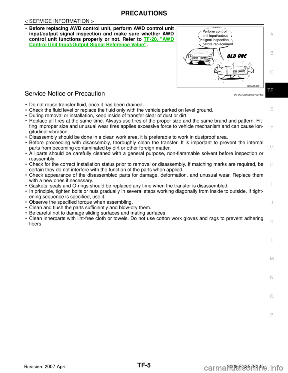
Before replacing AWD control unit, perform AWD control unit
input/output signal inspection and make sure whether AWD
control unit functions properly or not. Refer to TF-20, "
AW D
Control Unit Input/Output Signal Reference Value".
Service Notice or PrecautionINFOID:0000000001327425
Do not reuse transfer fluid, once it has been drained.
Check the fluid level or replace the fluid only with the vehicle parked on level ground.
During removal or installation, keep inside of transfer clear of dust or dirt.
Replace all tires at the same time. Always use tires of the proper size and the same brand and pattern. Fit-
ting improper size and unusual wear tires applies excessive force to vehicle mechanism and can cause lon-
gitudinal vibration.
Disassembly should be done in a clean work area, it is preferable to work in dustproof area.
Before proceeding with disassembly, thoroughly clean the tr ansfer. It is important to prevent the internal
parts from becoming contaminated by dirt or other foreign matter.
All parts should be carefully cleaned with a general purpose, non-flammable solvent before inspection or
reassembly.
Check for the correct installation status prior to remo val or disassembly. If matching marks are required, be
certain they do not interfere with t he function of the parts when applied.
Check appearance of the disassembled parts for dam age, deformation, and unusual wear. Replace them
with a new ones if necessary.
Gaskets, seals and O-rings should be replaced any time when the transfer is disassembled.
In principle, tighten bolts or nuts gradually in several steps working diagonally from inside to outside. If tight-
ening sequence is specified, use it.
Observe the specified torque when assembling.
Clean and flush the parts sufficiently and blow-dry them.
Be careful not to damage sliding surfaces and mating surfaces.
Clean innerparts with lint-free cloth or towels. Do not use cotton work gloves and rags to prevent adhering
fibers.
SDIA1848E
3AA93ABC3ACD3AC03ACA3AC03AC63AC53A913A773A893A873A873A8E3A773A983AC73AC93AC03AC3
3A893A873A873A8F3A773A9D3AAF3A8A3A8C3A863A9D3AAF3A8B3A8C
Page 3903 of 3924
WW-28
< SERVICE INFORMATION >
FRONT WIPER AND WASHER SYSTEM
Inspection of Front Wiper and Washer Switch Circuit
INFOID:0000000001328572
Refer to LT-104, "Combination Switch Inspection".
Removal and Installation of Fr ont Wiper and Washer SwitchINFOID:0000000001328573
REMOVAL
1. Remove steering column upper cover. Refer to IP-10, "Compo-
nent Parts Location".
2. Disconnect wiper and washer switch connector.
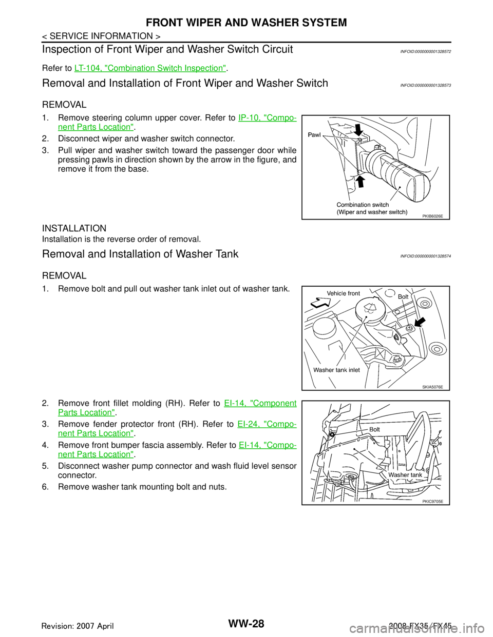
3. Pull wiper and washer switch toward the passenger door while pressing pawls in direction shown by the arrow in the figure, and
remove it from the base.
INSTALLATION
Installation is the reverse order of removal.
Removal and Installation of Washer TankINFOID:0000000001328574
REMOVAL
1. Remove bolt and pull out washer tank inlet out of washer tank.
2. Remove front fillet molding (RH). Refer to EI-14, "
Component
Parts Location".
3. Remove fender protector front (RH). Refer to EI-24, "
Compo-
nent Parts Location".
4. Remove front bumper fascia assembly. Refer to EI-14, "
Compo-
nent Parts Location".
5. Disconnect washer pump connector and wash fluid level sensor connector.
6. Remove washer tank mounting bolt and nuts.
PKIB6026E
SKIA5076E
PKIC9705E
3AA93ABC3ACD3AC03ACA3AC03AC63AC53A913A773A893A873A873A8E3A773A983AC73AC93AC03AC3
3A893A873A873A8F3A773A9D3AAF3A8A3A8C3A863A9D3AAF3A8B3A8C