2008 INFINITI FX35 tow
[x] Cancel search: towPage 3132 of 3924
LT-30
< SERVICE INFORMATION >
HEADLAMP - XENON TYPE -
After installing bulb, be sure to install plastic cap and bulb socket securely to insure watertight-
ness.
Removal and InstallationINFOID:0000000001328289
REMOVAL
1. Disconnect the battery cable from the negative terminal or remove power fuse.
2. Remove front bumper fascia assembly. Refer to EI-14, "
Compo-
nent Parts Location".
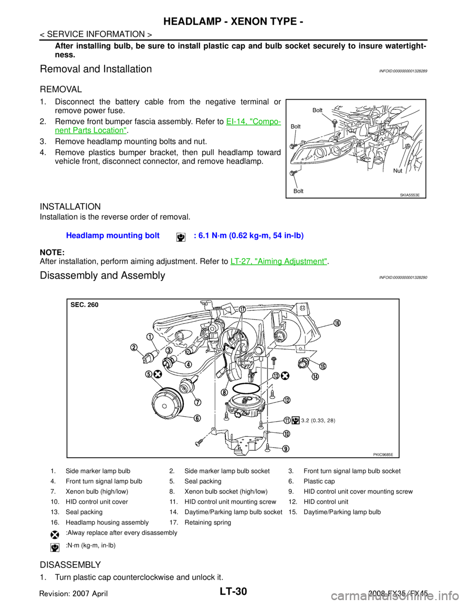
3. Remove headlamp mounting bolts and nut.
4. Remove plastics bumper bracket, then pull headlamp toward vehicle front, disconnect connector, and remove headlamp.
INSTALLATION
Installation is the reverse order of removal.
NOTE:
After installation, perform aiming adjustment. Refer to LT-27, "
Aiming Adjustment".
Disassembly and AssemblyINFOID:0000000001328290
DISASSEMBLY
1. Turn plastic cap counterclockwise and unlock it.
SKIA5553E
Headlamp mounting bolt : 6.1 N·m (0.62 kg-m, 54 in-lb)
1. Side marker lamp bulb 2. Side marker lamp bulb socket 3. Front turn signal lamp bulb socket
4. Front turn signal lamp bulb 5. Seal packing 6. Plastic cap
7. Xenon bulb (high/low) 8. Xenon bulb socket (high/low) 9. HID control unit cover mounting screw
10. HID control unit cover 11. HID control unit mounting screw 12. HID control unit
13. Seal packing 14. Daytime/Parking lamp bulb socket 15. Daytime/Parking lamp bulb
16. Headlamp housing assembly 17. Retaining spring
:Alway replace after every disassembly
:N·m (kg-m, in-lb)
PKIC9685E
3AA93ABC3ACD3AC03ACA3AC03AC63AC53A913A773A893A873A873A8E3A773A983AC73AC93AC03AC3
3A893A873A873A8F3A773A9D3AAF3A8A3A8C3A863A9D3AAF3A8B3A8C
Page 3198 of 3924
LT-96
< SERVICE INFORMATION >
LIGHTING AND TURN SIGNAL SWITCH
LIGHTING AND TURN SIGNAL SWITCH
Removal and InstallationINFOID:0000000001328362
REMOVAL
1. Remove steering column cover. Refer to IP-10.
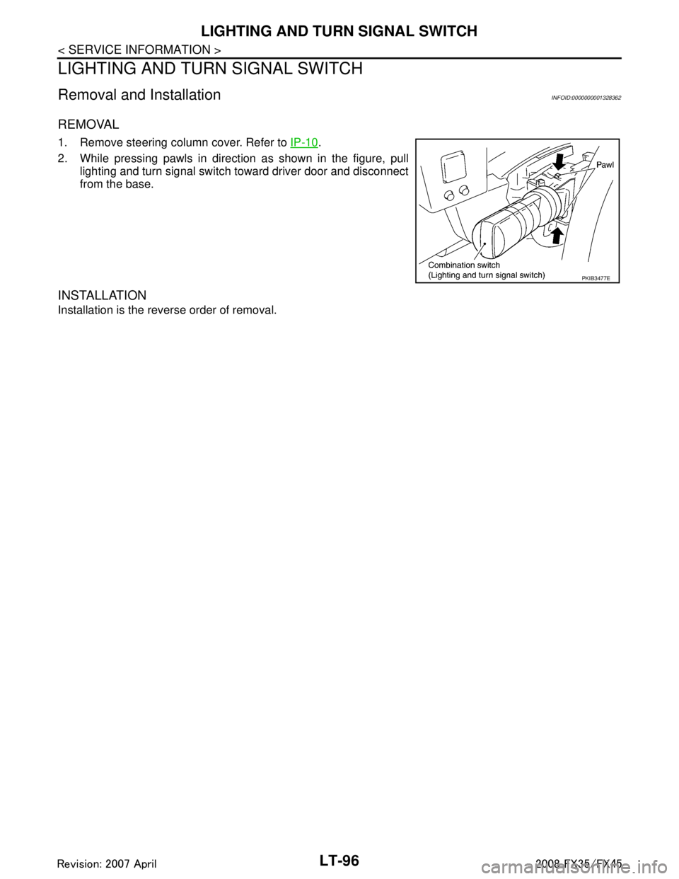
2. While pressing pawls in direction as shown in the figure, pull lighting and turn signal switch toward driver door and disconnect
from the base.
INSTALLATION
Installation is the reverse order of removal.
PKIB3477E
3AA93ABC3ACD3AC03ACA3AC03AC63AC53A913A773A893A873A873A8E3A773A983AC73AC93AC03AC3
3A893A873A873A8F3A773A9D3AAF3A8A3A8C3A863A9D3AAF3A8B3A8C
Page 3239 of 3924
REAR COMBINATION LAMPLT-137
< SERVICE INFORMATION >
C
DE
F
G H
I
J
L
M A
B
LT
N
O P
REAR COMBINATION LAMP
Bulb ReplacementINFOID:0000000001328404
REAR FENDER SIDE (REAR SIDE MARKER LAMP BULB)
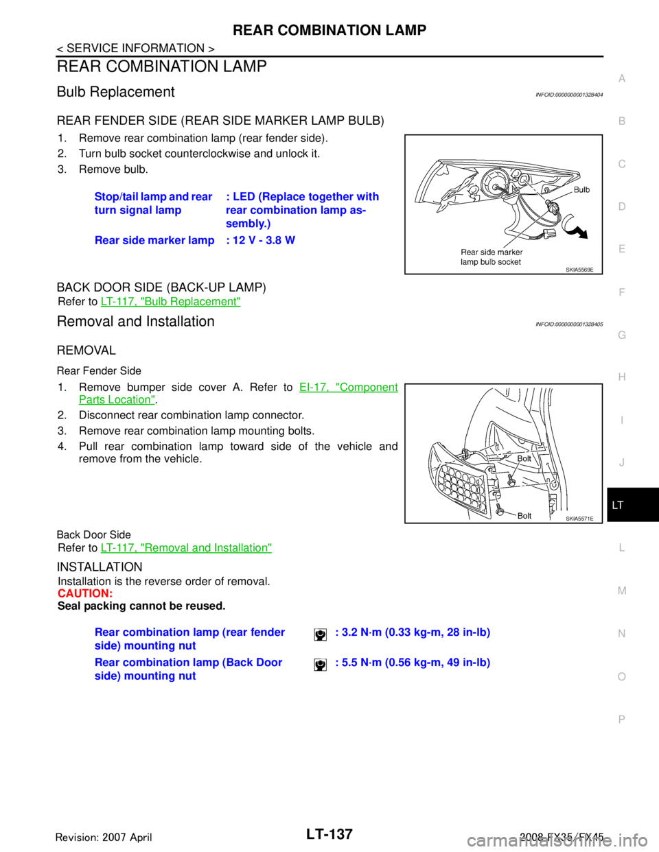
1. Remove rear combination lamp (rear fender side).
2. Turn bulb socket counterclockwise and unlock it.
3. Remove bulb.
BACK DOOR SIDE (BACK-UP LAMP)
Refer to LT-117, "Bulb Replacement"
Removal and InstallationINFOID:0000000001328405
REMOVAL
Rear Fender Side
1. Remove bumper side cover A. Refer to EI-17, "Component
Parts Location".
2. Disconnect rear combination lamp connector.
3. Remove rear combination lamp mounting bolts.
4. Pull rear combination lamp toward side of the vehicle and remove from the vehicle.
Back Door Side
Refer to LT-117, "Removal and Installation"
INSTALLATION
Installation is the reverse order of removal.
CAUTION:
Seal packing cannot be reused.Stop/tail lamp and rear
turn signal lamp
: LED (Replace together with
rear combination lamp as-
sembly.)
Rear side marker lamp : 12 V - 3.8 W
SKIA5569E
SKIA5571E
Rear combination lamp (rear fender
side) mounting nut : 3.2 N·m (0.33 kg-m, 28 in-lb)
Rear combination lamp (Back Door
side) mounting nut : 5.5 N·m (0.56 kg-m, 49 in-lb)
3AA93ABC3ACD3AC03ACA3AC03AC63AC53A913A773A893A873A873A8E3A773A983AC73AC93AC03AC3
3A893A873A873A8F3A773A9D3AAF3A8A3A8C3A863A9D3AAF3A8B3A8C
Page 3322 of 3924
PERIODIC MAINTENANCEMA-5
< SERVICE INFORMATION >
C
DE
F
G H
I
J
K
M A
B
MA
N
O P
PERIODIC MAINTENANCE
Introduction of Periodic MaintenanceINFOID:0000000001328894
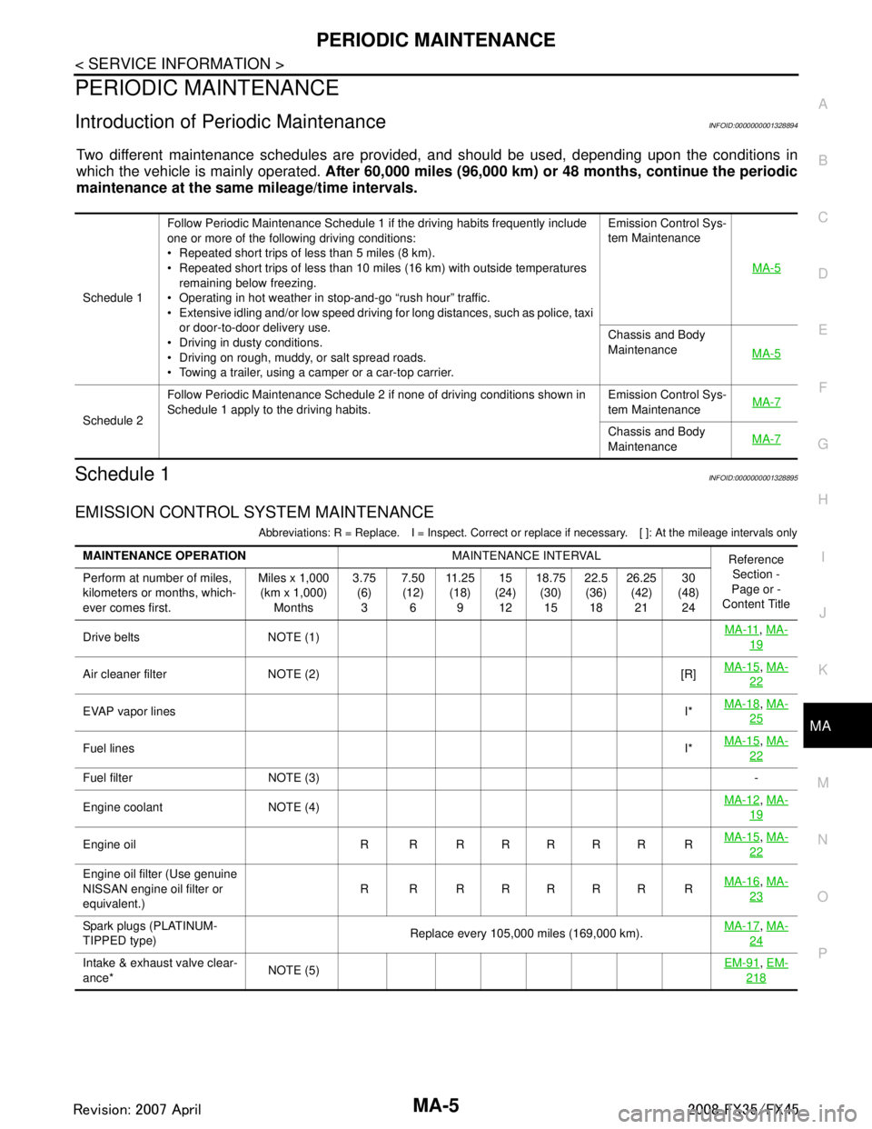
Two different maintenance schedules are provi ded, and should be used, depending upon the conditions in
which the vehicle is mainly operated. After 60,000 miles (96,000 km) or 48 months, continue the periodic
maintenance at the same mileage/time intervals.
Schedule 1INFOID:0000000001328895
EMISSION CONTROL SYSTEM MAINTENANCE
Abbreviations: R = Replace. I = Inspect. Correct or r eplace if necessary. [ ]: At the mileage intervals only
Schedule 1Follow Periodic Maintenance Schedule 1 if the driving habits frequently include
one or more of the following driving conditions:
Repeated short trips of less than 5 miles (8 km).
Repeated short trips of less than 10 miles (16 km) with outside temperatures
remaining below freezing.
Operating in hot weather in stop-and-go “rush hour” traffic.
Extensive idling and/or low speed driving for long distances, such as police, taxi or door-to-door delivery use.
Driving in dusty conditions.
Driving on rough, muddy, or salt spread roads.
Towing a trailer, using a camper or a car-top carrier. Emission Control Sys-
tem Maintenance
MA-5
Chassis and Body
MaintenanceMA-5
Schedule 2Follow Periodic Maintenance Schedule 2 if none of driving conditions shown in
Schedule 1 apply to the driving habits.
Emission Control Sys-
tem Maintenance
MA-7Chassis and Body
Maintenance
MA-7
MAINTENANCE OPERATION
MAINTENANCE INTERVAL
Reference
Section -
Page or -
Content Title
Perform at number of miles,
kilometers or months, which-
ever comes first. Miles x 1,000
(km x 1,000) Months 3.75
(6)3 7.50
(12) 6 11 . 2 5
(18) 9 15
(24) 12 18.75
(30)15 22.5
(36) 18 26.25
(42)21 30
(48) 24
Drive belts NOTE (1) MA-11
,
MA-
19
Air cleaner filter NOTE (2) [R] MA-15,
MA-
22
EVAP vapor lines I*MA-18,
MA-
25
Fuel lines I*MA-15,
MA-
22
Fuel filter NOTE (3) -
Engine coolant NOTE (4) MA-12
,
MA-
19
Engine oil R R R R R R R R MA-15,
MA-
22
Engine oil filter (Use genuine
NISSAN engine oil filter or
equivalent.) R R RRRRR R
MA-16,
MA-
23
Spark plugs (PLATINUM-
TIPPED type) Replace every 105,000 miles (169,000 km).
MA-17,
MA-
24
Intake & exhaust valve clear-
ance* NOTE (5) EM-91,
EM-
218
3AA93ABC3ACD3AC03ACA3AC03AC63AC53A913A773A893A873A873A8E3A773A983AC73AC93AC03AC3
3A893A873A873A8F3A773A9D3AAF3A8A3A8C3A863A9D3AAF3A8B3A8C
Page 3324 of 3924
PERIODIC MAINTENANCEMA-7
< SERVICE INFORMATION >
C
DE
F
G H
I
J
K
M A
B
MA
N
O P
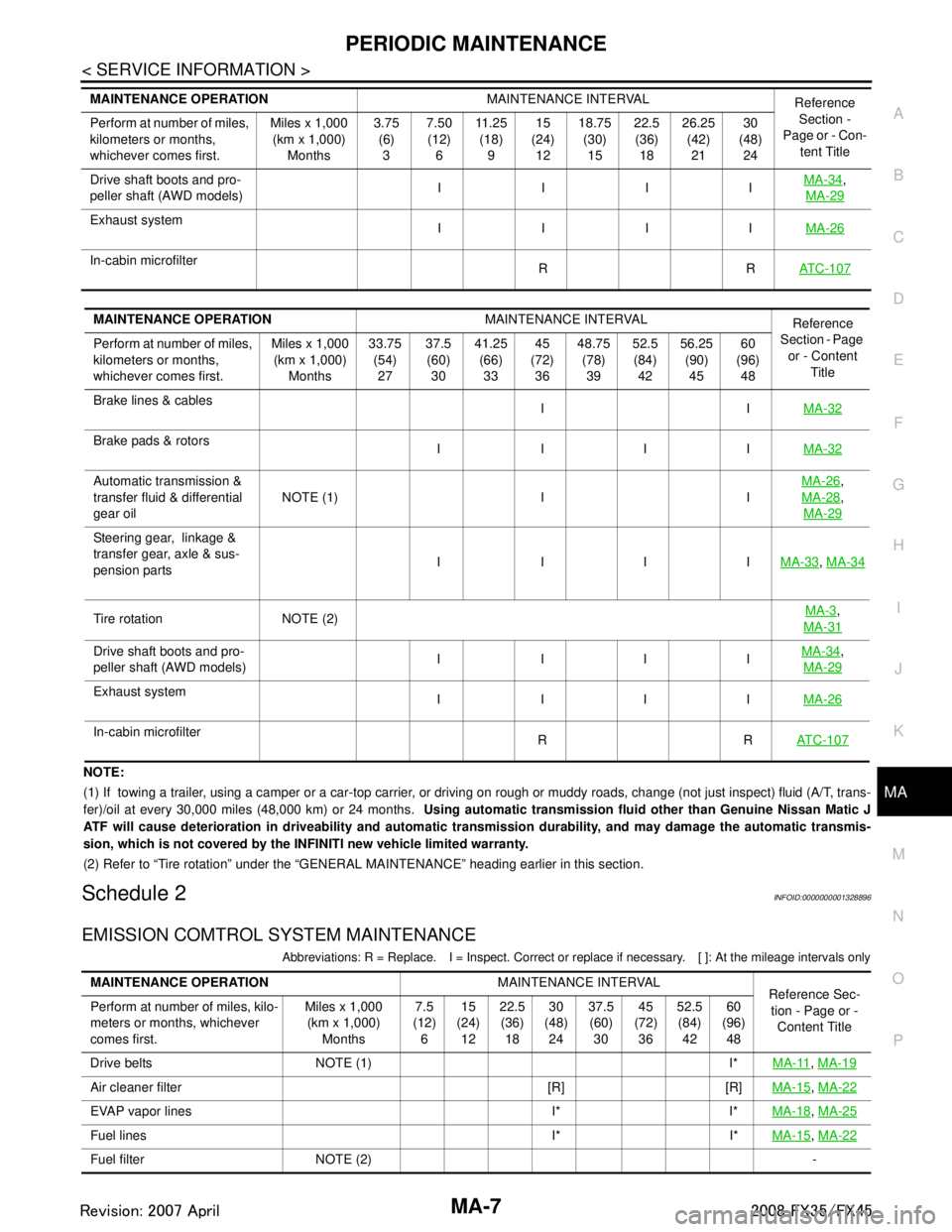
NOTE:
(1) If towing a trailer, using a camper or a car-top carrier, or driving on rough or muddy roads, change (not just inspect) fl uid (A/T, trans-
fer)/oil at every 30,000 miles (48,000 km) or 24 months. Using automatic transmission fluid other than Genuine Nissan Matic J
ATF will cause deterioration in driveability and automatic transmission durability, and may damage the automatic transmis-
sion, which is not covered by the INFINITI new vehicle limited warranty.
(2) Refer to “Tire rotation” under the “GENERAL MAINTENANCE” heading earlier in this section.
Schedule 2INFOID:0000000001328896
EMISSION COMTROL SYSTEM MAINTENANCE
Abbreviations: R = Replace. I = Inspect. Correct or r eplace if necessary. [ ]: At the mileage intervals only
Drive shaft boots and pro-
peller shaft (AWD models) IIII
MA-34,
MA-29
Exhaust system IIII MA-26
In-cabin microfilter
RRAT C - 1 0 7
MAINTENANCE OPERATION MAINTENANCE INTERVAL
Reference
Section -
Page or - Con- tent Title
Perform at number of miles,
kilometers or months,
whichever comes first. Miles x 1,000
(km x 1,000)
Months 3.75
(6)
3 7.50
(12)
6 11 . 2 5
(18)
9 15
(24)
12 18.75
(30)
15 22.5
(36)
18 26.25
(42)
21 30
(48)
24
MAINTENANCE OPERATION MAINTENANCE INTERVAL
Reference
Section - Page
or - Content Title
Perform at number of miles,
kilometers or months,
whichever comes first. Miles x 1,000
(km x 1,000) Months 33.75
(54)27 37.5
(60) 30 41.25
(66)33 45
(72) 36 48.75
(78)39 52.5
(84) 42 56.25
(90)45 60
(96) 48
Brake lines & cables IIMA-32
Brake pads & rotors
IIII MA-32
Automatic transmission &
transfer fluid & differential
gear oilNOTE (1) I I
MA-26,
MA-28
,
MA-29
Steering gear, linkage &
transfer gear, axle & sus-
pension parts IIII
MA-33
, MA-34
Tire rotation NOTE (2) MA-3,
MA-31
Drive shaft boots and pro-
peller shaft (AWD models) IIII MA-34,
MA-29
Exhaust system IIII MA-26
In-cabin microfilter
RRAT C - 1 0 7
MAINTENANCE OPERATION MAINTENANCE INTERVAL
Reference Sec-
tion - Page or - Content Title
Perform at number of miles, kilo-
meters or months, whichever
comes first. Miles x 1,000
(km x 1,000) Months 7.5
(12) 6 15
(24) 12 22.5
(36) 18 30
(48) 24 37.5
(60) 30 45
(72) 36 52.5
(84) 42 60
(96) 48
Drive belts NOTE (1) I* MA-11
, MA-19
Air cleaner filter [R] [R] MA-15, MA-22
EVAP vapor lines I* I* MA-18, MA-25
Fuel lines I* I* MA-15, MA-22
Fuel filter NOTE (2) -
3AA93ABC3ACD3AC03ACA3AC03AC63AC53A913A773A893A873A873A8E3A773A983AC73AC93AC03AC3
3A893A873A873A8F3A773A9D3AAF3A8A3A8C3A863A9D3AAF3A8B3A8C
Page 3389 of 3924
IPDM E/R (INTELLIGENT POWER DISTRIBUTION MODULE ENGINE ROOM)
PG-25
< SERVICE INFORMATION >
C
D E
F
G H
I
J
L
M A
B
PG
N
O P
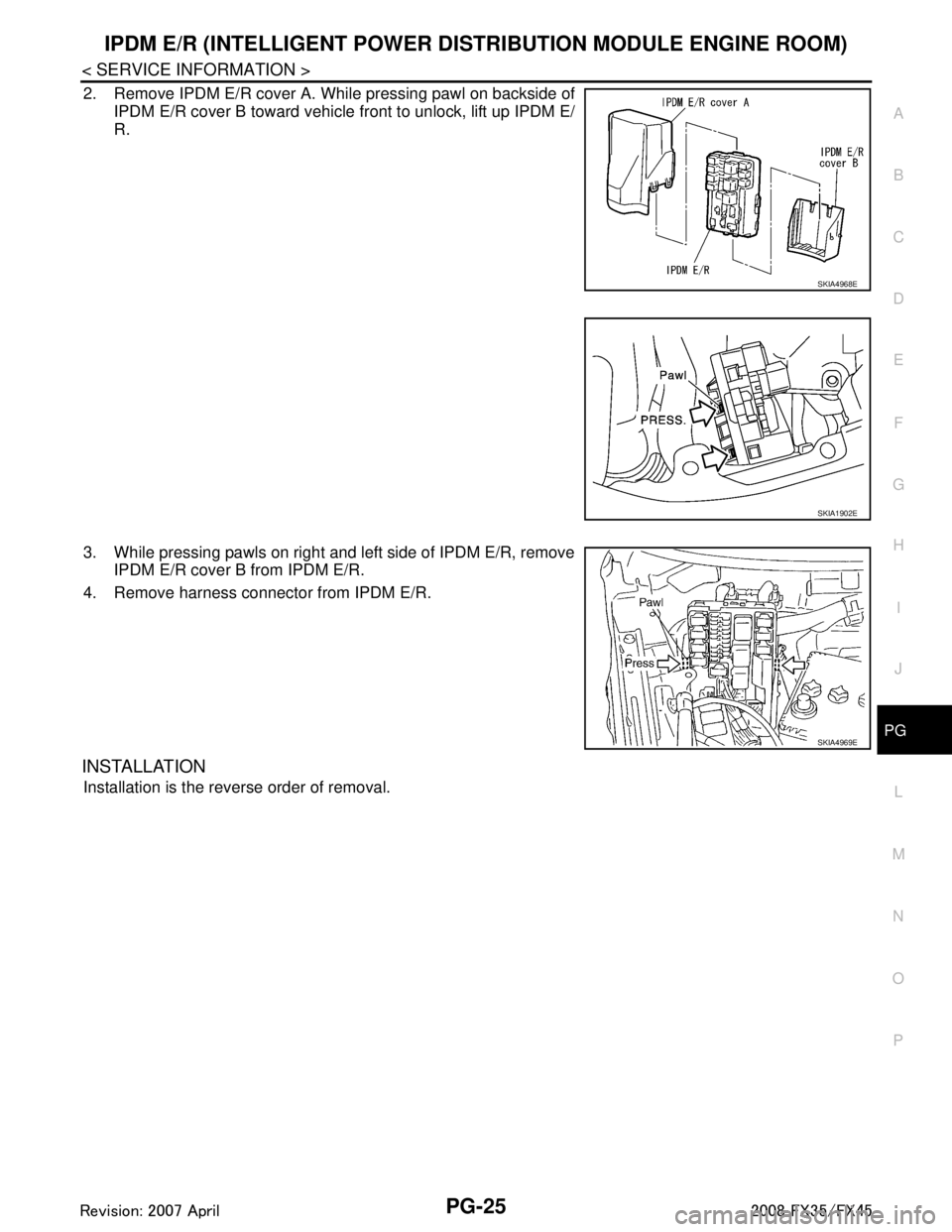
2. Remove IPDM E/R cover A. While pressing pawl on backside of IPDM E/R cover B toward vehicle front to unlock, lift up IPDM E/
R.
3. While pressing pawls on right and left side of IPDM E/R, remove IPDM E/R cover B from IPDM E/R.
4. Remove harness connector from IPDM E/R.
INSTALLATION
Installation is the reverse order of removal.
SKIA4968E
SKIA1902E
SKIA4969E
3AA93ABC3ACD3AC03ACA3AC03AC63AC53A913A773A893A873A873A8E3A773A983AC73AC93AC03AC3
3A893A873A873A8F3A773A9D3AAF3A8A3A8C3A863A9D3AAF3A8B3A8C
Page 3452 of 3924
PR-10
< SERVICE INFORMATION >
REAR PROPELLER SHAFT
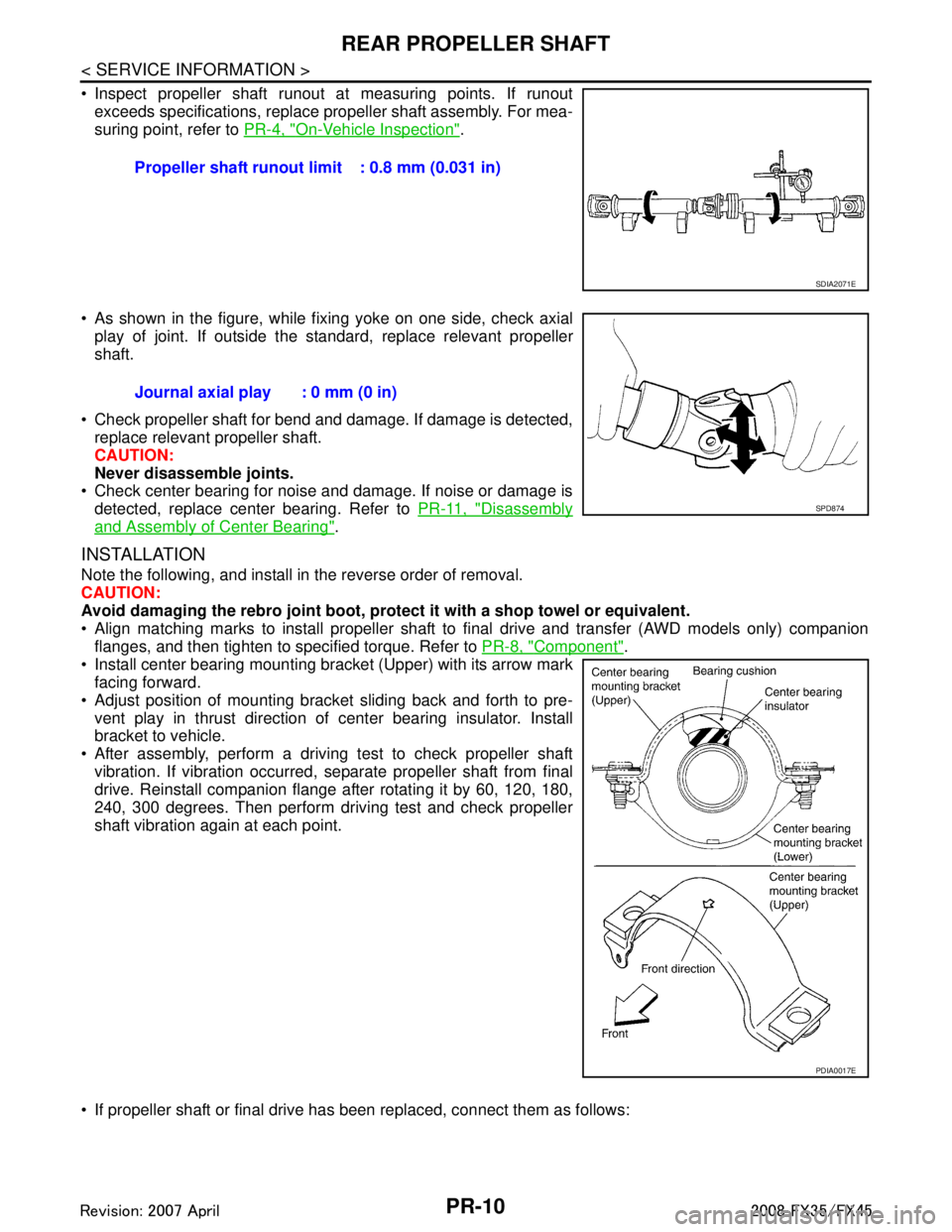
Inspect propeller shaft runout at measuring points. If runoutexceeds specifications, replace propeller shaft assembly. For mea-
suring point, refer to PR-4, "
On-Vehicle Inspection".
As shown in the figure, while fixing yoke on one side, check axial play of joint. If outside the standard, replace relevant propeller
shaft.
Check propeller shaft for bend and damage. If damage is detected, replace relevant propeller shaft.
CAUTION:
Never disassemble joints.
Check center bearing for noise and damage. If noise or damage is
detected, replace center bearing. Refer to PR-11, "
Disassembly
and Assembly of Center Bearing".
INSTALLATION
Note the following, and install in the reverse order of removal.
CAUTION:
Avoid damaging the rebro joint boot, protect it with a shop towel or equivalent.
Align matching marks to install propeller shaft to final drive and transfer (AWD models only) companion
flanges, and then tighten to specified torque. Refer to PR-8, "
Component".
Install center bearing mounting bracket (Upper) with its arrow mark
facing forward.
Adjust position of mounting bracket sliding back and forth to pre- vent play in thrust direction of center bearing insulator. Install
bracket to vehicle.
After assembly, perform a driving test to check propeller shaft vibration. If vibration occurred, separate propeller shaft from final
drive. Reinstall companion flange after rotating it by 60, 120, 180,
240, 300 degrees. Then perform driving test and check propeller
shaft vibration again at each point.
If propeller shaft or final drive has been replaced, connect them as follows: Propeller shaft runout limit : 0.8 mm (0.031 in)
SDIA2071E
Journal axial play : 0 mm (0 in)
SPD874
PDIA0017E
3AA93ABC3ACD3AC03ACA3AC03AC63AC53A913A773A893A873A873A8E3A773A983AC73AC93AC03AC3
3A893A873A873A8F3A773A9D3AAF3A8A3A8C3A863A9D3AAF3A8B3A8C
Page 3458 of 3924
PRECAUTIONSPS-3
< SERVICE INFORMATION >
C
DE
F
H I
J
K L
M A
B
PS
N
O P
- Before disassembly, thoroughly clean the outside of the unit.
- Disassembly should be done in a clean work area. It is im portant to prevent the internal parts from becoming
contaminated by dirt or other foreign matter.
- For easier and proper assembly, place disassembled parts in order on a parts rack.
- Use nylon cloth or paper towels to clean the parts; common shop rags can leave lint that might interfere with
their operation.
- Do not reuse non-reusable parts.
- Before assembling, apply the specified grease to the directed parts.
3AA93ABC3ACD3AC03ACA3AC03AC63AC53A913A773A893A873A873A8E3A773A983AC73AC93AC03AC3
3A893A873A873A8F3A773A9D3AAF3A8A3A8C3A863A9D3AAF3A8B3A8C