2008 INFINITI FX35 oil type
[x] Cancel search: oil typePage 3106 of 3924
LT-4
< SERVICE INFORMATION >
PRECAUTIONS
SERVICE INFORMATION
PRECAUTIONS
Precaution for Supplemental Restraint System (SRS) "AIR BAG" and "SEAT BELT
PRE-TENSIONER"
INFOID:0000000001612924
The Supplemental Restraint System such as “A IR BAG” and “SEAT BELT PRE-TENSIONER”, used along
with a front seat belt, helps to reduce the risk or severi ty of injury to the driver and front passenger for certain
types of collision. This system includes seat belt switch inputs and dual stage front air bag modules. The SRS
system uses the seat belt switches to determine the front air bag deployment, and may only deploy one front
air bag, depending on the severity of a collision and w hether the front occupants are belted or unbelted.
Information necessary to service the system safely is included in the “SUPPLEMENTAL RESTRAINT SYS-
TEM” and “SEAT BELTS” of this Service Manual.
WARNING:
• To avoid rendering the SRS inopera tive, which could increase the risk of personal injury or death in
the event of a collision which would result in air bag inflation, all maintenance must be performed by
an authorized NISS AN/INFINITI dealer.
Improper maintenance, including in correct removal and installation of the SRS, can lead to personal
injury caused by unintent ional activation of the system. For re moval of Spiral Cable and Air Bag
Module, see the “SUPPLEMEN TAL RESTRAINT SYSTEM”.
Do not use electrical test equipmen t on any circuit related to the SRS unless instructed to in this
Service Manual. SRS wiring harnesses can be identi fied by yellow and/or orange harnesses or har-
ness connectors.
General Precaution for Service OperationINFOID:0000000001328264
Never work with wet hands.
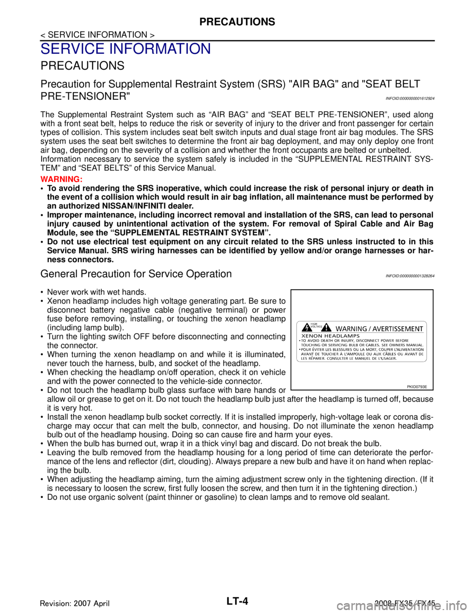
Xenon headlamp includes high voltage generating part. Be sure to disconnect battery negative cable (negative terminal) or power
fuse before removing, installing, or touching the xenon headlamp
(including lamp bulb).
Turn the lighting switch OFF before disconnecting and connecting the connector.
When turning the xenon headlamp on and while it is illuminated, never touch the harness, bulb, and socket of the headlamp.
When checking the headlamp on/off operation, check it on vehicle
and with the power connected to the vehicle-side connector.
Do not touch the headlamp bulb glass surface with bare hands or allow oil or grease to get on it. Do not touch the headl amp bulb just after the headlamp is turned off, because
it is very hot.
Install the xenon headlamp bulb socket co rrectly. If it is installed improperly, high-voltage leak or corona dis-
charge may occur that can melt the bulb, connecto r, and housing. Do not illuminate the xenon headlamp
bulb out of the headlamp housing. Doing so can cause fire and harm your eyes.
When the bulb has burned out, wrap it in a thick vinyl bag and discard. Do not break the bulb.
Leaving the bulb removed from the headlamp housing for a long period of time can deteriorate the perfor- mance of the lens and reflector (dirt, clouding). Al ways prepare a new bulb and have it on hand when replac-
ing the bulb.
When adjusting the headlamp aiming, turn the aiming adjus tment screw only in the tightening direction. (If it
is necessary to loosen the screw, first fully loosen the screw, and then turn it in the tightening direction.)
Do not use organic solvent (paint thinner or gasoline) to clean lamps and to remove old sealant.
PKID0793E
3AA93ABC3ACD3AC03ACA3AC03AC63AC53A913A773A893A873A873A8E3A773A983AC73AC93AC03AC3
3A893A873A873A8F3A773A9D3AAF3A8A3A8C3A863A9D3AAF3A8B3A8C
Page 3107 of 3924
HEADLAMP - XENON TYPE -LT-5
< SERVICE INFORMATION >
C
DE
F
G H
I
J
L
M A
B
LT
N
O P
HEADLAMP - XENON TYPE -
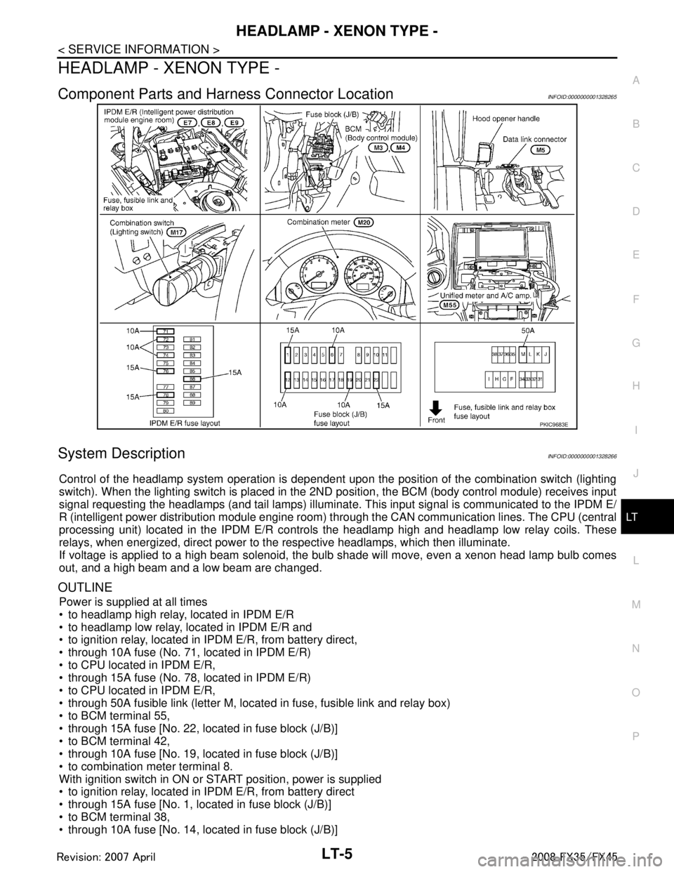
Component Parts and Har ness Connector LocationINFOID:0000000001328265
System DescriptionINFOID:0000000001328266
Control of the headlamp system operation is dependent upon t he position of the combination switch (lighting
switch). When the lighting switch is placed in the 2ND position, the BCM (body control module) receives input
signal requesting the headlamps (and tail lamps) illuminate. This input signal is communicated to the IPDM E/
R (intelligent power distribution module engine room) through the CAN communication lines. The CPU (central
processing unit) located in the IPDM E/R contro ls the headlamp high and headlamp low relay coils. These
relays, when energized, direct power to the respective headlamps, which then illuminate.
If voltage is applied to a high beam solenoid, the bulb shade will move, even a xenon head lamp bulb comes
out, and a high beam and a low beam are changed.
OUTLINE
Power is supplied at all times
to headlamp high relay, located in IPDM E/R
to headlamp low relay, located in IPDM E/R and
to ignition relay, located in IPDM E/R, from battery direct,
through 10A fuse (No. 71, located in IPDM E/R)
to CPU located in IPDM E/R,
through 15A fuse (No. 78, located in IPDM E/R)
to CPU located in IPDM E/R,
through 50A fusible link (letter M, located in fuse, fusible link and relay box)
to BCM terminal 55,
through 15A fuse [No. 22, located in fuse block (J/B)]
to BCM terminal 42,
through 10A fuse [No. 19, located in fuse block (J/B)]
to combination meter terminal 8.
With ignition switch in ON or START position, power is supplied
to ignition relay, located in IPDM E/R, from battery direct
through 15A fuse [No. 1, located in fuse block (J/B)]
to BCM terminal 38,
through 10A fuse [No. 14, located in fuse block (J/B)]
PKIC9683E
3AA93ABC3ACD3AC03ACA3AC03AC63AC53A913A773A893A873A873A8E3A773A983AC73AC93AC03AC3
3A893A873A873A8F3A773A9D3AAF3A8A3A8C3A863A9D3AAF3A8B3A8C
Page 3108 of 3924

LT-6
< SERVICE INFORMATION >
HEADLAMP - XENON TYPE -
to combination meter terminal 7.
With ignition switch in ACC or ON position, power is supplied
through 10A fuse [No. 6, located in fuse block (J/B)]
to BCM terminal 11.
Ground is supplied
to BCM terminals 49 and 52
through grounds M35, M45 and M85,
to IPDM E/R terminals 38 and 60
through grounds E21, E50 and E51,
to combination meter terminals 5, 6 and 15
through grounds M35, M45 and M85.
HEADLAMP OPERATION
Low Beam Operation
With the lighting switch in the 2ND position, the BCM receives input signal requesting the headlamps to illumi-
nate. This input signal is communicated to the IP DM E/R through the CAN communication lines. The CPU
located in the IPDM E/R controls the headlamp lo w relay coil, which when energized, directs power
through 15A fuse (No. 76, located in IPDM E/R)
through IPDM E/R terminal 20
to front combination lamp RH terminal 6,
through 15A fuse (No. 86, located in IPDM E/R)
through IPDM E/R terminal 30
to front combination lamp LH terminal 6.
Ground is supplied
to front combination lamp RH and LH terminals 7
through grounds E21, E50 and E51,
With power and ground supplied, low beam headlamps illuminate.
High Beam Operation/Flash-to-Pass Operation
With the lighting switch in the 2ND position and placed in the HIGH or PASS position, the BCM receives input
signal requesting the headlamp high beams to illuminate. Th is input signal is communicated to the IPDM E/R
through the CAN communication lines. The CPU located in the IPDM E/R controls the headlamp high relay
coil and low relay coil, which when energized, directs power
through 15A fuse (No. 76, located in IPDM E/R)
through IPDM E/R terminal 20
to front combination lamp RH terminal 6,
through 15A fuse (No. 86, located in IPDM E/R)
through IPDM E/R terminal 30
to front combination lamp LH terminal 6,
through 10A fuse (No. 72, located in IPDM E/R)
through IPDM E/R terminal 27
to front combination lamp RH terminal 5,
through 10A fuse (No. 74, located in IPDM E/R)
through IPDM E/R terminal 28
to front combination lamp LH terminal 5.
Ground is supplied
to front combination lamp RH and LH terminals 7
through grounds E21, E50 and E51,
With power and ground supplied, the high beam headlamps illuminate.
If voltage is applied to a high beam solenoid, the bulb shade will move, even a xenon head lamp bulb comes
out, and a high beam and a low beam are changed.
The unified meter and A/C amp. that received the hi gh beam request signal by BCM through the CAN commu-
nication makes a high beam indicator lamp turn on in combination meter.
COMBINATION SWITCH READING FUNCTION
Refer to BCS-4, "System Description".
EXTERIOR LAMP BATTERY SAVER CONTROL
When the combination switch (lighting switch) is in the 2ND position (ON), and the ignition switch is turned
from ON or ACC to OFF, the battery saver control function is activated.
Under this condition, the headlamps remain illumi nated for 5 minutes, then the headlamps are turned OFF.
3AA93ABC3ACD3AC03ACA3AC03AC63AC53A913A773A893A873A873A8E3A773A983AC73AC93AC03AC3
3A893A873A873A8F3A773A9D3AAF3A8A3A8C3A863A9D3AAF3A8B3A8C
Page 3129 of 3924
HEADLAMP - XENON TYPE -LT-27
< SERVICE INFORMATION >
C
DE
F
G H
I
J
L
M A
B
LT
N
O P
Xenon Headlamp Trouble DiagnosisINFOID:0000000001328286
1.CHECK 1: XENON HEADLAMP LIGHTING
Install normal xenon bulb to corresponding xenon bulb headlamp, and check if lamp lights up.
OK or NG
OK >> Replace xenon bulb.
NG >> GO TO 2.
2.CHECK 2: XENON HEADLAMP LIGHTING
Install normal HID control unit to corresponding xenon headlamp, and check if lamp lights up.
OK or NG
OK >> Replace HID control unit.
NG >> GO TO 3.
3.CHECK 3: XENON HEADLAMP LIGHTING
Install normal xenon lamp housing assembly to corresponding xenon headlamp, and check if lamp lights up.
OK or NG
OK >> Replace xenon headlamp housing assembly. [Malfunction in starter (boosting circuit) in xenon headlamp housing]
NG >> INSPECTION END
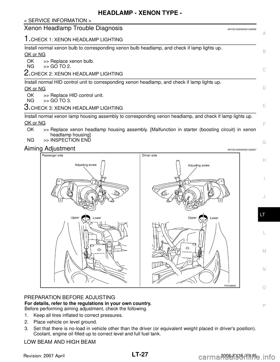
Aiming AdjustmentINFOID:0000000001328287
PREPARATION BEFORE ADJUSTING
For details, refer to the regulations in your own country.
Before performing aiming adjustment, check the following.
1. Keep all tires inflated to correct pressures.
2. Place vehicle on level ground.
3. Set that there is no-load in vehicle other than the driv er (or equivalent weight placed in driver's position).
Coolant, engine oil filled up to correct level and full fuel tank.
LOW BEAM AND HIGH BEAM
PKIC9684E
3AA93ABC3ACD3AC03ACA3AC03AC63AC53A913A773A893A873A873A8E3A773A983AC73AC93AC03AC3
3A893A873A873A8F3A773A9D3AAF3A8A3A8C3A863A9D3AAF3A8B3A8C
Page 3177 of 3924
FRONT FOG LAMPLT-75
< SERVICE INFORMATION >
C
DE
F
G H
I
J
L
M A
B
LT
N
O P
3.CHECK FRONT FOG LAMP GROUND
1. Check continuity between front fog lamp RH harness connector E102 terminal 2 and ground.
2. Check continuity between front fog lamp LH harness connector E45 terminal 2 and ground.
OK or NG
OK >> Replace IPDM E/R. Refer to PG-24, "Removal and
Installation of IPDM E/R".
NG >> Repair harness or connector.
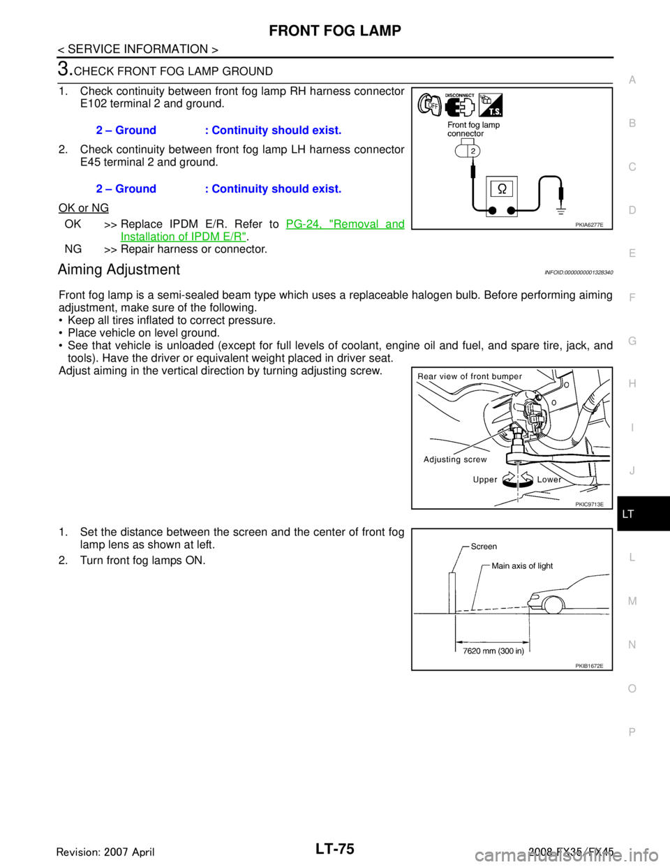
Aiming AdjustmentINFOID:0000000001328340
Front fog lamp is a semi-sealed beam type which uses a replaceable halogen bulb. Before performing aiming
adjustment, make sure of the following.
Keep all tires inflated to correct pressure.
Place vehicle on level ground.
See that vehicle is unloaded (except for full levels of coolant, engine oil and fuel, and spare tire, jack, and tools). Have the driver or equivalent weight placed in driver seat.
Adjust aiming in the vertical direction by turning adjusting screw.
1. Set the distance between the scr een and the center of front fog
lamp lens as shown at left.
2. Turn front fog lamps ON. 2 – Ground : Continuity should exist.
2 – Ground : Continuity should exist.
PKIA6277E
PKIC9713E
PKIB1672E
3AA93ABC3ACD3AC03ACA3AC03AC63AC53A913A773A893A873A873A8E3A773A983AC73AC93AC03AC3
3A893A873A873A8F3A773A9D3AAF3A8A3A8C3A863A9D3AAF3A8B3A8C
Page 3318 of 3924

MA-1
MAINTENANCE
C
DE
F
G H
I
J
K
M
SECTION MA
A
B
MA
N
O P
CONTENTS
MAINTENANCE
SERVICE INFORMATION .. ..........................2
PREPARATION .............................................. .....2
Special Service Tool ........................................... ......2
Commercial Service Tool ..........................................2
GENERAL MAINTENANCE ................................3
Explanation of General Maintenance .................. ......3
PERIODIC MAINTENANCE ................................5
Introduction of Periodic Maintenance .................. ......5
Schedule 1 ................................................................5
Schedule 2 ................................................................7
RECOMMENDED FLUIDS AND LUBRI-
CANTS .................................................................
9
Fluids and Lubricants .......................................... ......9
Engine Oil Recommendation ....................................9
Anti-Freeze Coolant Mixture Ratio ..........................10
ENGINE MAINTENANCE (VQ35DE ENGINE) ....11
Checking Drive Belts ........................................... ....11
Drive Belts Tension Adjustment ..............................11
Changing Engine Coolant .......................................12
Checking Fuel Line .................................................15
Changing Air Cleaner Filter .....................................15
Changing Engine Oil ...............................................15
Changing Oil Filter ..................................................16
Changing Spark Plugs (Platinum-Tipped Type) ......17
Checking EVAP Vapor Line ....................................18
ENGINE MAINTENANCE (VK45DE ENGINE) ....19
Checking Drive Belts ........................................... ....19
Tension Adjustment ................................................19
Changing Engine Coolant .......................................19
Checking Fuel Line .............................................. ....22
Changing Air Cleaner Filter .....................................22
Changing Engine Oil ................................................22
Changing Oil Filter ...................................................23
Changing Spark Plugs (Platinum-Tipped Type) ......24
Checking EVAP Vapor Line .....................................25
CHASSIS AND BODY MAINTENANCE ...........26
Checking Exhaust System ................................... ....26
Checking A/T Fluid ..................................................26
Changing A/T Fluid ..................................................27
Checking Transfer Fluid ..........................................28
Changing Transfer Fluid ..........................................28
Checking Propeller Shaft .........................................29
Checking Differential Gear Oil .................................29
Changing Differential Gear Oil .................................29
Balancing Wheels (Bonding Weight Type) ..............30
Tire Rotation ............................................................31
Checking Brake Fluid Level and Leaks ...................32
Checking Brake Line and Cables ............................32
Changing Brake Fluid ..............................................32
Checking Disc Brake ...............................................32
Checking Steering Gear and Linkage ......................33
Checking Power Steering Fluid and Line ................33
Axle and Suspension Parts .....................................34
Drive Shaft ...............................................................34
Lubricating Locks, Hinges and Hood Latch .............35
Checking Seat Belt, Buckles, Retractors, Anchors
and Adjusters ...........................................................
35
SERVICE DATA AND SPECIFICATIONS
(SDS) .................................................................
37
Standard and Limit ..................................................37
3AA93ABC3ACD3AC03ACA3AC03AC63AC53A913A773A893A873A873A8E3A773A983AC73AC93AC03AC3
3A893A873A873A8F3A773A9D3AAF3A8A3A8C3A863A9D3AAF3A8B3A8C
Page 3322 of 3924
PERIODIC MAINTENANCEMA-5
< SERVICE INFORMATION >
C
DE
F
G H
I
J
K
M A
B
MA
N
O P
PERIODIC MAINTENANCE
Introduction of Periodic MaintenanceINFOID:0000000001328894
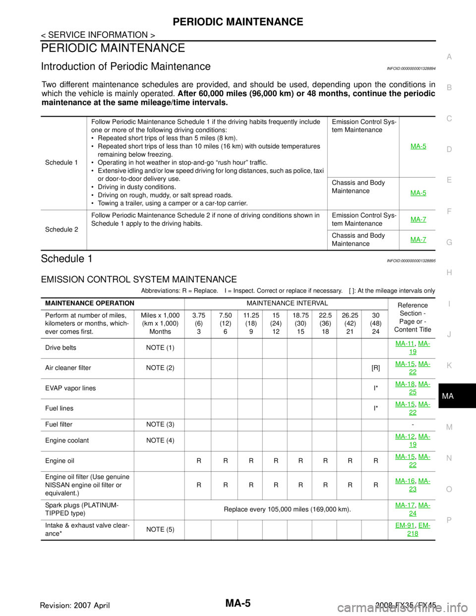
Two different maintenance schedules are provi ded, and should be used, depending upon the conditions in
which the vehicle is mainly operated. After 60,000 miles (96,000 km) or 48 months, continue the periodic
maintenance at the same mileage/time intervals.
Schedule 1INFOID:0000000001328895
EMISSION CONTROL SYSTEM MAINTENANCE
Abbreviations: R = Replace. I = Inspect. Correct or r eplace if necessary. [ ]: At the mileage intervals only
Schedule 1Follow Periodic Maintenance Schedule 1 if the driving habits frequently include
one or more of the following driving conditions:
Repeated short trips of less than 5 miles (8 km).
Repeated short trips of less than 10 miles (16 km) with outside temperatures
remaining below freezing.
Operating in hot weather in stop-and-go “rush hour” traffic.
Extensive idling and/or low speed driving for long distances, such as police, taxi or door-to-door delivery use.
Driving in dusty conditions.
Driving on rough, muddy, or salt spread roads.
Towing a trailer, using a camper or a car-top carrier. Emission Control Sys-
tem Maintenance
MA-5
Chassis and Body
MaintenanceMA-5
Schedule 2Follow Periodic Maintenance Schedule 2 if none of driving conditions shown in
Schedule 1 apply to the driving habits.
Emission Control Sys-
tem Maintenance
MA-7Chassis and Body
Maintenance
MA-7
MAINTENANCE OPERATION
MAINTENANCE INTERVAL
Reference
Section -
Page or -
Content Title
Perform at number of miles,
kilometers or months, which-
ever comes first. Miles x 1,000
(km x 1,000) Months 3.75
(6)3 7.50
(12) 6 11 . 2 5
(18) 9 15
(24) 12 18.75
(30)15 22.5
(36) 18 26.25
(42)21 30
(48) 24
Drive belts NOTE (1) MA-11
,
MA-
19
Air cleaner filter NOTE (2) [R] MA-15,
MA-
22
EVAP vapor lines I*MA-18,
MA-
25
Fuel lines I*MA-15,
MA-
22
Fuel filter NOTE (3) -
Engine coolant NOTE (4) MA-12
,
MA-
19
Engine oil R R R R R R R R MA-15,
MA-
22
Engine oil filter (Use genuine
NISSAN engine oil filter or
equivalent.) R R RRRRR R
MA-16,
MA-
23
Spark plugs (PLATINUM-
TIPPED type) Replace every 105,000 miles (169,000 km).
MA-17,
MA-
24
Intake & exhaust valve clear-
ance* NOTE (5) EM-91,
EM-
218
3AA93ABC3ACD3AC03ACA3AC03AC63AC53A913A773A893A873A873A8E3A773A983AC73AC93AC03AC3
3A893A873A873A8F3A773A9D3AAF3A8A3A8C3A863A9D3AAF3A8B3A8C
Page 3323 of 3924
MA-6
< SERVICE INFORMATION >
PERIODIC MAINTENANCE
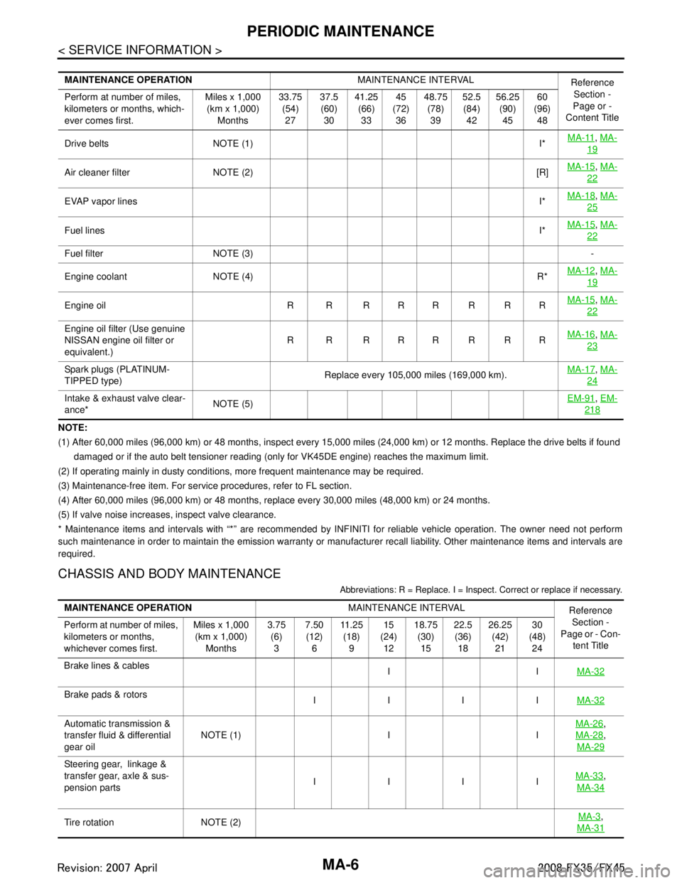
NOTE:
(1) After 60,000 miles (96,000 km) or 48 months, inspect every 15,000 miles (24,000 km) or 12 months. Replace the drive belts if found
damaged or if the auto belt tensioner reading (only for VK45DE engine) reaches the maximum limit.
(2) If operating mainly in dusty conditions, more frequent maintenance may be required.
(3) Maintenance-free item. For service procedures, refer to FL section.
(4) After 60,000 miles (96,000 km) or 48 months, replace every 30,000 miles (48,000 km) or 24 months.
(5) If valve noise increases, inspect valve clearance.
* Maintenance items and intervals with “*” are recommended by INFINITI for reliable vehicle operation. The owner need not perfo rm
such maintenance in order to maintain the emission warranty or manufacturer recall liability. Other maintenance items and inter vals are
required.
CHASSIS AND BODY MAINTENANCE
Abbreviations: R = Replace. I = Inspec t. Correct or replace if necessary.
MAINTENANCE OPERATION MAINTENANCE INTERVAL
Reference
Section -
Page or -
Content Title
Perform at number of miles,
kilometers or months, which-
ever comes first. Miles x 1,000
(km x 1,000) Months 33.75
(54)27 37.5
(60) 30 41.25
(66)33 45
(72) 36 48.75
(78)39 52.5
(84) 42 56.25
(90)45 60
(96) 48
Drive belts NOTE (1) I* MA-11
,
MA-
19
Air cleaner filter NOTE (2) [R] MA-15,
MA-
22
EVAP vapor lines I*MA-18,
MA-
25
Fuel lines I*MA-15,
MA-
22
Fuel filter NOTE (3) -
Engine coolant NOTE (4) R* MA-12
,
MA-
19
Engine oil R R R R R R R R MA-15,
MA-
22
Engine oil filter (Use genuine
NISSAN engine oil filter or
equivalent.) R R RRRRRR
MA-16,
MA-
23
Spark plugs (PLATINUM-
TIPPED type) Replace every 105,000 miles (169,000 km).MA-17,
MA-
24
Intake & exhaust valve clear-
ance* NOTE (5) EM-91,
EM-
218
MAINTENANCE OPERATION MAINTENANCE INTERVAL
Reference
Section -
Page or - Con-
tent Title
Perform at number of miles,
kilometers or months,
whichever comes first. Miles x 1,000
(km x 1,000) Months 3.75
(6)3 7.50
(12) 6 11 . 2 5
(18) 9 15
(24) 12 18.75
(30)15 22.5
(36) 18 26.25
(42)21 30
(48) 24
Brake lines & cables IIMA-32
Brake pads & rotors
IIII MA-32
Automatic transmission &
transfer fluid & differential
gear oilNOTE (1) I I MA-26,
MA-28
,
MA-29
Steering gear, linkage &
transfer gear, axle & sus-
pension parts IIII
MA-33
,
MA-34
Tire rotation NOTE (2) MA-3,
MA-31
3AA93ABC3ACD3AC03ACA3AC03AC63AC53A913A773A893A873A873A8E3A773A983AC73AC93AC03AC3
3A893A873A873A8F3A773A9D3AAF3A8A3A8C3A863A9D3AAF3A8B3A8C