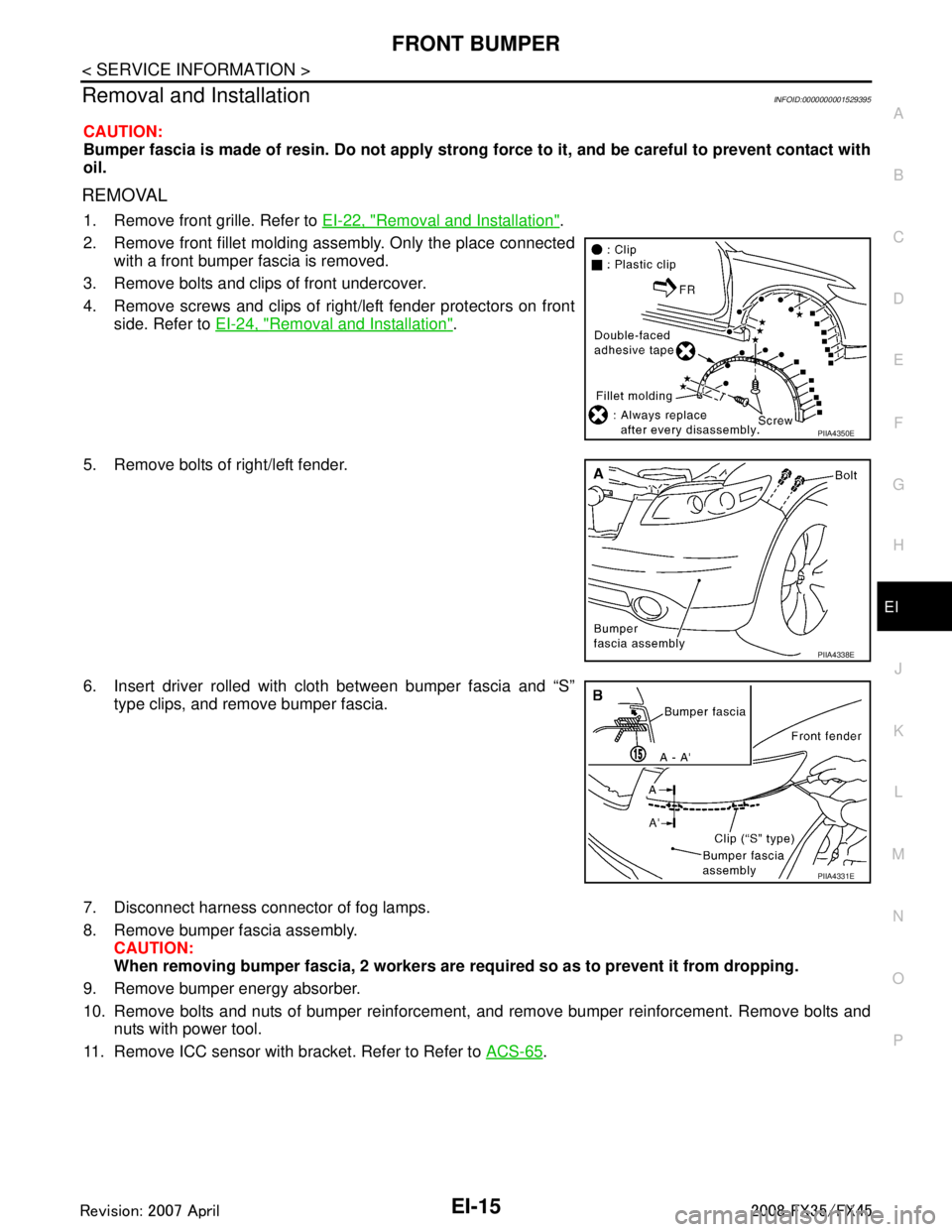
2008 INFINITI FX35 oil type
[x] Cancel search: oil typePage 2160 of 3924
![INFINITI FX35 2008 Service Manual
EC-920
< SERVICE INFORMATION >[VK45DE]
DTC P0420, P0430 THREE
WAY CATALYST FUNCTION
NG >> GO TO 7.
7.CHECK FUNCTION OF IGNITION COIL-II
1. Turn ignition switch OFF.
2. Disconnect spark plug and conn INFINITI FX35 2008 Service Manual
EC-920
< SERVICE INFORMATION >[VK45DE]
DTC P0420, P0430 THREE
WAY CATALYST FUNCTION
NG >> GO TO 7.
7.CHECK FUNCTION OF IGNITION COIL-II
1. Turn ignition switch OFF.
2. Disconnect spark plug and conn](/manual-img/42/57017/w960_57017-2159.png)
EC-920
< SERVICE INFORMATION >[VK45DE]
DTC P0420, P0430 THREE
WAY CATALYST FUNCTION
NG >> GO TO 7.
7.CHECK FUNCTION OF IGNITION COIL-II
1. Turn ignition switch OFF.
2. Disconnect spark plug and connect a known-good spark plug.
3. Crank engine for about three seconds, and recheck whether spark is generated between the spark plug
and the grounded metal portion.
OK or NG
OK >> GO TO 8.
NG >> Check ignition coil, power transistor and their circuits. Refer to EC-1166
.
8.CHECK SPARK PLUG
Check the initial spark plug for fouling, etc.
OK or NG
OK >> Replace malfunctioning spark plug(s) with standard type one(s). For spark plug type, refer to EM-188
.
NG >> 1. Repair or clean spark plug.
2. GO TO 9.
9.CHECK FUNCTION OF IGNITION COIL-III
1. Reconnect the initial spark plugs.
2. Crank engine for about three seconds, and recheck whether spark is generated between the spark plug
and the grounded portion.
OK or NG
OK >> INSPECTION END
NG >> Replace malfunctioning spark plug(s) with standard type one(s). For spark plug type, refer to EM-
188.
10.CHECK FUEL INJECTOR
1. Turn ignition switch OFF.
2. Remove fuel tube assembly. Refer to EM-190
.
Keep fuel hose and all fuel inje ctors connected to fuel tube.
3. Reconnect all fuel injector harness connectors disconnected.
4. Disconnect all ignition coil harness connectors.
5. Turn ignition switch ON. Make sure fuel does not drip from fuel injector.
OK or NG
OK (Does not drip.)>>GO TO 11.
NG (Drips.)>>Replace the fuel injector(s) from which fuel is dripping.
11 .CHECK INTERMITTENT INCIDENT
Refer to EC-717
.
Trouble is fixed.>> INSPECTION END
Trouble is not fixed.>>Replace malfuncti oning three way catalyst assembly.
Spark should be generated.
SEF156I
Spark should be generated.
3AA93ABC3ACD3AC03ACA3AC03AC63AC53A913A773A893A873A873A8E3A773A983AC73AC93AC03AC3
3A893A873A873A8F3A773A9D3AAF3A8A3A8C3A863A9D3AAF3A8B3A8C
Page 2452 of 3924

FRONT BUMPEREI-15
< SERVICE INFORMATION >
C
DE
F
G H
J
K L
M A
B
EI
N
O P
Removal and InstallationINFOID:0000000001529395
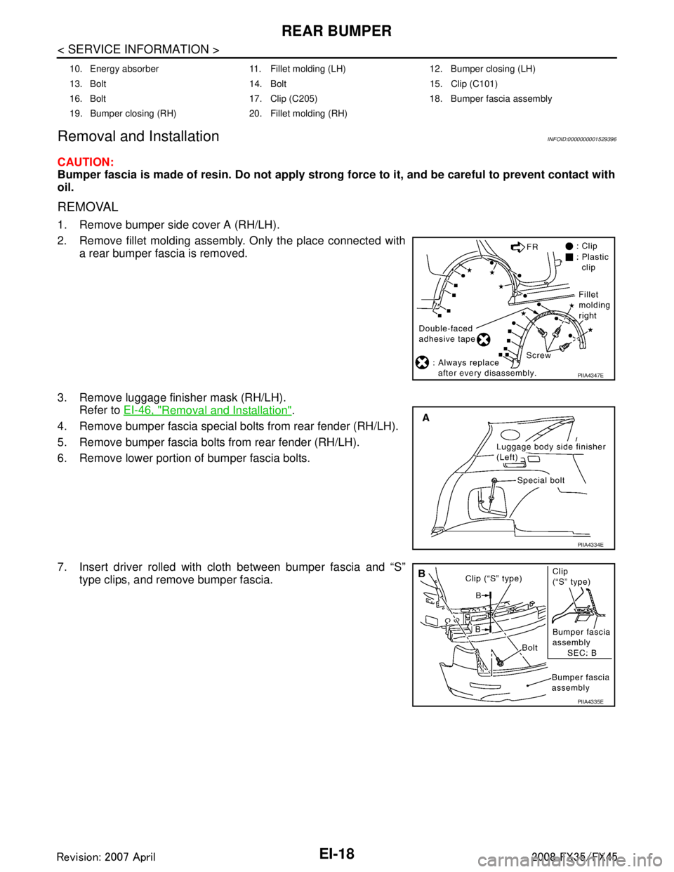
CAUTION:
Bumper fascia is made of resin. Do not apply strong force to it, and be careful to prevent contact with
oil.
REMOVAL
1. Remove front grille. Refer to EI-22, "Removal and Installation".
2. Remove front fillet molding assembly. Only the place connected with a front bumper fascia is removed.
3. Remove bolts and clips of front undercover.
4. Remove screws and clips of right/left fender protectors on front side. Refer to EI-24, "
Removal and Installation".
5. Remove bolts of right/left fender.
6. Insert driver rolled with cloth between bumper fascia and “S” type clips, and remove bumper fascia.
7. Disconnect harness connector of fog lamps.
8. Remove bumper fascia assembly. CAUTION:
When removing bumper fascia, 2 workers are required so as to prevent it from dropping.
9. Remove bumper energy absorber.
10. Remove bolts and nuts of bumper reinforcement, and remove bumper reinforcement. Remove bolts and nuts with power tool.
11. Remove ICC sensor with bracket. Refer to Refer to ACS-65
.
PIIA4350E
PIIA4338E
PIIA4331E
3AA93ABC3ACD3AC03ACA3AC03AC63AC53A913A773A893A873A873A8E3A773A983AC73AC93AC03AC3
3A893A873A873A8F3A773A9D3AAF3A8A3A8C3A863A9D3AAF3A8B3A8C
Page 2455 of 3924

EI-18
< SERVICE INFORMATION >
REAR BUMPER
Removal and Installation
INFOID:0000000001529396
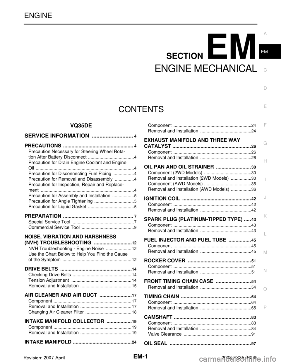
CAUTION:
Bumper fascia is made of resin. Do not apply strong force to it, and be careful to prevent contact with
oil.
REMOVAL
1. Remove bumper side cover A (RH/LH).
2. Remove fillet molding assembly. Only the place connected with a rear bumper fascia is removed.
3. Remove luggage finisher mask (RH/LH). Refer to EI-46, "
Removal and Installation".
4. Remove bumper fascia special bolts from rear fender (RH/LH).
5. Remove bumper fascia bolts from rear fender (RH/LH).
6. Remove lower portion of bumper fascia bolts.
7. Insert driver rolled with cloth between bumper fascia and “S” type clips, and remove bumper fascia.
10. Energy absorber 11. Fillet molding (LH) 12. Bumper closing (LH)
13. Bolt 14. Bolt 15. Clip (C101)
16. Bolt 17. Clip (C205) 18. Bumper fascia assembly
19. Bumper closing (RH) 20. Fillet molding (RH)
PIIA4347E
PIIA4334E
PIIA4335E
3AA93ABC3ACD3AC03ACA3AC03AC63AC53A913A773A893A873A873A8E3A773A983AC73AC93AC03AC3
3A893A873A873A8F3A773A9D3AAF3A8A3A8C3A863A9D3AAF3A8B3A8C
Page 2485 of 3924

EM-1
ENGINE
C
DE
F
G H
I
J
K L
M
SECTION EM
A
EM
N
O P
CONTENTS
ENGINE MECHANICAL
VQ35DE
SERVICE INFORMATION .. ..........................
4
PRECAUTIONS .............................................. .....4
Precaution Necessary for Steering Wheel Rota-
tion After Battery Disconnect ............................... ......
4
Precaution for Drain Engine Coolant and Engine
Oil ..............................................................................
4
Precaution for Disconnecting Fuel Piping .................4
Precaution for Removal and Disassembly ................4
Precaution for Inspection, Repair and Replace-
ment ..........................................................................
4
Precaution for Assembly and Installation ..................5
Precaution for Angle Tightening ................................5
Precaution for Liquid Gasket .....................................5
PREPARATION ...................................................7
Special Service Tool ........................................... ......7
Commercial Service Tool ..........................................9
NOISE, VIBRATION AND HARSHNESS
(NVH) TROUBLESHOOTING ............................
12
NVH Troubleshooting - Engine Noise ................. ....12
Use the Chart Below to Help You Find the Cause
of the Symptom .......................................................
12
DRIVE BELTS ....................................................14
Checking Drive Belts ........................................... ....14
Tension Adjustment ................................................14
Removal and Installation .........................................15
AIR CLEANER AND AIR DUCT ........................17
Component .......................................................... ....17
Removal and Installation .........................................17
Changing Air Cleaner Filter .....................................18
INTAKE MANIFOLD COLLECTOR ...................19
Component .......................................................... ....19
Removal and Installation .........................................19
INTAKE MANIFOLD ...........................................24
Component .......................................................... ....24
Removal and Installation .........................................24
EXHAUST MANIFOLD AND THREE WAY
CATALYST ........................................................
26
Component ..............................................................26
Removal and Installation .........................................26
OIL PAN AND OIL STRAINER .........................30
Component (2WD Models) ......................................30
Removal and Installation (2WD Models) .................30
Component (AWD Models) ......................................35
Removal and Installation (AWD Models) .................36
IGNITION COIL .................................................42
Component ..............................................................42
Removal and Installation .........................................42
SPARK PLUG (PLATINUM-TIPPED TYPE) .....43
Component ..............................................................43
Removal and Installation .........................................43
FUEL INJECTOR AND FUEL TUBE ................45
Component ..............................................................45
Removal and Installation .........................................45
ROCKER COVER .............................................51
Component ..............................................................51
Removal and Installation .........................................51
FRONT TIMING CHAIN CASE .........................54
Removal and Installation .........................................54
TIMING CHAIN ..................................................64
Component .......................................................... ....64
Removal and Installation .........................................65
CAMSHAFT .......................................................83
Component ..............................................................83
Removal and Installation .........................................84
Valve Clearance ......................................................91
OIL SEAL ..........................................................97
3AA93ABC3ACD3AC03ACA3AC03AC63AC53A913A773A893A873A873A8E3A773A983AC73AC93AC03AC3
3A893A873A873A8F3A773A9D3AAF3A8A3A8C3A863A9D3AAF3A8B3A8C
Page 2486 of 3924

EM-2
Removal and Installation of Valve Oil Seal .............97
Removal and Installation of Front Oil Seal .............97
Removal and Installation of Rear Oil Seal ..............98
CYLINDER HEAD ............................................100
On-Vehicle Service .............................................. ..100
Component ............................................................101
Removal and Installation .......................................101
Disassembly and Assembly ...................................105
Inspection After Disassembly ................................107
ENGINE ASSEMBLY .......................................112
Component (2WD Models) .................................. ..112
Removal and Installation (2WD Models) ...............112
Component (AWD Models) ....................................117
Removal and Installation (AWD Models) ...............117
CYLINDER BLOCK .........................................122
Component .......................................................... ..122
Disassembly and Assembly ...................................123
How to Select Piston and Bearing .........................134
Inspection After Disassembly ................................138
SERVICE DATA AND SPECIFICATIONS
(SDS) ................................................................
149
Standard and Limit .............................................. ..149
VK45DE
SERVICE INFORMATION ..........................
160
PRECAUTIONS .............................................. .160
Precaution Necessary for Steering Wheel Rota-
tion After Battery Disconnect ............................... ..
160
Precaution for Drain Engine Coolant and Engine
Oil ..........................................................................
160
Precaution for Disconnecting Fuel Piping ..............160
Precaution for Removal and Disassembly .............160
Precaution for Inspection, Repair and Replace-
ment .......................................................................
160
Precaution for Assembly and Installation ..............161
Parts Requiring Angle Tightening ..........................161
Precaution for Liquid Gasket .................................161
PREPARATION .............................................. .163
Special Service Tool ............................................ ..163
Commercial Service Tool ......................................164
NOISE, VIBRATION AND HARSHNESS
(NVH) TROUBLESHOOTING ..........................
167
NVH Troubleshooting - Engine Noise .................. ..167
Use the Chart Below to Help You Find the Cause
of the Symptom .....................................................
167
ENGINE ROOM COVER ..................................169
Component .......................................................... ..169
Removal and Installation .......................................169
DRIVE BELTS ..................................................170
Component .......................................................... ..170
Checking Drive Belts .............................................170
Tension Adjustment ...............................................170
Removal and Installation ...................................... .170
Component ...........................................................171
Drive Belt Auto Tensioner and Idler Pulley ...........172
AIR CLEANER AND AIR DUCT .......................173
Component .......................................................... .173
Removal and Installation .......................................173
Changing Air Cleaner Filter ...................................174
INTAKE MANIFOLD .........................................175
Component .......................................................... .175
Removal and Installation .......................................176
EXHAUST MANIFOLD AND THREE WAY
CATALYST .......................................................
179
Component .......................................................... .179
Removal and Installation .......................................179
OIL PAN AND OIL STRAINER ........................183
Component .......................................................... .183
Removal and Installation .......................................183
IGNITION COIL .................................................187
Component .......................................................... .187
Removal and Installation .......................................187
SPARK PLUG (PLATINUM-TIPPED TYPE) ....188
Component .......................................................... .188
Removal and Installation .......................................188
FUEL INJECTOR AND FUEL TUBE ................190
Component .......................................................... .190
Removal and Installation .......................................190
ROCKER COVER .............................................196
Component .......................................................... .196
Removal and Installation .......................................196
TIMING CHAIN .................................................199
Component .......................................................... .199
Removal and Installation .......................................200
CAMSHAFT ......................................................211
Component .......................................................... .211
Removal and Installation .......................................211
Valve Clearance ....................................................218
OIL SEAL ..........................................................222
Removal and Installation of Valve Oil Seal ...........222
Removal and Installation of Front Oil Seal ........... .222
Removal and Installation of Rear Oil Seal ............224
CYLINDER HEAD .............................................226
On-Vehicle Service .............................................. .226
Component ...........................................................227
Removal and Installation .......................................227
Disassembly and Assembly ..................................229
Inspection After Disassembly ................................232
ENGINE ASSEMBLY ..................................... ..237
Component .......................................................... .237
Removal and Installation .......................................237
3AA93ABC3ACD3AC03ACA3AC03AC63AC53A913A773A893A873A873A8E3A773A983AC73AC93AC03AC3
3A893A873A873A8F3A773A9D3AAF3A8A3A8C3A863A9D3AAF3A8B3A8C
Page 2497 of 3924
![INFINITI FX35 2008 Service Manual
NOISE, VIBRATION AND HARSHNESS (NVH) TROUBLESHOOTINGEM-13
< SERVICE INFORMATION > [VQ35DE]
C
D
E
F
G H
I
J
K L
M A
EM
NP
O
3. Specify the operating condition of the engine.
4. Check specified noise s INFINITI FX35 2008 Service Manual
NOISE, VIBRATION AND HARSHNESS (NVH) TROUBLESHOOTINGEM-13
< SERVICE INFORMATION > [VQ35DE]
C
D
E
F
G H
I
J
K L
M A
EM
NP
O
3. Specify the operating condition of the engine.
4. Check specified noise s](/manual-img/42/57017/w960_57017-2496.png)
NOISE, VIBRATION AND HARSHNESS (NVH) TROUBLESHOOTINGEM-13
< SERVICE INFORMATION > [VQ35DE]
C
D
E
F
G H
I
J
K L
M A
EM
NP
O
3. Specify the operating condition of the engine.
4. Check specified noise source.
If necessary, repair or replace these parts.
A: Closely related B: Related C: Sometimes related —: Not related Location
of noise Type of
noise Operating condition of engine
Source of noise Check item Refer-
ence page
Before
warm- up After
warm- up When
start- ing When
idling When
racing While
driving
Top of en-
gine
Rocker
cover
Cylinder
head Ticking or
clicking
CA—AB— Tappet
noiseValve clearance
EM-91
Rattle C A — A B C Camshaft
bearing
noiseCamshaft runout
Camshaft journal oil
clearance EM-84EM-84
Crank-
shaft pul-
ley
Cylinder
block
(Side of
engine)
Oil panSlap or
knock
—A—B B— Piston pin
noisePiston to piston pin oil
clearance
Connecting rod bushing
oil clearance EM-138
EM-138
Slap or
rap
A——B B A Piston
slap noisePiston to cylinder bore
clearance
Piston ring side clear-
ance
Piston ring end gap
Connecting rod bend
and torsion EM-138EM-138
EM-138
EM-138
Knock A B C B B B
Connect-
ing rod
bearing
noiseConnecting rod bushing
oil clearance
Connecting rod bearing
oil clearance EM-138EM-138
Knock A B — A B C
Main bear-
ing noiseMain bearing oil clear-
ance
Crankshaft runout EM-138
EM-138
Front of
engine
Timing
chain caseTapping or
ticking
AA—BBB Timing
chain and
timing
chain ten-
sioner
noiseTiming chain cracks
and wear
Timing chain tensioner
operation
EM-65
EM-64
Front of
engineSqueak-
ing or fizz-
ing
AB—B—C Drive belts
(Sticking
or slip-
ping)Drive belts deflection
EM-14
CreakingABABAB Drive belts
(Slipping)Idler pulley bearing op-
eration
Squall
Creak AB—BAB Water
pump
noiseWater pump operation
CO-22
3AA93ABC3ACD3AC03ACA3AC03AC63AC53A913A773A893A873A873A8E3A773A983AC73AC93AC03AC3
3A893A873A873A8F3A773A9D3AAF3A8A3A8C3A863A9D3AAF3A8B3A8C
Page 2518 of 3924
![INFINITI FX35 2008 Service Manual
EM-34
< SERVICE INFORMATION >[VQ35DE]
OIL PAN AND OIL STRAINER
Tighten mounting bolts in numerical order as shown in the fig-
ure.
There are two types of mounting bolts. Refer to the following
fo INFINITI FX35 2008 Service Manual
EM-34
< SERVICE INFORMATION >[VQ35DE]
OIL PAN AND OIL STRAINER
Tighten mounting bolts in numerical order as shown in the fig-
ure.
There are two types of mounting bolts. Refer to the following
fo](/manual-img/42/57017/w960_57017-2517.png)
EM-34
< SERVICE INFORMATION >[VQ35DE]
OIL PAN AND OIL STRAINER
Tighten mounting bolts in numerical order as shown in the fig-
ure.
There are two types of mounting bolts. Refer to the following
for locating bolts.
f. Tighten transmission joint bolts. Refer to AT-241, "
Removal and Installation (2WD Models)".
2. Install oil strainer to oil pump.
3. Install oil pan (lower) as follows:
a. Use scraper to remove old liquid gasket from mating surfaces. Also remove old liquid gasket from mating surface of oil pan(upper).
Remove old liquid gasket from the bolt holes and thread.
CAUTION:
Do not scratch or damage the mating surfaces when clean-
ing off old liquid gasket.
b. Apply a continuous bead of liquid gasket with the tube presser (commercial service tool) to the oil pan (lower) as shown in the
figure.
Use Genuine RTV Silicone Seal ant or equivalent. Refer to
GI-44, "
Recommended Chemical Product and Sealant".
CAUTION:
Attaching should be done with in 5 minutes after coating.
c. Install oil pan (lower). M8
× 100 mm (3.94 in) : 5, 7, 8, 11
M8 × 25 mm (0.98 in) : Except the above
PBIC0783E
SEM958F
PBIC2657E
3AA93ABC3ACD3AC03ACA3AC03AC63AC53A913A773A893A873A873A8E3A773A983AC73AC93AC03AC3
3A893A873A873A8F3A773A9D3AAF3A8A3A8C3A863A9D3AAF3A8B3A8C
Page 2524 of 3924
![INFINITI FX35 2008 Service Manual
EM-40
< SERVICE INFORMATION >[VQ35DE]
OIL PAN AND OIL STRAINER
d. Apply a continuous bead of liquid gasket with the tube presser
(commercial service tool) to the cylinder block mating surface of
oil INFINITI FX35 2008 Service Manual
EM-40
< SERVICE INFORMATION >[VQ35DE]
OIL PAN AND OIL STRAINER
d. Apply a continuous bead of liquid gasket with the tube presser
(commercial service tool) to the cylinder block mating surface of
oil](/manual-img/42/57017/w960_57017-2523.png)
EM-40
< SERVICE INFORMATION >[VQ35DE]
OIL PAN AND OIL STRAINER
d. Apply a continuous bead of liquid gasket with the tube presser
(commercial service tool) to the cylinder block mating surface of
oil pan (upper) to a limited portion as shown in the figure.
Use Genuine RTV Silicone Seal ant or equivalent. Refer to
GI-44, "
Recommended Chemical Product and Sealant".
CAUTION:
For bolt holes with marks (5 locations), apply liquid
gasket outside the holes.
Apply a bead of 4.5 to 5.5 mm (0.177 to 0.217 in) in diame-
ter to area “A”.
Attaching should be done wit hin 5 minutes after coating.
e. Install oil pan (upper). CAUTION:
Install avoiding misalignment of both oil pan gasket and O-rings.
Tighten mounting bolts in numerical order as shown in the fig- ure.
There are two types of mounting bolts. Refer to the following
for locating bolts.
f. Tighten transmission joint bolts. Refer to AT-241, "
Removal and Installation (2WD Models)".
3. Install oil strainer to oil pump.
4. Install oil pan (lower) as follows:
a. Use scraper to remove old liquid gasket from mating surfaces. Also remove old liquid gasket from mating surface of oil pan(upper).
Remove old liquid gasket from the bolt holes and thread.
CAUTION:
Do not scratch or damage the mating surfaces when clean-
ing off old liquid gasket. M8
× 100 mm (3.94 in) : 5, 7, 8, 11
M8 × 25 mm (0.98 in) : Except the above
PBIC2300E
PBIC0783E
SEM958F
3AA93ABC3ACD3AC03ACA3AC03AC63AC53A913A773A893A873A873A8E3A773A983AC73AC93AC03AC3
3A893A873A873A8F3A773A9D3AAF3A8A3A8C3A863A9D3AAF3A8B3A8C