2008 INFINITI FX35 light
[x] Cancel search: lightPage 3766 of 3924
TROUBLE DIAGNOSISSRS-29
< SERVICE INFORMATION >
C
DE
F
G
I
J
K L
M A
B
SRS
N
O P
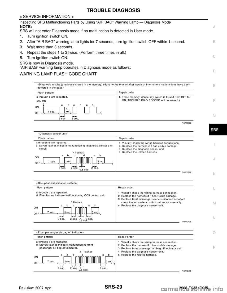
Inspecting SRS Malfunctioning Parts by Using “AIR BAG” Warning Lamp — Diagnosis Mode
NOTE:
SRS will not enter Diagnosis mode if no malfunction is detected in User mode.
1. Turn ignition switch ON.
2. After “AIR BAG” warning lamp lights for 7 seconds, turn ignition switch OFF within 1 second.
3. Wait more than 3 seconds.
4. Repeat the steps 1 to 3 twice. (Perform three times in all.)
5. Turn ignition switch ON.
SRS is now in Diagnosis mode.
“AIR BAG” warning lamp operates in Diagnosis mode as follows:
WARNING LAMP FLASH CODE CHART
PHIA0532E
SHIA0028E
PHIA1242E
PHIA1243E
3AA93ABC3ACD3AC03ACA3AC03AC63AC53A913A773A893A873A873A8E3A773A983AC73AC93AC03AC3
3A893A873A873A8F3A773A9D3AAF3A8A3A8C3A863A9D3AAF3A8B3A8C
Page 3773 of 3924
SRS-36
< SERVICE INFORMATION >
SPIRAL CABLE
SPIRAL CABLE
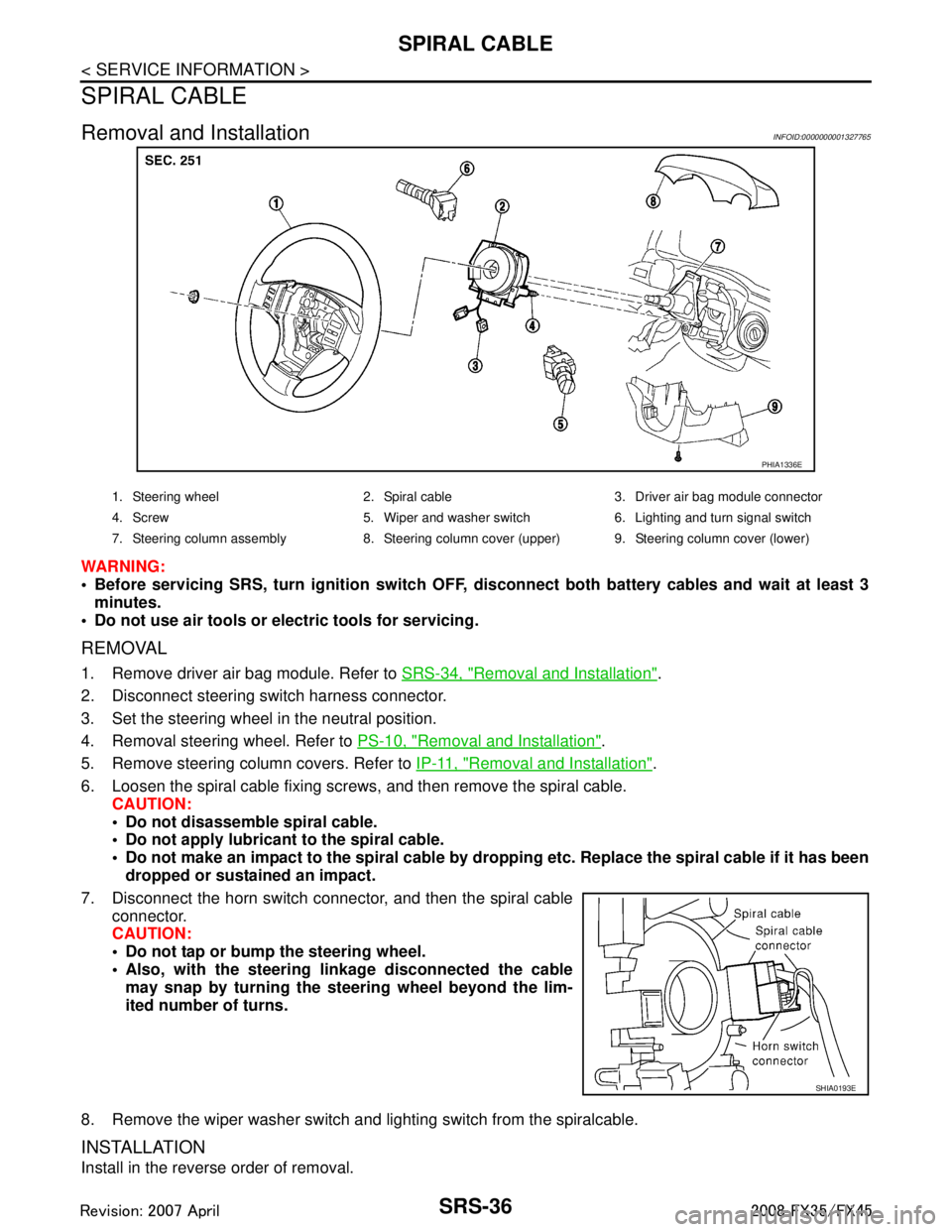
Removal and InstallationINFOID:0000000001327765
WARNING:
Before servicing SRS, turn ignition switch OFF, disconnect both ba ttery cables and wait at least 3
minutes.
Do not use air tools or el ectric tools for servicing.
REMOVAL
1. Remove driver air bag module. Refer to SRS-34, "Removal and Installation".
2. Disconnect steering switch harness connector.
3. Set the steering wheel in the neutral position.
4. Removal steering wheel. Refer to PS-10, "
Removal and Installation".
5. Remove steering column covers. Refer to IP-11, "
Removal and Installation".
6. Loosen the spiral cable fixing screws, and then remove the spiral cable. CAUTION:
Do not disassemble spiral cable.
Do not apply lubricant to the spiral cable.
Do not make an impact to the spiral cable by dro pping etc. Replace the spiral cable if it has been
dropped or sustained an impact.
7. Disconnect the horn switch connec tor, and then the spiral cable
connector.
CAUTION:
Do not tap or bump the steering wheel.
Also, with the steering li nkage disconnected the cable
may snap by turning the st eering wheel beyond the lim-
ited number of turns.
8. Remove the wiper washer switch and lighting switch from the spiralcable.
INSTALLATION
Install in the reverse order of removal.
PHIA1336E
1. Steering wheel 2. Spiral cable 3. Driver air bag module connector
4. Screw 5. Wiper and washer switch 6. Lighting and turn signal switch
7. Steering column assembly 8. Steering column cover (upper) 9. Steering column cover (lower)
SHIA0193E
3AA93ABC3ACD3AC03ACA3AC03AC63AC53A913A773A893A873A873A8E3A773A983AC73AC93AC03AC3
3A893A873A873A8F3A773A9D3AAF3A8A3A8C3A863A9D3AAF3A8B3A8C
Page 3806 of 3924
TF-20
< SERVICE INFORMATION >
TROUBLE DIAGNOSIS
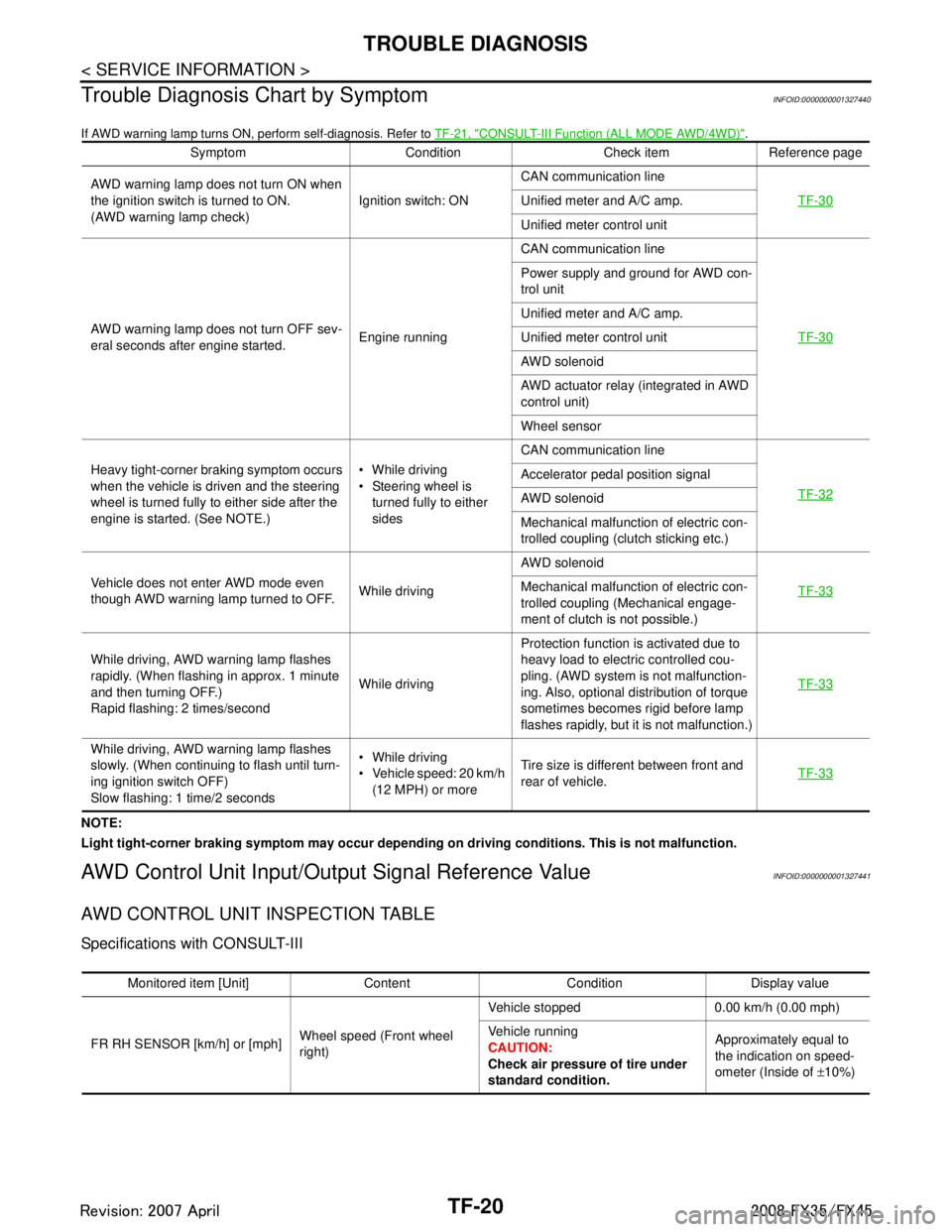
Trouble Diagnosis Chart by Symptom
INFOID:0000000001327440
If AWD warning lamp turns ON, perform self-diagnosis. Refer to TF-21, "CONSULT-III Function (ALL MODE AWD/4WD)".
NOTE:
Light tight-corner braking symptom may occur depending on driving conditions. This is not malfunction.
AWD Control Unit Input/Output Signal Reference ValueINFOID:0000000001327441
AWD CONTROL UNIT INSPECTION TABLE
Specifications with CONSULT-III
Symptom Condition Check item Reference page
AWD warning lamp does not turn ON when
the ignition switch is turned to ON.
(AWD warning lamp check) Ignition switch: ONCAN communication line
TF-30
Unified meter and A/C amp.
Unified meter control unit
AWD warning lamp does not turn OFF sev-
eral seconds after engine started. Engine runningCAN communication line
TF-30
Power supply and ground for AWD con-
trol unit
Unified meter and A/C amp.
Unified meter control unit
AWD solenoid
AWD actuator relay (integrated in AWD
control unit)
Wheel sensor
Heavy tight-corner braking symptom occurs
when the vehicle is driven and the steering
wheel is turned fully to either side after the
engine is started. (See NOTE.) While driving
Steering wheel is
turned fully to either
sides CAN communication line
TF-32
Accelerator pedal position signal
AWD solenoid
Mechanical malfunction of electric con-
trolled coupling (clutch sticking etc.)
Vehicle does not enter AWD mode even
though AWD warning lamp turned to OFF. While drivingAWD solenoid
TF-33
Mechanical malfunction of electric con-
trolled coupling (Mechanical engage-
ment of clutch is not possible.)
While driving, AWD warning lamp flashes
rapidly. (When flashing in approx. 1 minute
and then turning OFF.)
Rapid flashing: 2 times/second While drivingProtection function is activated due to
heavy load to electric controlled cou-
pling. (AWD system is not malfunction-
ing. Also, optional distribution of torque
sometimes becomes rigid before lamp
flashes rapidly, but it is not malfunction.) TF-33
While driving, AWD warning lamp flashes
slowly. (When continuing to flash until turn-
ing ignition switch OFF)
Slow flashing: 1 time/2 seconds While driving
Vehicle speed: 20 km/h
(12 MPH) or more Tire size is different between front and
rear of vehicle.
TF-33
Monitored item [Unit] Content Condition Display value
FR RH SENSOR [km/h] or [mph] Wheel speed (Front wheel
right)Vehicle stopped 0.00 km/h (0.00 mph)
Vehicle running
CAUTION:
Check air pressure of tire under
standard condition.
Approximately equal to
the indication on speed-
ometer (Inside of
±10%)
3AA93ABC3ACD3AC03ACA3AC03AC63AC53A913A773A893A873A873A8E3A773A983AC73AC93AC03AC3
3A893A873A873A8F3A773A9D3AAF3A8A3A8C3A863A9D3AAF3A8B3A8C
Page 3818 of 3924
TF-32
< SERVICE INFORMATION >
TROUBLE DIAGNOSIS FOR SYMPTOMS
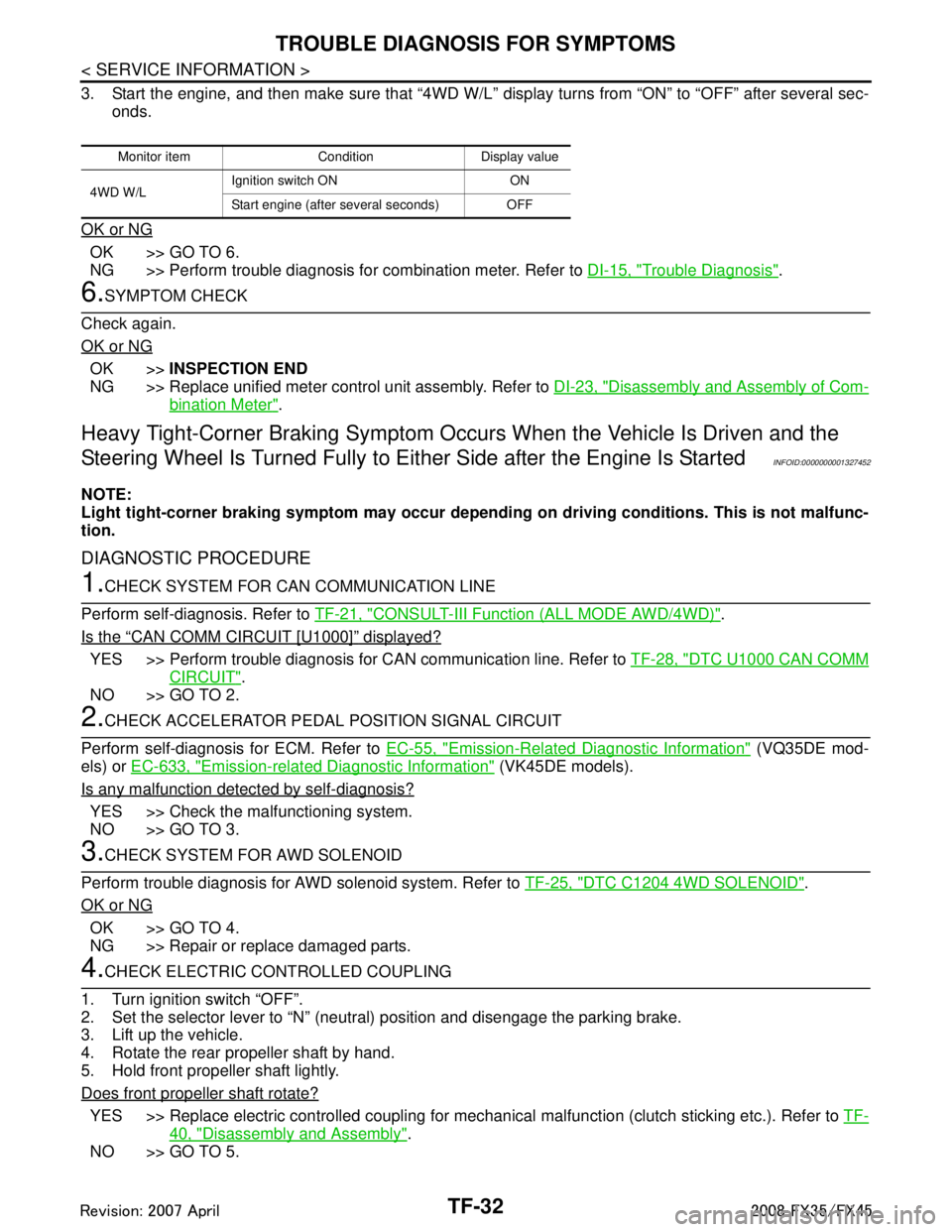
3. Start the engine, and then make sure that “4WD W/L” display turns from “ON” to “OFF” after several sec-
onds.
OK or NG
OK >> GO TO 6.
NG >> Perform trouble diagnosis for combination meter. Refer to DI-15, "
Trouble Diagnosis".
6.SYMPTOM CHECK
Check again.
OK or NG
OK >> INSPECTION END
NG >> Replace unified meter control unit assembly. Refer to DI-23, "
Disassembly and Assembly of Com-
bination Meter".
Heavy Tight-Corner Braking Symptom Occurs When the Vehicle Is Driven and the
Steering Wheel Is Turned Fu lly to Either Side after the Engine Is Started
INFOID:0000000001327452
NOTE:
Light tight-corner braking symptom may occur depending on driving conditions. This is not malfunc-
tion.
DIAGNOSTIC PROCEDURE
1.CHECK SYSTEM FOR CAN COMMUNICATION LINE
Perform self-diagnosis. Refer to TF-21, "
CONSULT-III Function (ALL MODE AWD/4WD)".
Is the
“CAN COMM CIRCUIT [U1000]” displayed?
YES >> Perform trouble diagnosis for CAN communication line. Refer to TF-28, "DTC U1000 CAN COMM
CIRCUIT".
NO >> GO TO 2.
2.CHECK ACCELERATOR PEDAL POSITION SIGNAL CIRCUIT
Perform self-diagnosis for ECM. Refer to EC-55, "
Emission-Related Diagnostic Information" (VQ35DE mod-
els) or EC-633, "
Emission-related Diagnostic Information" (VK45DE models).
Is any malfunction detec ted by self-diagnosis?
YES >> Check the malfunctioning system.
NO >> GO TO 3.
3.CHECK SYSTEM FOR AWD SOLENOID
Perform trouble diagnosis for AWD solenoid system. Refer to TF-25, "
DTC C1204 4WD SOLENOID".
OK or NG
OK >> GO TO 4.
NG >> Repair or replace damaged parts.
4.CHECK ELECTRIC CONTROLLED COUPLING
1. Turn ignition switch “OFF”.
2. Set the selector lever to “N” (neutral) position and disengage the parking brake.
3. Lift up the vehicle.
4. Rotate the rear propeller shaft by hand.
5. Hold front propeller shaft lightly.
Does front propeller shaft rotate?
YES >> Replace electric controlled coupling for mec hanical malfunction (clutch sticking etc.). Refer to TF-
40, "Disassembly and Assembly".
NO >> GO TO 5.
Monitor item Condition Display value
4WD W/L Ignition switch ON ON
Start engine (after several seconds) OFF
3AA93ABC3ACD3AC03ACA3AC03AC63AC53A913A773A893A873A873A8E3A773A983AC73AC93AC03AC3
3A893A873A873A8F3A773A9D3AAF3A8A3A8C3A863A9D3AAF3A8B3A8C
Page 3885 of 3924
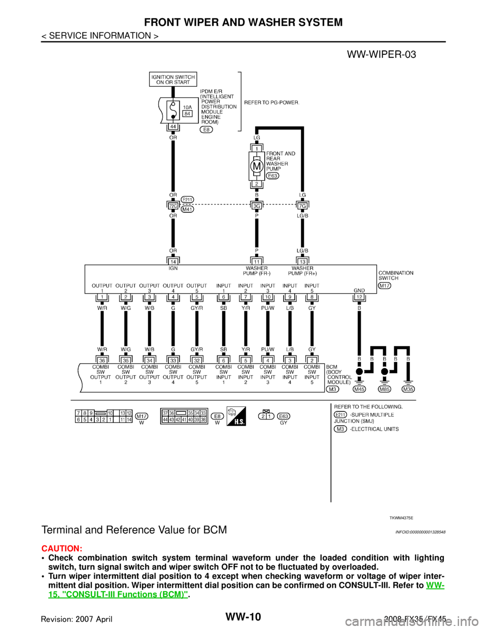
WW-10
< SERVICE INFORMATION >
FRONT WIPER AND WASHER SYSTEM
Terminal and Reference Value for BCM
INFOID:0000000001328548
CAUTION:
Check combination switch system terminal waveform under the loaded condition with lighting
switch, turn signal switch and wiper switch OFF not to be fluctuated by overloaded.
Turn wiper intermittent dial posi tion to 4 except when checking wavef orm or voltage of wiper inter-
mittent dial position. Wiper intermittent dial position can be confirmed on CONSULT-III. Refer to WW-
15, "CONSULT-III Functions (BCM)".
TKWM4375E
3AA93ABC3ACD3AC03ACA3AC03AC63AC53A913A773A893A873A873A8E3A773A983AC73AC93AC03AC3
3A893A873A873A8F3A773A9D3AAF3A8A3A8C3A863A9D3AAF3A8B3A8C
Page 3886 of 3924
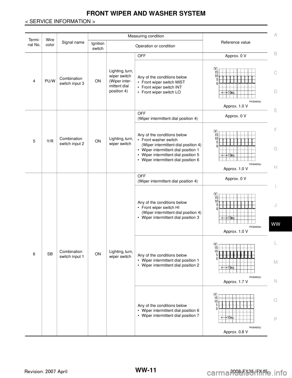
FRONT WIPER AND WASHER SYSTEMWW-11
< SERVICE INFORMATION >
C
DE
F
G H
I
J
L
M A
B
WW
N
O P
Te r m i -
nal No. Wire
color Signal name Measuring condition
Reference value
Ignition
switch Operation or condition
4PU/W Combination
switch input 3
ONLighting, turn,
wiper switch
(Wiper inter-
mittent dial
position 4) OFF Approx. 0 V
Any of the conditions below
Front wiper switch MIST
Front wiper switch INT
Front wiper switch LO
Approx. 1.0 V
5Y/R Combination
switch input 2 ON
Lighting, turn,
wiper switch OFF
(Wiper intermittent dial position 4)
Approx. 0 V
Any of the conditions below
Front washer switch (Wiper intermittent dial position 4)
Wiper intermittent dial position 1
Wiper intermittent dial position 5
Wiper intermittent dial position 6
Approx. 1.0 V
6SB Combination
switch input 1 ON
Lighting, turn,
wiper switch OFF
(Wiper intermittent dial position 4)
Approx. 0 V
Any of the conditions below
Front wiper switch HI (Wiper intermittent dial position 4)
Wiper intermittent dial position 3
Approx. 1.0 V
Any of the conditions below
Wiper intermittent dial position 1
Wiper intermittent dial position 2 Approx. 1.7 V
Any of the conditions below
Wiper intermittent dial position 6
Wiper intermittent dial position 7 Approx. 0.8 V
PKIB4959J
PKIB4959J
PKIB4959J
PKIB4952J
PKIB4955J
3AA93ABC3ACD3AC03ACA3AC03AC63AC53A913A773A893A873A873A8E3A773A983AC73AC93AC03AC3
3A893A873A873A8F3A773A9D3AAF3A8A3A8C3A863A9D3AAF3A8B3A8C
Page 3887 of 3924
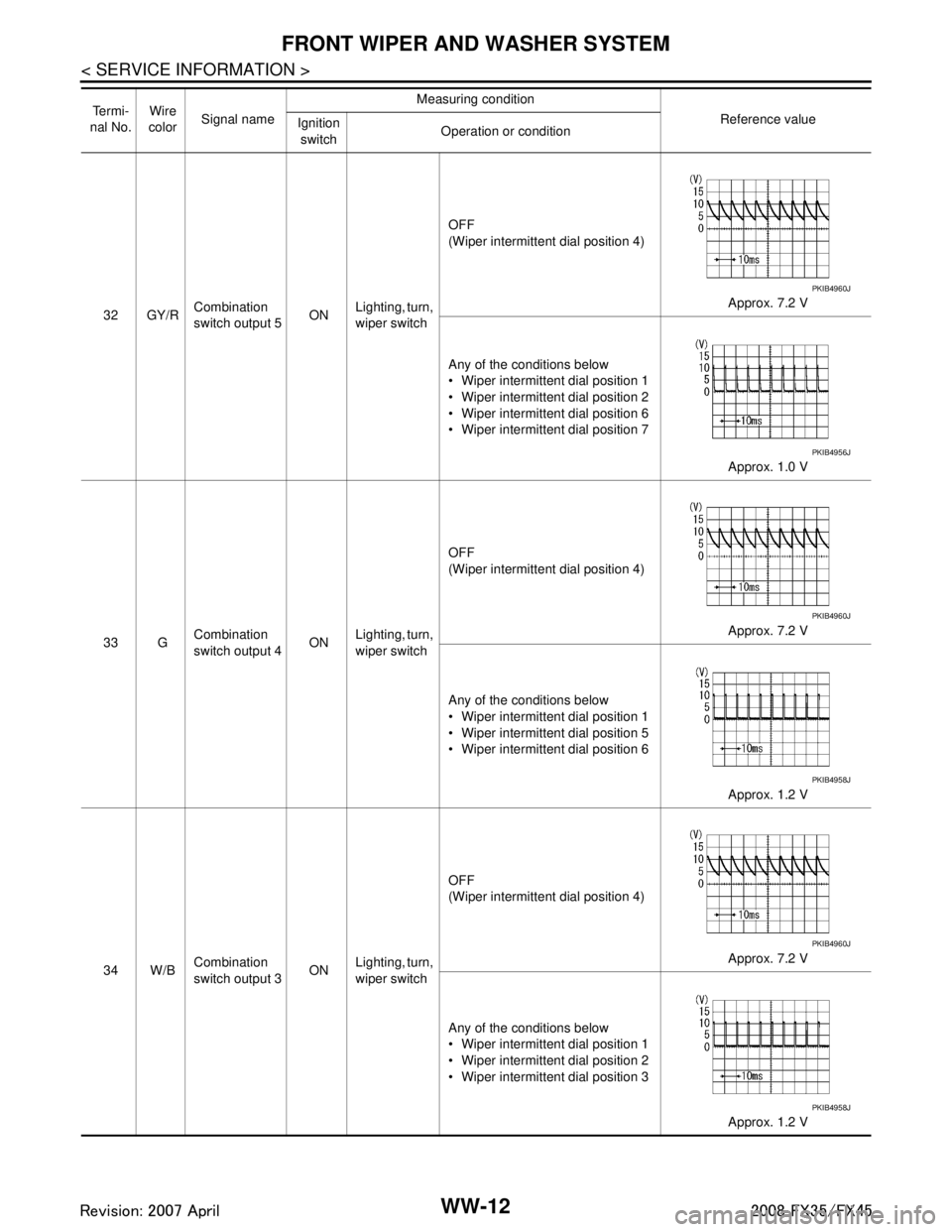
WW-12
< SERVICE INFORMATION >
FRONT WIPER AND WASHER SYSTEM
32 GY/RCombination
switch output 5 ON
Lighting, turn,
wiper switch OFF
(Wiper intermittent dial position 4)
Approx. 7.2 V
Any of the conditions below
Wiper intermittent dial position 1
Wiper intermittent dial position 2
Wiper intermittent dial position 6
Wiper intermittent dial position 7 Approx. 1.0 V
33 G Combination
switch output 4
ONLighting, turn,
wiper switch OFF
(Wiper intermittent dial position 4)
Approx. 7.2 V
Any of the conditions below
Wiper intermittent dial position 1
Wiper intermittent dial position 5
Wiper intermittent dial position 6 Approx. 1.2 V
34 W/B Combination
switch output 3 ONLighting, turn,
wiper switch OFF
(Wiper intermittent dial position 4)
Approx. 7.2 V
Any of the conditions below
Wiper intermittent dial position 1
Wiper intermittent dial position 2
Wiper intermittent dial position 3 Approx. 1.2 V
Te r m i -
nal No. Wire
color Signal name Measuring condition
Reference value
Ignition
switch Operation or condition
PKIB4960J
PKIB4956J
PKIB4960J
PKIB4958J
PKIB4960J
PKIB4958J
3AA93ABC3ACD3AC03ACA3AC03AC63AC53A913A773A893A873A873A8E3A773A983AC73AC93AC03AC3
3A893A873A873A8F3A773A9D3AAF3A8A3A8C3A863A9D3AAF3A8B3A8C
Page 3888 of 3924
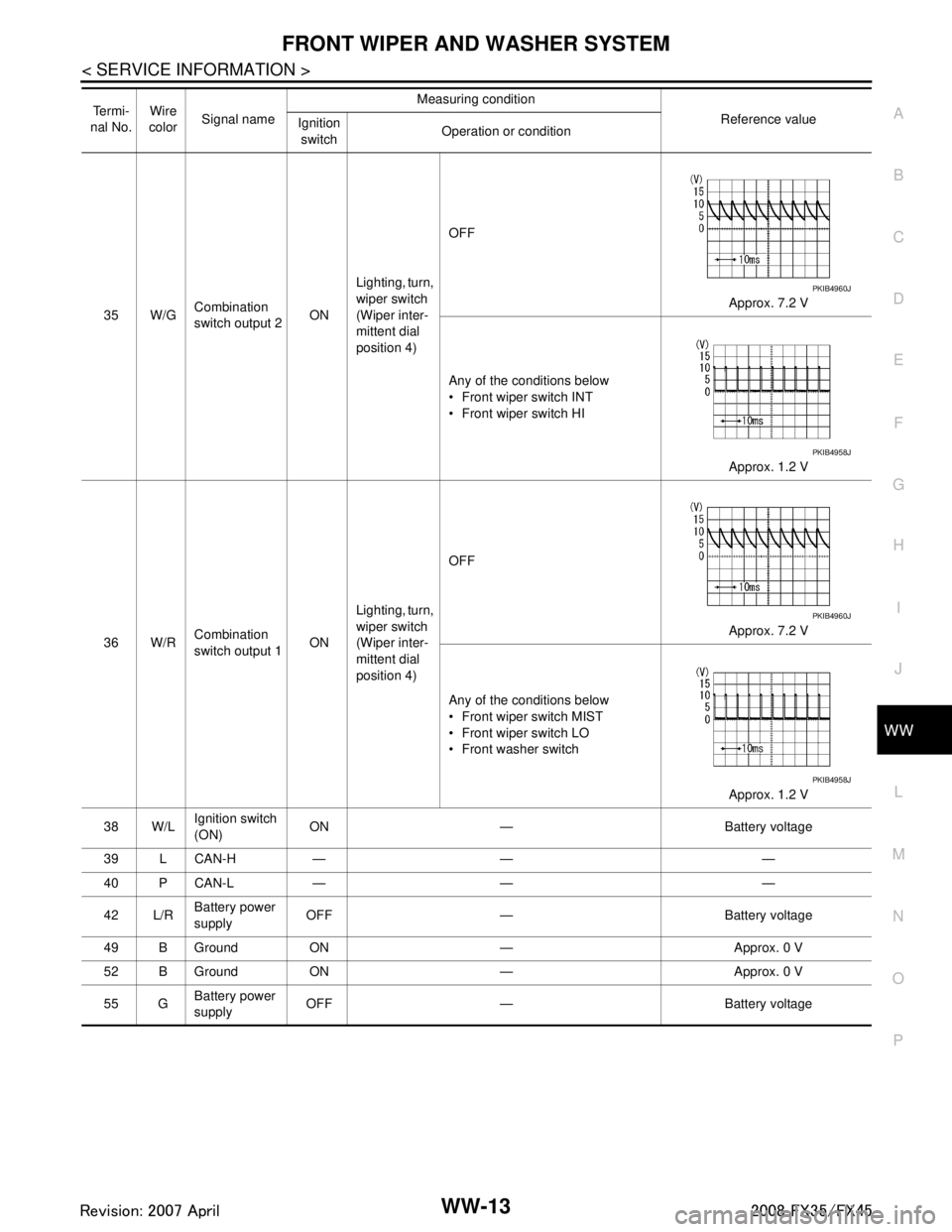
FRONT WIPER AND WASHER SYSTEMWW-13
< SERVICE INFORMATION >
C
DE
F
G H
I
J
L
M A
B
WW
N
O P
35 W/G Combination
switch output 2 ONLighting, turn,
wiper switch
(Wiper inter-
mittent dial
position 4) OFF
Approx. 7.2 V
Any of the conditions below
Front wiper switch INT
Front wiper switch HI Approx. 1.2 V
36 W/R Combination
switch output 1
ONLighting, turn,
wiper switch
(Wiper inter-
mittent dial
position 4) OFF
Approx. 7.2 V
Any of the conditions below
Front wiper switch MIST
Front wiper switch LO
Front washer switch Approx. 1.2 V
38 W/L Ignition switch
(ON) ON — Battery voltage
39 L CAN-H — — —
40 P CAN-L — — —
42 L/R Battery power
supply
OFF — Battery voltage
49 B Ground ON — Approx. 0 V
52 B Ground ON — Approx. 0 V
55 G Battery power
supply OFF — Battery voltage
Te r m i -
nal No. Wire
color Signal name Measuring condition
Reference value
Ignition
switch Operation or condition
PKIB4960J
PKIB4958J
PKIB4960J
PKIB4958J
3AA93ABC3ACD3AC03ACA3AC03AC63AC53A913A773A893A873A873A8E3A773A983AC73AC93AC03AC3
3A893A873A873A8F3A773A9D3AAF3A8A3A8C3A863A9D3AAF3A8B3A8C