2008 INFINITI FX35 light
[x] Cancel search: lightPage 3207 of 3924
COMBINATION SWITCHLT-105
< SERVICE INFORMATION >
C
DE
F
G H
I
J
L
M A
B
LT
N
O P
Example: When the HI BEAM switch is malfuncti oning, confirm that “TURN RH”, “HEAD LAMP 1” and
“LIGHT SW 1 ST” in System 5, to which the HI BEAM switch belongs, turn ON-OFF normally.
Without CONSULT-III
Operating combination switch, and confirm that other switches in malfunctioning system operate normally.
Example: When the HI BEAM switch is malfunctioni ng, confirm that “TURN RH”, “HEAD LAMP 1” and “LIGHT
SW 1 ST” in System 5, to which HI BE AM switch belongs, turn ON-OFF normally.
Check results
Other switches in malfunctioning system operate normally.>>Replace light ing switch or wiper switch.
Other switches in malfunctioning syst em do not operate normally.>>GO TO 3.
3.CHECK HARNESS BETWEEN COMB INATION SWITCH AND BCM
1. Turn ignition switch OFF.
2. Disconnect BCM connector and combination switch connector.
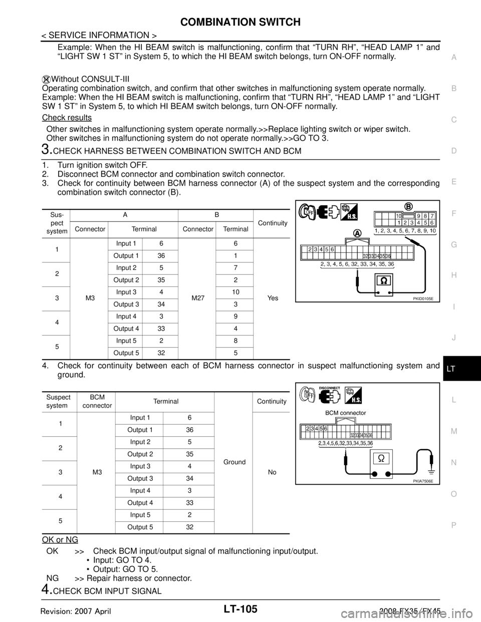
3. Check for continuity between BCM harness connecto r (A) of the suspect system and the corresponding
combination switch connector (B).
4. Check for continuity between each of BCM harne ss connector in suspect malfunctioning system and
ground.
OK or NG
OK >> Check BCM input/output signal of malfunctioning input/output.
Input: GO TO 4.
Output: GO TO 5.
NG >> Repair harness or connector.
4.CHECK BCM INPUT SIGNAL
Sus-
pect
system AB
Continuity
Connector Terminal Connector Terminal
1
M3 Input 1 6
M276
Ye s
Output 1 36 1
2 Input 2 5 7
Output 2 35 2
3 Input 3 4 10
Output 3 34 3
4 Input 4 3 9
Output 4 33 4
5 Input 5 2 8
Output 5 32 5
Suspect
system BCM
connector Te r m i n a l
GroundContinuity
1
M3 Input 1 6
No
Output 1 36
2 Input 2 5
Output 2 35
3 Input 3 4
Output 3 34
4 Input 4 3
Output 4 33
5 Input 5 2
Output 5 32
PKID0105E
PKIA7506E
3AA93ABC3ACD3AC03ACA3AC03AC63AC53A913A773A893A873A873A8E3A773A983AC73AC93AC03AC3
3A893A873A873A8F3A773A9D3AAF3A8A3A8C3A863A9D3AAF3A8B3A8C
Page 3208 of 3924
LT-106
< SERVICE INFORMATION >
COMBINATION SWITCH
1. Connect BCM connector and combination switch connector.
2. Turn ignition switch ON.
3. Lighting switch and wiper switch are turned OFF.
4. Set wiper intermittent dial position 4.
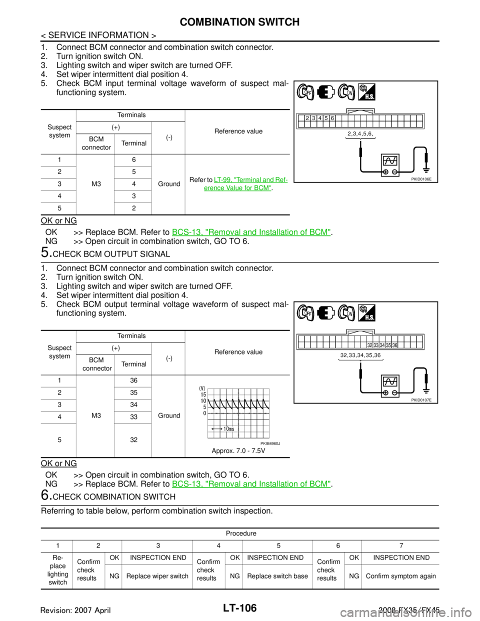
5. Check BCM input terminal voltage waveform of suspect mal-functioning system.
OK or NG
OK >> Replace BCM. Refer to BCS-13, "Removal and Installation of BCM".
NG >> Open circuit in combination switch, GO TO 6.
5.CHECK BCM OUTPUT SIGNAL
1. Connect BCM connector and combination switch connector.
2. Turn ignition switch ON.
3. Lighting switch and wiper switch are turned OFF.
4. Set wiper intermittent dial position 4.
5. Check BCM output terminal voltage waveform of suspect mal- functioning system.
OK or NG
OK >> Open circuit in combination switch, GO TO 6.
NG >> Replace BCM. Refer to BCS-13, "
Removal and Installation of BCM".
6.CHECK COMBINATION SWITCH
Referring to table below, perform combination switch inspection.
Suspect system Te r m i n a l s
Reference value
(+)
(-)
BCM
connector Te r m i n a l
1
M3 6
Ground Refer to
LT- 9 9 , "
Terminal and Ref-
erence Value for BCM".
25
34
43
52
PKID0106E
Suspect
system Te r m i n a l s
Reference value
(+)
(-)
BCM
connector Te r m i n a l
1
M3 36
Ground Approx. 7.0 - 7.5V
235
334
433
532
PKID0107E
PKIB4960J
Procedure
12 3 4 5 6 7
Re-
place
lighting switch Confirm
check
results
OK INSPECTION END
Confirm
check
resultsOK INSPECTION END
Confirm
check
resultsOK INSPECTION END
NG Replace wiper switch NG Replace switch base NG Confirm symptom again
3AA93ABC3ACD3AC03ACA3AC03AC63AC53A913A773A893A873A873A8E3A773A983AC73AC93AC03AC3
3A893A873A873A8F3A773A9D3AAF3A8A3A8C3A863A9D3AAF3A8B3A8C
Page 3220 of 3924
LT-118
< SERVICE INFORMATION >
PARKING, LICENSE PLATE AND TAIL LAMPS
PARKING, LICENSE PLATE AND TAIL LAMPS
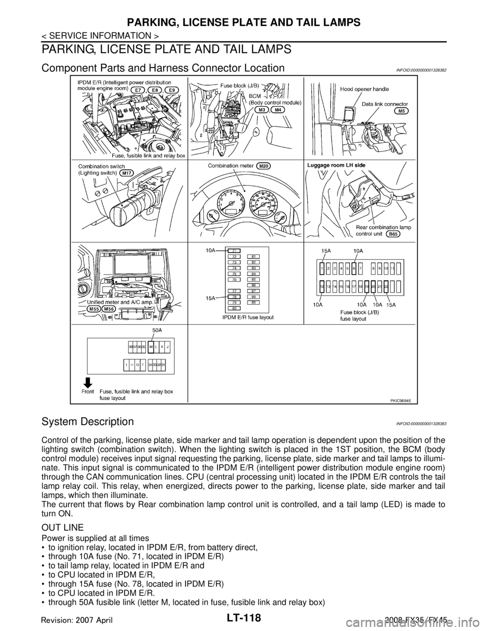
Component Parts and Harness Connector LocationINFOID:0000000001328382
System DescriptionINFOID:0000000001328383
Control of the parking, license plate, side marker and tail lamp operation is dependent upon the position of the
lighting switch (combination switch). When the lighting switch is placed in the 1ST position, the BCM (body
control module) receives input signal requesting the parki ng, license plate, side marker and tail lamps to illumi-
nate. This input signal is communicated to the IPDM E/R (intelligent power distribution module engine room)
through the CAN communication lines. CPU (central processi ng unit) located in the IPDM E/R controls the tail
lamp relay coil. This relay, when energized, directs pow er to the parking, license plate, side marker and tail
lamps, which then illuminate.
The current that flows by Rear combination lamp cont rol unit is controlled, and a tail lamp (LED) is made to
turn ON.
OUT LINE
Power is supplied at all times
to ignition relay, located in IP DM E/R, from battery direct,
through 10A fuse (No. 71, located in IPDM E/R)
to tail lamp relay, located in IPDM E/R and
to CPU located in IPDM E/R,
through 15A fuse (No. 78, located in IPDM E/R)
to CPU located in IPDM E/R.
through 50A fusible link (letter M, located in fuse, fusible link and relay box)
PKIC9694E
3AA93ABC3ACD3AC03ACA3AC03AC63AC53A913A773A893A873A873A8E3A773A983AC73AC93AC03AC3
3A893A873A873A8F3A773A9D3AAF3A8A3A8C3A863A9D3AAF3A8B3A8C
Page 3221 of 3924
![INFINITI FX35 2008 Service Manual
PARKING, LICENSE PLATE AND TAIL LAMPS
LT-119
< SERVICE INFORMATION >
C
D E
F
G H
I
J
L
M A
B
LT
N
O P
to BCM terminal 55,
through 15A fuse [No. 22, located in fuse block (J/B)]
to BCM terminal INFINITI FX35 2008 Service Manual
PARKING, LICENSE PLATE AND TAIL LAMPS
LT-119
< SERVICE INFORMATION >
C
D E
F
G H
I
J
L
M A
B
LT
N
O P
to BCM terminal 55,
through 15A fuse [No. 22, located in fuse block (J/B)]
to BCM terminal](/manual-img/42/57017/w960_57017-3220.png)
PARKING, LICENSE PLATE AND TAIL LAMPS
LT-119
< SERVICE INFORMATION >
C
D E
F
G H
I
J
L
M A
B
LT
N
O P
to BCM terminal 55,
through 15A fuse [No. 22, located in fuse block (J/B)]
to BCM terminal 42,
through 10A fuse [No. 20, located in fuse block (J/B)]
to rear combination lamp control unit terminal 1,
through 10A fuse [No. 19, located in fuse block (J/B)]
to combination meter terminal 8 and
to unified meter and A/C amp. terminal 21.
With the ignition switch in ON or START position, power is supplied
through ignition relay, located in IPDM E/R, from battery direct,
through 15A fuse [No. 1, located in fuse block (J/B)]
to BCM terminal 38,
through 10A fuse [No. 14, located in fuse block (J/B)]
to combination meter terminal 7 and
through 10A fuse [No. 12, located in fuse block (J/B)]
to unified meter and A/C amp. terminal 22.
With ignition switch in ACC or ON position, power is supplied
through 10A fuse [No. 6, located in fuse block (J/B)]
to BCM terminal 11.
Ground is supplied
to rear combination lamp control unit terminal 7 and
to IPDM E/R terminals 38 and 60
through grounds E21, E50 and E51,
to BCM terminals 49 and 52
to combination meter terminals 5, 6 and 15, and
to unified meter and A/C amp. terminals 29 and 30
through grounds M35, M45 and M85.
OPERATION BY LIGHTING SWITCH
With the lighting switch in the 1ST or 2ND position (or if the auto light system is activated), the BCM receives
input signal requesting the parking, license plate, side ma rker and tail lamps to illuminate. This input signal is
communicated to the IPDM E/R through the CAN communi cation. The CPU located in the IPDM E/R controls
the tail lamp relay coil, which when energized, directs power.
through IPDM E/R terminal 22
to front side marker lamp LH terminal 1
to parking lamp LH terminal 2
to license plate lamp LH terminal 1
to rear combination lamp LH terminal 1
to rear combination lamp control unit terminal 2
to front side marker lamp RH terminal 1
to parking lamp RH terminal 2
to license plate lamp RH terminal 1 and
to rear combination lamp RH terminal 1.
Ground is supplied at all times
to front side marker lamp LH terminal 2
through grounds E21, E50 and E51,
to parking lamp LH terminal 3
through grounds E21, E50 and E51,
to license plate lamp LH terminal 2
through grounds B15 and B45,
to rear combination lamp LH terminal 2
through grounds B15 and B45,
to front side marker lamp RH terminal 2
through grounds E21, E50 and E51,
to parking lamp RH terminal 3
through grounds E21, E50 and E51,
to license plate lamp RH terminal 2
through grounds B15 and B45,
to rear combination lamp RH terminal 2
through grounds B203 and B210,
to rear combination lamp control unit terminal 7
through grounds E21, E50 and E51.
3AA93ABC3ACD3AC03ACA3AC03AC63AC53A913A773A893A873A873A8E3A773A983AC73AC93AC03AC3
3A893A873A873A8F3A773A9D3AAF3A8A3A8C3A863A9D3AAF3A8B3A8C
Page 3222 of 3924

LT-120
< SERVICE INFORMATION >
PARKING, LICENSE PLATE AND TAIL LAMPS
With power and ground supplied, the parking, license plate, side marker and tail lamps illuminate.
COMBINATION SWITCH READING FUNCTION
Refer to BCS-4, "System Description".
EXTERIOR LAMP BATTERY SAVER CONTROL
When the combination switch (lighting switch) is in the 1ST (or 2ND) position, and the ignition switch is turned
from ON or ACC to OFF, the battery saver control feature is activated.
Under this condition, the parking, license, side marker and tail lamps remain illuminated for 5 minutes, then the
parking, license plate, side marker and tail lamps are turned off.
Exterior lamp battery saver control mode can be changed by the function setting of CONSULT-III.
CAN Communication System DescriptionINFOID:0000000001328384
CAN (Controller Area Network) is a serial communication line for real time application. It is an on-vehicle mul-
tiplex communication line with high data communication s peed and excellent error detection ability. Many elec-
tronic control units are equipped onto a vehicle, and each control unit shares information and links with other
control units during operation (not independent). In CA N communication, control units are connected with 2
communication lines (CAN H line, CAN L line) allowing a high rate of information transmission with less wiring.
Each control unit transmits/receives data but selectively reads required data only.
CAN Communication UnitINFOID:0000000001328385
Refer to LAN-43, "CAN System Specification Chart".
3AA93ABC3ACD3AC03ACA3AC03AC63AC53A913A773A893A873A873A8E3A773A983AC73AC93AC03AC3
3A893A873A873A8F3A773A9D3AAF3A8A3A8C3A863A9D3AAF3A8B3A8C
Page 3228 of 3924
LT-126
< SERVICE INFORMATION >
PARKING, LICENSE PLATE AND TAIL LAMPS
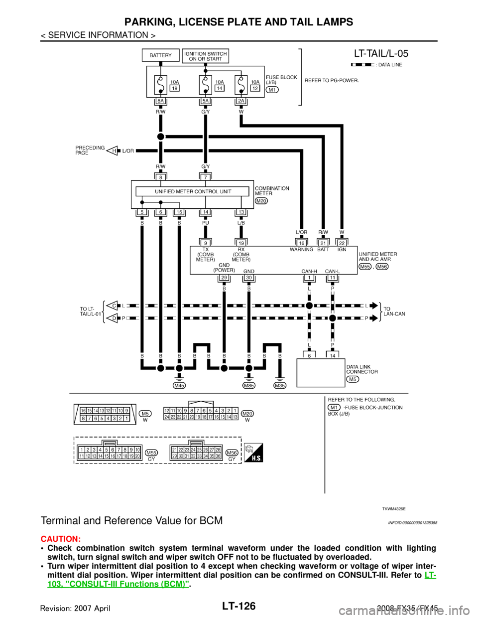
Terminal and Reference Value for BCM
INFOID:0000000001328388
CAUTION:
Check combination switch system terminal waveform under the loaded condition with lighting
switch, turn signal switch and wiper switch OFF not to be fluctuated by overloaded.
Turn wiper intermittent dial posi tion to 4 except when checking wavef orm or voltage of wiper inter-
mittent dial position. Wiper intermittent dial position can be confirmed on CONSULT-III. Refer to LT-
103, "CONSULT-III Functions (BCM)".
TKWM4326E
3AA93ABC3ACD3AC03ACA3AC03AC63AC53A913A773A893A873A873A8E3A773A983AC73AC93AC03AC3
3A893A873A873A8F3A773A9D3AAF3A8A3A8C3A863A9D3AAF3A8B3A8C
Page 3229 of 3924

PARKING, LICENSE PLATE AND TAIL LAMPS
LT-127
< SERVICE INFORMATION >
C
D E
F
G H
I
J
L
M A
B
LT
N
O P
Terminal and Reference Value for IPDM E/RINFOID:0000000001328389
Te r m i n a l No. Wire
color Signal name Measuring condition
Reference value
Ignition
switch Operation or condition
2GY Combination
switch input 5
ONLighting, turn, wip-
er switch
(Wiper intermittent
dial position 4) OFF Approx. 0 V
Lighting switch 1ST
Approx. 1.0 V
11 L G Ignition switch
(ACC)
ACC — Battery voltage
33 G Combination
switch output 4 ONLighting, turn, wip-
er switch
(Wiper intermittent
dial position 4) OFF
Approx. 7.2 V
Lighting switch 1ST
(The same result with
lighting switch 2ND) Approx. 1.2 V
38 W/L Ignition switch
(ON)
ON — Battery voltage
39 L CAN − H— — —
40 P CAN − L— — —
42 L/R Battery power
supply OFF — Battery voltage
49 B Ground ON — Approx. 0 V
52 B Ground ON — Approx. 0 V
55 G Battery power
supply OFF — Battery voltage
PKIB4959J
PKIB4960J
PKIB4958J
Te r m i n a l
No. Wire
color Signal name Measuring condition
Reference value
Ignition
switch Operation or condition
22 R Parking, license plate,
side marker, and tail
lamps ON
Lighting switch
1ST position OFF Approx. 0 V
ON Battery voltage
38 B Ground ON — Approx. 0 V
48 L CAN − H— — —
3AA93ABC3ACD3AC03ACA3AC03AC63AC53A913A773A893A873A873A8E3A773A983AC73AC93AC03AC3
3A893A873A873A8F3A773A9D3AAF3A8A3A8C3A863A9D3AAF3A8B3A8C
Page 3231 of 3924
PARKING, LICENSE PLATE AND TAIL LAMPS
LT-129
< SERVICE INFORMATION >
C
D E
F
G H
I
J
L
M A
B
LT
N
O P
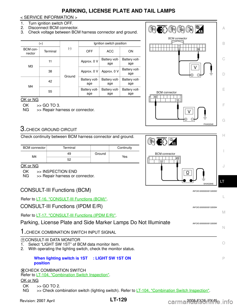
1. Turn ignition switch OFF.
2. Disconnect BCM connector.
3. Check voltage between BCM harness connector and ground.
OK or NG
OK >> GO TO 3.
NG >> Repair harness or connector.
3.CHECK GROUND CIRCUIT
Check continuity between BCM harness connector and ground.
OK or NG
OK >> INSPECTION END
NG >> Repair harness or connector.
CONSULT-III Functions (BCM)INFOID:0000000001328393
Refer to LT-16, "CONSULT-III Functions (BCM)".
CONSULT-III Functions (IPDM E/R)INFOID:0000000001328394
Refer to LT-17, "CONSULT-III Functions (IPDM E/R)".
Parking, License Plate and Side Marker Lamps Do Not IlluminateINFOID:0000000001328395
1.CHECK COMBINATION SWITCH INPUT SIGNAL
CONSULT-III DATA MONITOR
1. Select “LIGHT SW 1ST” of BCM data monitor item.
2. With operating the lighting switch, check the monitor status.
CHECK COMBINATION SWITCH
Refer to LT-104, "
Combination Switch Inspection".
OK or NG
OK >> GO TO 2.
NG >> Check combination switch (lighting switch). Refer to LT-104, "
Combination Switch Inspection".
(+)
(-)Ignition switch position
BCM con- nector Te r m i n a l O F F A C C O N
M3 11
Ground Approx. 0 V
Battery volt-
age Battery volt-
age
38 Approx. 0 V Approx. 0 V Battery volt-
age
M4 42
Battery volt-
age Battery volt-
age Battery volt-
age
55 Battery volt-
age Battery volt-
age Battery volt-
age
PKIA5204E
BCM connector Terminal Continuity
M4 49 Ground
Ye s
52
SKIA5294E
When lighting switch is 1ST
position : LIGHT SW 1ST ON
3AA93ABC3ACD3AC03ACA3AC03AC63AC53A913A773A893A873A873A8E3A773A983AC73AC93AC03AC3
3A893A873A873A8F3A773A9D3AAF3A8A3A8C3A863A9D3AAF3A8B3A8C