2008 INFINITI FX35 weight
[x] Cancel search: weightPage 2726 of 3924
![INFINITI FX35 2008 Service Manual
EM-242
< SERVICE INFORMATION >[VK45DE]
CYLINDER BLOCK
Refer to
GI-8, "Component" for symbols in the figure.
Disassembly and AssemblyINFOID:0000000001325804
DISASSEMBLY
NOTE:
Explained here is how INFINITI FX35 2008 Service Manual
EM-242
< SERVICE INFORMATION >[VK45DE]
CYLINDER BLOCK
Refer to
GI-8, "Component" for symbols in the figure.
Disassembly and AssemblyINFOID:0000000001325804
DISASSEMBLY
NOTE:
Explained here is how](/manual-img/42/57017/w960_57017-2725.png)
EM-242
< SERVICE INFORMATION >[VK45DE]
CYLINDER BLOCK
Refer to
GI-8, "Component" for symbols in the figure.
Disassembly and AssemblyINFOID:0000000001325804
DISASSEMBLY
NOTE:
Explained here is how to disassemble with engine stand supporting transmission surface. When using differ-
ent type of engine stand, note with difference in steps and etc.
1. Remove engine assembly from vehicle, and separa te front suspension member, transmission and front
final drive from engine. Refer to EM-237, "
Component".
2. Remove the parts that may restrict installation of engine to widely use engine stand. NOTE:
The procedure is described assuming that you use wi dely use engine holding the surface, to which trans-
mission is installed.
a. Remove drive plate. Holding ring gear with ring gear stopper (SST).
Loosen mounting bolts diagonally order.
CAUTION:
Do not disassemble drive plate.
Do not place drive plate with signal plate facing down.
When handling signal plate, take care not to damage or scratch it.
Handle signal plate in a manner that prevents it from becoming magnetized.
b. Remove engine rear plate.
3. Lift engine with hoist to install it onto widely use engine stand. CAUTION:
Use engine stand that has a load capacity [approximately 240 kg ( 529 lb) or more] large enough for
supporting the engine weight.
If the load capacity of stand is not adequate, remo ve the following parts beforehand to reduce the poten-
tial risk of overturning stand.
- Intake manifolds (upper and lower): Refer to EM-175, "
Component".
- Exhaust manifold: Refer to EM-179, "
Component".
- Fuel tube and fuel injector assembly: Refer to EM-190, "
Component".
22. Main bearing 23. Rear plate 24. Crankshaft
25. Pilot converter 26. Drive plate 27. Thrust bearing
28. Side bolt 29. Reinforcement plate 30. Crankshaft position sensor (POS)
31. O-ring 32. Rear oil seal 33. Rear oil seal retainer
A.Refererence: Installed on transmis-
sion B. Refer to
EM-242
C. Right bank
D. Cylinder block heater (For Canada) E. Chamfered F. Crankshaft side : Engine front
PBIC1656E
PBIC2367E
3AA93ABC3ACD3AC03ACA3AC03AC63AC53A913A773A893A873A873A8E3A773A983AC73AC93AC03AC3
3A893A873A873A8F3A773A9D3AAF3A8A3A8C3A863A9D3AAF3A8B3A8C
Page 2728 of 3924
![INFINITI FX35 2008 Service Manual
EM-244
< SERVICE INFORMATION >[VK45DE]
CYLINDER BLOCK
10. Remove piston rings from piston.
Before removing the piston rings, check the piston ring side clearance. Refer to EM-256, "
Inspection
Af INFINITI FX35 2008 Service Manual
EM-244
< SERVICE INFORMATION >[VK45DE]
CYLINDER BLOCK
10. Remove piston rings from piston.
Before removing the piston rings, check the piston ring side clearance. Refer to EM-256, "
Inspection
Af](/manual-img/42/57017/w960_57017-2727.png)
EM-244
< SERVICE INFORMATION >[VK45DE]
CYLINDER BLOCK
10. Remove piston rings from piston.
Before removing the piston rings, check the piston ring side clearance. Refer to EM-256, "
Inspection
After Disassembly".
Use piston ring expander (commercial service tool).
CAUTION:
When removing piston rings, be careful not to damage piston.
Be careful not to damage piston rings by expanding them
excessively.
11. Remove piston from connecting rod as follows:
a. Using snap ring pliers, remove the snap rings.
b. Heat piston to 60 to 70 °C (140 to 158 °F) with industrial use drier
or equivalent.
c. Push out piston pin with stick of outer diameter approximately 20 mm (0.8 in).
12. Remove rear oil seal retainer from cylinder block. Insert screwdriver or similar tool between rear end of crankshaft counter weight and rear oil sealretainer, and separate liquid gasket to remove.
CAUTION:
Be careful not to damage the mating surfaces.
13. Using screwdriver or similar tool, and lever off rear oil seal from rear oil seal retainer.
14. Remove main bearing cap as follows:
PBIC0087E
PBIC0088E
PBIC0089E
EMM0072D
3AA93ABC3ACD3AC03ACA3AC03AC63AC53A913A773A893A873A873A8E3A773A983AC73AC93AC03AC3
3A893A873A873A8F3A773A9D3AAF3A8A3A8C3A863A9D3AAF3A8B3A8C
Page 2865 of 3924
PRECAUTIONSGI-3
< SERVICE INFORMATION >
C
DE
F
G H
I
J
K L
M B
GI
N
O P
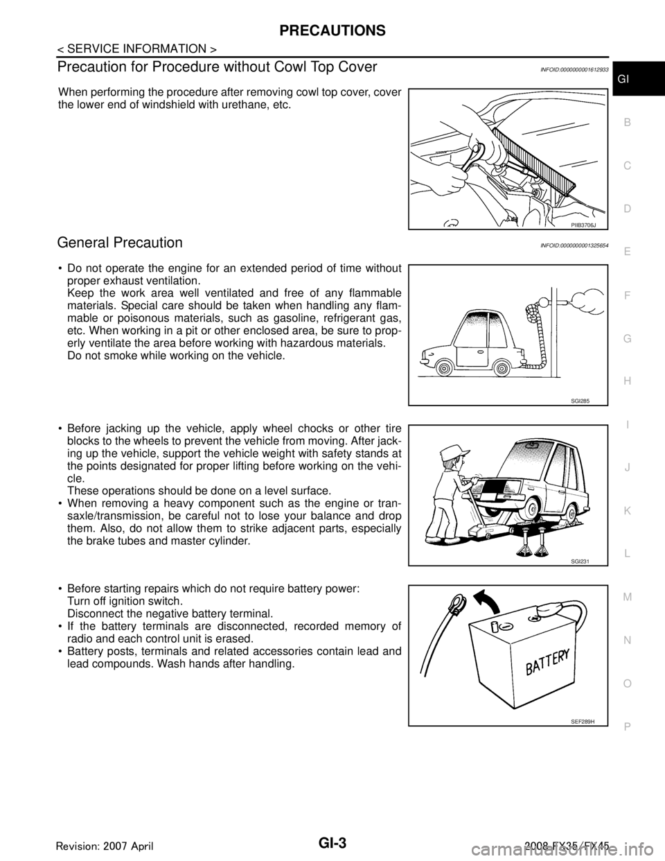
Precaution for Procedur e without Cowl Top CoverINFOID:0000000001612933
When performing the procedure after removing cowl top cover, cover
the lower end of windshield with urethane, etc.
General PrecautionINFOID:0000000001325654
Do not operate the engine for an extended period of time without
proper exhaust ventilation.
Keep the work area well ventilated and free of any flammable
materials. Special care should be taken when handling any flam-
mable or poisonous materials, such as gasoline, refrigerant gas,
etc. When working in a pit or ot her enclosed area, be sure to prop-
erly ventilate the area before working with hazardous materials.
Do not smoke while working on the vehicle.
Before jacking up the vehicle, apply wheel chocks or other tire
blocks to the wheels to prevent the vehicle from moving. After jack-
ing up the vehicle, support the vehicle weight with safety stands at
the points designated for proper lifting before working on the vehi-
cle.
These operations should be done on a level surface.
When removing a heavy component such as the engine or tran- saxle/transmission, be careful not to lose your balance and drop
them. Also, do not allow them to strike adjacent parts, especially
the brake tubes and master cylinder.
Before starting repairs which do not require battery power: Turn off ignition switch.
Disconnect the negative battery terminal.
If the battery terminals are disconnected, recorded memory of radio and each control unit is erased.
Battery posts, terminals and related accessories contain lead and
lead compounds. Wash hands after handling.
PIIB3706J
SGI285
SGI231
SEF289H
3AA93ABC3ACD3AC03ACA3AC03AC63AC53A913A773A893A873A873A8E3A773A983AC73AC93AC03AC3
3A893A873A873A8F3A773A9D3AAF3A8A3A8C3A863A9D3AAF3A8B3A8C
Page 2880 of 3924
GI-18
< SERVICE INFORMATION >
HOW TO USE THIS MANUAL
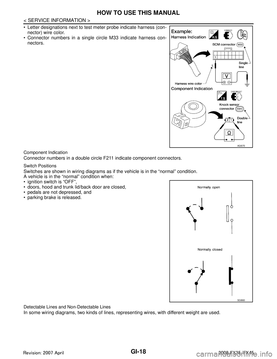
Letter designations next to test meter probe indicate harness (con-nector) wire color.
Connector numbers in a single circle M33 indicate harness con-
nectors.
Component Indication
Connector numbers in a double circle F211 indicate component connectors.
Switch Positions
Switches are shown in wiring diagrams as if the vehicle is in the “normal” condition.
A vehicle is in the “normal” condition when:
ignition switch is “OFF”,
doors, hood and trunk lid/back door are closed,
pedals are not depressed, and
parking brake is released.
Detectable Lines and Non-Detectable Lines
In some wiring diagrams, two kinds of lines, r epresenting wires, with different weight are used.
AGI070
SGI860
3AA93ABC3ACD3AC03ACA3AC03AC63AC53A913A773A893A873A873A8E3A773A983AC73AC93AC03AC3
3A893A873A873A8F3A773A9D3AAF3A8A3A8C3A863A9D3AAF3A8B3A8C
Page 2881 of 3924
HOW TO USE THIS MANUALGI-19
< SERVICE INFORMATION >
C
DE
F
G H
I
J
K L
M B
GI
N
O P
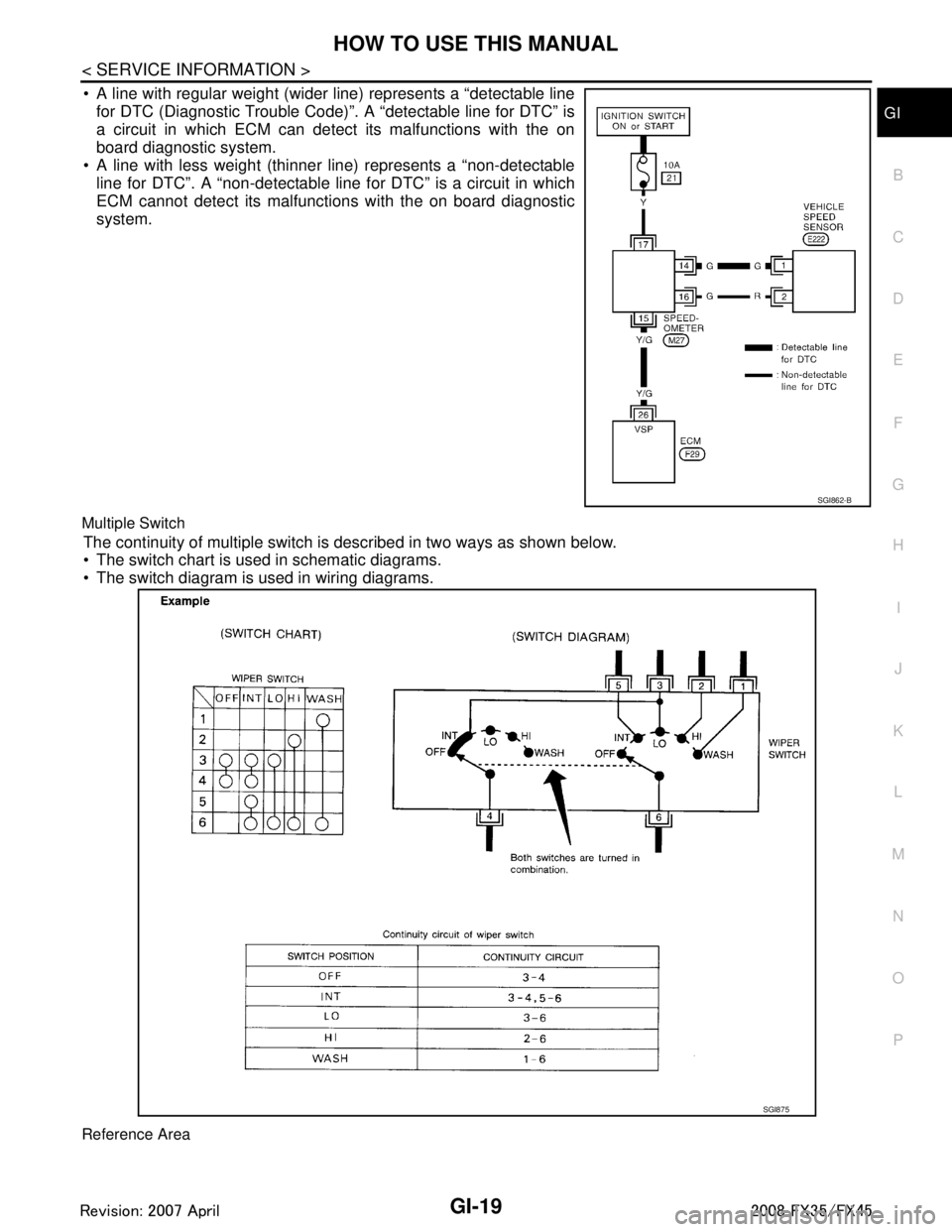
A line with regular weight (wider line) represents a “detectable line for DTC (Diagnostic Trouble Code)”. A “detectable line for DTC” is
a circuit in which ECM can detect its malfunctions with the on
board diagnostic system.
A line with less weight (thinner line) represents a “non-detectable line for DTC”. A “non-detectable line for DTC” is a circuit in which
ECM cannot detect its malfunctions with the on board diagnostic
system.
Multiple Switch
The continuity of multiple switch is described in two ways as shown below.
The switch chart is used in schematic diagrams.
The switch diagram is used in wiring diagrams.
Reference Area
SGI862-B
SGI875
3AA93ABC3ACD3AC03ACA3AC03AC63AC53A913A773A893A873A873A8E3A773A983AC73AC93AC03AC3
3A893A873A873A8F3A773A9D3AAF3A8A3A8C3A863A9D3AAF3A8B3A8C
Page 3129 of 3924
HEADLAMP - XENON TYPE -LT-27
< SERVICE INFORMATION >
C
DE
F
G H
I
J
L
M A
B
LT
N
O P
Xenon Headlamp Trouble DiagnosisINFOID:0000000001328286
1.CHECK 1: XENON HEADLAMP LIGHTING
Install normal xenon bulb to corresponding xenon bulb headlamp, and check if lamp lights up.
OK or NG
OK >> Replace xenon bulb.
NG >> GO TO 2.
2.CHECK 2: XENON HEADLAMP LIGHTING
Install normal HID control unit to corresponding xenon headlamp, and check if lamp lights up.
OK or NG
OK >> Replace HID control unit.
NG >> GO TO 3.
3.CHECK 3: XENON HEADLAMP LIGHTING
Install normal xenon lamp housing assembly to corresponding xenon headlamp, and check if lamp lights up.
OK or NG
OK >> Replace xenon headlamp housing assembly. [Malfunction in starter (boosting circuit) in xenon headlamp housing]
NG >> INSPECTION END
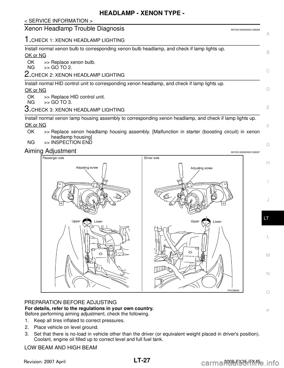
Aiming AdjustmentINFOID:0000000001328287
PREPARATION BEFORE ADJUSTING
For details, refer to the regulations in your own country.
Before performing aiming adjustment, check the following.
1. Keep all tires inflated to correct pressures.
2. Place vehicle on level ground.
3. Set that there is no-load in vehicle other than the driv er (or equivalent weight placed in driver's position).
Coolant, engine oil filled up to correct level and full fuel tank.
LOW BEAM AND HIGH BEAM
PKIC9684E
3AA93ABC3ACD3AC03ACA3AC03AC63AC53A913A773A893A873A873A8E3A773A983AC73AC93AC03AC3
3A893A873A873A8F3A773A9D3AAF3A8A3A8C3A863A9D3AAF3A8B3A8C
Page 3177 of 3924
FRONT FOG LAMPLT-75
< SERVICE INFORMATION >
C
DE
F
G H
I
J
L
M A
B
LT
N
O P
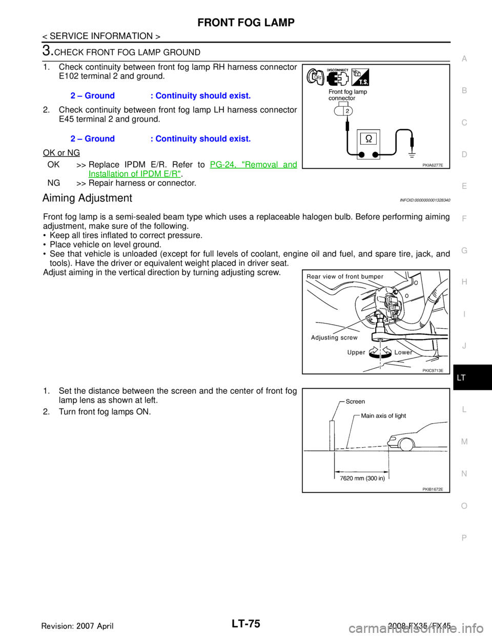
3.CHECK FRONT FOG LAMP GROUND
1. Check continuity between front fog lamp RH harness connector E102 terminal 2 and ground.
2. Check continuity between front fog lamp LH harness connector E45 terminal 2 and ground.
OK or NG
OK >> Replace IPDM E/R. Refer to PG-24, "Removal and
Installation of IPDM E/R".
NG >> Repair harness or connector.
Aiming AdjustmentINFOID:0000000001328340
Front fog lamp is a semi-sealed beam type which uses a replaceable halogen bulb. Before performing aiming
adjustment, make sure of the following.
Keep all tires inflated to correct pressure.
Place vehicle on level ground.
See that vehicle is unloaded (except for full levels of coolant, engine oil and fuel, and spare tire, jack, and tools). Have the driver or equivalent weight placed in driver seat.
Adjust aiming in the vertical direction by turning adjusting screw.
1. Set the distance between the scr een and the center of front fog
lamp lens as shown at left.
2. Turn front fog lamps ON. 2 – Ground : Continuity should exist.
2 – Ground : Continuity should exist.
PKIA6277E
PKIC9713E
PKIB1672E
3AA93ABC3ACD3AC03ACA3AC03AC63AC53A913A773A893A873A873A8E3A773A983AC73AC93AC03AC3
3A893A873A873A8F3A773A9D3AAF3A8A3A8C3A863A9D3AAF3A8B3A8C
Page 3301 of 3924
![INFINITI FX35 2008 Service Manual
LU-16
< SERVICE INFORMATION >[VQ35DE]
OIL PUMP
Measure the clearance with feeler gauge.
- Clearance between oil pump outer rotor and oil pump body (posi-
tion “1”)
- Tip clearance between oil p INFINITI FX35 2008 Service Manual
LU-16
< SERVICE INFORMATION >[VQ35DE]
OIL PUMP
Measure the clearance with feeler gauge.
- Clearance between oil pump outer rotor and oil pump body (posi-
tion “1”)
- Tip clearance between oil p](/manual-img/42/57017/w960_57017-3300.png)
LU-16
< SERVICE INFORMATION >[VQ35DE]
OIL PUMP
Measure the clearance with feeler gauge.
- Clearance between oil pump outer rotor and oil pump body (posi-
tion “1”)
- Tip clearance between oil pump inner rotor and oil pump outer rotor (position “2”)
Measure the clearance with feeler gauge and straightedge.
- Side clearance between oil pump inner rotor and oil pump body
(position “3”)
- Side clearance between oil pump outer rotor and oil pump body (position “4”)
Calculate the clearance between oil pump inner rotor and oil pump body as follows:
OIL PUMP BODY INNER DIAMETER
- Measure the inner diameter of oil pump body with inside microme-
ter. (Position “5”)
OIL PUMP INNER ROTOR OUTER DIAMETER
- Measure the outer diameter of protruded portion of oil pump inner rotor with micrometer. (Position “6”)
OIL PUMP INNER ROTOR TO OIL PUMP BODY CLEARANCE- (Clearance) = (Oil pump body inner diamete r) – (Oil pump inner rotor outer diameter)
If measured/calculated values are out of the standard, replace oil pump assembly.
Regulator Valve Clearance
(Clearance) = (Valve hole diameter) – (Regulator valve outer diame-
ter)
If the calculated value is out of the standard, replace oil pump
assembly.
CAUTION:
Coat regulator valve with engine oil.
Make sure that it falls smooth ly into valve hole by its own
weight.
ASSEMBLY
Standard : 0.114 - 0.260 mm (0.004 - 0.010 in)
Standard : Below 0.180 mm (0.007 in)
SLC932A
Standard : 0.030 - 0.070 mm (0.001 - 0.003 in)
Standard : 0.050 - 0.110 mm (0.002 - 0.004 in)
SLC933A
PBIC0821E
Standard : 0.045 - 0.091 mm (0.0018 - 0.0036 in)
Standard : 0.040 - 0.097 mm (0.0016 - 0.0038 in)
PBIC0822E
3AA93ABC3ACD3AC03ACA3AC03AC63AC53A913A773A893A873A873A8E3A773A983AC73AC93AC03AC3
3A893A873A873A8F3A773A9D3AAF3A8A3A8C3A863A9D3AAF3A8B3A8C