2008 INFINITI FX35 engine stall
[x] Cancel search: engine stallPage 3515 of 3924
SERVICE DATA AND SPECIFICATIONS (SDS)
RAX-17
< SERVICE INFORMATION >
C EF
G H
I
J
K L
M A
B
RAX
N
O P
SERVICE DATA AND SPECIFICATIONS (SDS)
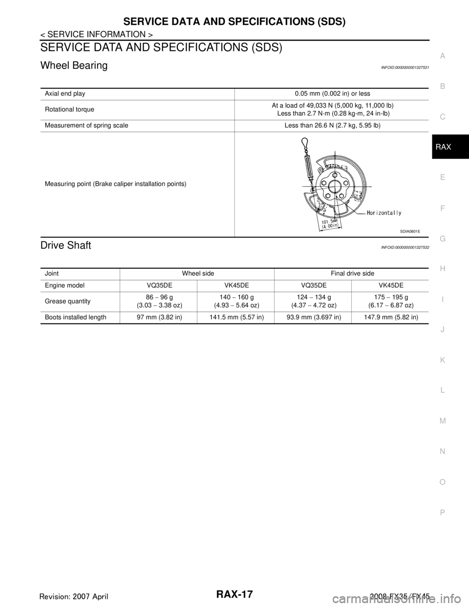
Wheel BearingINFOID:0000000001327531
Drive ShaftINFOID:0000000001327532
Axial end play 0.05 mm (0.002 in) or less
Rotational torque At a load of 49,033 N (5,000 kg, 11,000 lb)
Less than 2.7 N·m (0.28 kg-m, 24 in-lb)
Measurement of spring scale Less than 26.6 N (2.7 kg, 5.95 lb)
Measuring point (Brake caliper installation points)
SDIA0801E
Joint Wheel side Final drive side
Engine model VQ35DE VK45DE VQ35DE VK45DE
Grease quantity 86
− 96 g
(3.03 − 3.38 oz) 140
− 160 g
(4.93 − 5.64 oz) 124
− 134 g
(4.37 − 4.72 oz) 175
− 195 g
(6.17 − 6.87 oz)
Boots installed length 97 mm (3.82 in) 141.5 mm (5.57 in) 93.9 mm (3.697 in) 147.9 mm (5.82 in)
3AA93ABC3ACD3AC03ACA3AC03AC63AC53A913A773A893A873A873A8E3A773A983AC73AC93AC03AC3
3A893A873A873A8F3A773A9D3AAF3A8A3A8C3A863A9D3AAF3A8B3A8C
Page 3551 of 3924
DIFFERENTIAL GEAR OILRFD-9
< SERVICE INFORMATION >
CEF
G H
I
J
K L
M A
B
RFD
N
O P
DIFFERENTIAL GEAR OIL
Changing Differential Gear OilINFOID:0000000001327495
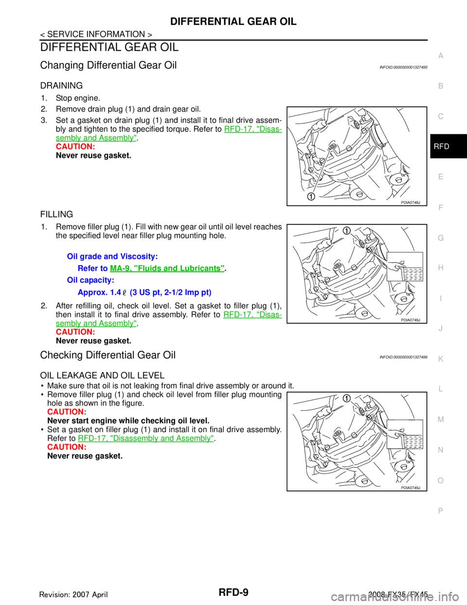
DRAINING
1. Stop engine.
2. Remove drain plug (1) and drain gear oil.
3. Set a gasket on drain plug (1) and install it to final drive assem- bly and tighten to the specified torque. Refer to RFD-17, "
Disas-
sembly and Assembly".
CAUTION:
Never reuse gasket.
FILLING
1. Remove filler plug (1). Fill with new gear oil until oil level reaches the specified level near filler plug mounting hole.
2. After refilling oil, check oil level. Set a gasket to filler plug (1), then install it to final drive assembly. Refer to RFD-17, "
Disas-
sembly and Assembly".
CAUTION:
Never reuse gasket.
Checking Differential Gear OilINFOID:0000000001327496
OIL LEAKAGE AND OIL LEVEL
Make sure that oil is not leaking from final drive assembly or around it.
Remove filler plug (1) and check oil level from filler plug mounting hole as shown in the figure.
CAUTION:
Never start engine while checking oil level.
Set a gasket on filler plug (1) and install it on final drive assembly.
Refer to RFD-17, "
Disassembly and Assembly".
CAUTION:
Never reuse gasket.
PDIA0748J
Oil grade and Viscosity:
Refer to MA-9, "
Fluids and Lubricants".
Oil capacity:
Approx. 1.4 (3 US pt, 2-1/2 Imp pt)
PDIA0749J
PDIA0749J
3AA93ABC3ACD3AC03ACA3AC03AC63AC53A913A773A893A873A873A8E3A773A983AC73AC93AC03AC3
3A893A873A873A8F3A773A9D3AAF3A8A3A8C3A863A9D3AAF3A8B3A8C
Page 3583 of 3924
RSU-2
< SERVICE INFORMATION >
PRECAUTIONS
SERVICE INFORMATION
PRECAUTIONS
CautionsINFOID:0000000001327548
• When installing rubber bushings, final tightening must be carried out under unladen conditions with tires on
level ground. Oil will shorten the life of rubber bushings. Be sure to wipe off any spilled oil.
Unladen conditions means that fuel, engine coolant and lubricant are full. Spare tire, jack, hand tools and
mats are in designated positions.
After servicing suspension parts, be sure to check wheel alignment.
Caulking nuts are not reusable. Always use new ones w hen installing. Since new caulking nuts are pre-oiled,
tighten as they are.
3AA93ABC3ACD3AC03ACA3AC03AC63AC53A913A773A893A873A873A8E3A773A983AC73AC93AC03AC3
3A893A873A873A8F3A773A9D3AAF3A8A3A8C3A863A9D3AAF3A8B3A8C
Page 3586 of 3924
REAR SUSPENSION ASSEMBLYRSU-5
< SERVICE INFORMATION >
C
DF
G H
I
J
K L
M A
B
RSU
N
O P
REAR SUSPENSION ASSEMBLY
On-Vehicle Inspection and ServiceINFOID:0000000001327552
Make sure the mounting conditions (looseness, ba ck lash) of each component and component status (wear,
damage) are normal.
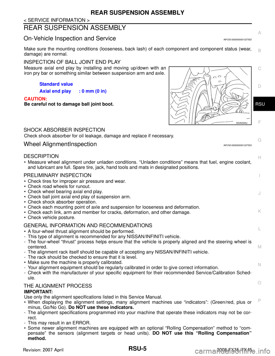
INSPECTION OF BALL JOINT END PLAY
Measure axial end play by installing and moving up/down with an
iron pry bar or something similar between suspension arm and axle.
CAUTION:
Be careful not to damage ball joint boot.
SHOCK ABSORBER INSPECTION
Check shock absorber for oil leakage, damage and replace if necessary.
Wheel AlignmentInspectionINFOID:0000000001327553
DESCRIPTION
Measure wheel alignment under unladen conditions. “U nladen conditions” means that fuel, engine coolant,
and lubricant are full. Spare tire, jack, hand tools and mats in designated positions.
PRELIMINARY INSPECTION
Check tires for improper air pressure and wear.
Check road wheels for runout.
Check wheel bearing axial end play.
Check ball joint axial end play of suspension arm.
Check shock absorber operation.
Check each mounting point of axle and suspension for looseness and deformation.
Check each link, arm and member for cracks, deformation, and other damage.
Check vehicle posture.
GENERAL INFORMATION AND RECOMMENDATIONS
A four-wheel thrust alignment should be performed.
- This type of alignment is recomm ended for any NISSAN/INFINITI vehicle.
- The four-wheel “thrust” process helps ensure that t he vehicle is properly aligned and the steering wheel is
centered.
- The alignment rack itself should be capable of accepting any NISSAN/INFINITI vehicle.
- The rack should be checked to ensure that it is level.
Make sure the machine is properly calibrated.
- Your alignment equipment should be regularly ca librated in order to give correct information.
- Check with the manufacturer of your specific equi pment for their recommended Service/Calibration Sched-
ule.
THE ALIGNMENT PROCESS
IMPORTANT:
Use only the alignment specificati ons listed in this Service Manual.
When displaying the alignment settings, many alignment machines use “indicators”: (Green/red, plus or
minus, Go/No Go). Do NOT use these indicators.
- The alignment specifications programmed into your machine that operate these indicators may not be cor-
rect.
- This may result in an ERROR.
Some newer alignment machines are equipped with an optional “Rolling Compensation” method to “com-
pensate” the sensors (alignment targets or head units). DO NOT use this “Rolling Compensation”
method. Standard value
Axial end play : 0 mm (0 in)
SEIA0245J
3AA93ABC3ACD3AC03ACA3AC03AC63AC53A913A773A893A873A873A8E3A773A983AC73AC93AC03AC3
3A893A873A873A8F3A773A9D3AAF3A8A3A8C3A863A9D3AAF3A8B3A8C
Page 3610 of 3924
SC-1
ELECTRICAL
C
DE
F
G H
I
J
L
M
SECTION SC
A
B
SC
N
O P
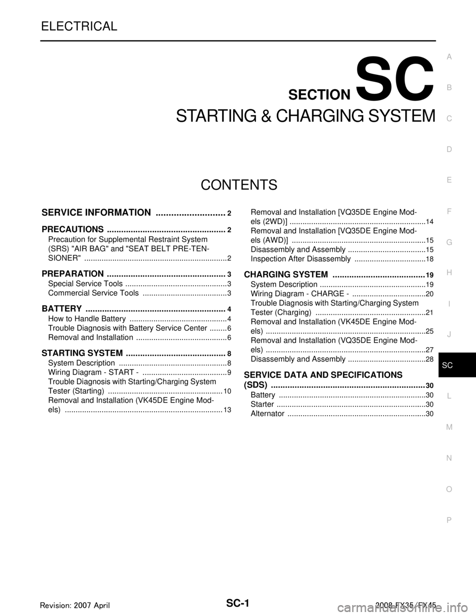
CONTENTS
STARTING & CHARGING SYSTEM
SERVICE INFORMATION .. ..........................2
PRECAUTIONS .............................................. .....2
Precaution for Supplemental Restraint System
(SRS) "AIR BAG" and "SEAT BELT PRE-TEN-
SIONER" ............................................................. ......
2
PREPARATION ...................................................3
Special Service Tools .......................................... ......3
Commercial Service Tools ........................................3
BATTERY ............................................................4
How to Handle Battery ........................................ ......4
Trouble Diagnosis with Battery Service Center .........6
Removal and Installation ...........................................6
STARTING SYSTEM ...........................................8
System Description ............................................. ......8
Wiring Diagram - START - ........................................9
Trouble Diagnosis with Starting/Charging System
Tester (Starting) ......................................................
10
Removal and Installation (VK45DE Engine Mod-
els) ..........................................................................
13
Removal and Installation [VQ35DE Engine Mod-
els (2WD)] ............................................................ ....
14
Removal and Installation [VQ35DE Engine Mod-
els (AWD)] ...............................................................
15
Disassembly and Assembly .....................................15
Inspection After Disassembly ..................................18
CHARGING SYSTEM .......................................19
System Description ..................................................19
Wiring Diagram - CHARGE - ...................................20
Trouble Diagnosis with Starting/Charging System
Tester (Charging) ....................................................
21
Removal and Installation (VK45DE Engine Mod-
els) ...........................................................................
25
Removal and Installation (VQ35DE Engine Mod-
els) ...........................................................................
27
Disassembly and Assembly .....................................28
SERVICE DATA AND SPECIFICATIONS
(SDS) .................................................................
30
Battery .....................................................................30
Starter ......................................................................30
Alternator .................................................................30
3AA93ABC3ACD3AC03ACA3AC03AC63AC53A913A773A893A873A873A8E3A773A983AC73AC93AC03AC3
3A893A873A873A8F3A773A9D3AAF3A8A3A8C3A863A9D3AAF3A8B3A8C
Page 3622 of 3924
STARTING SYSTEMSC-13
< SERVICE INFORMATION >
C
DE
F
G H
I
J
L
M A
B
SC
N
O P
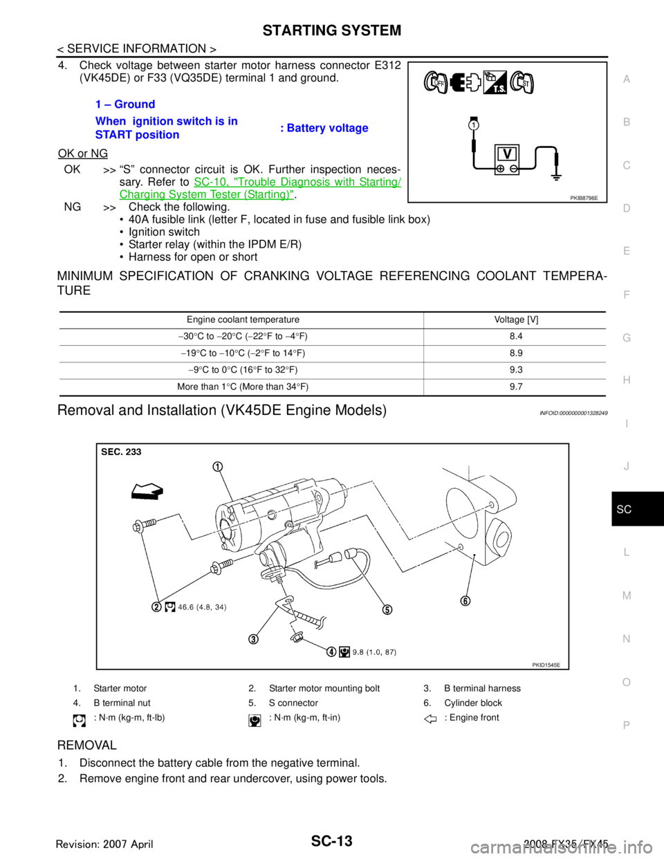
4. Check voltage between starter motor harness connector E312 (VK45DE) or F33 (VQ35DE) terminal 1 and ground.
OK or NG
OK >> “S” connector circuit is OK. Further inspection neces- sary. Refer to SC-10, "
Trouble Diagnosis with Starting/
Charging System Tester (Starting)".
NG >> Check the following.
40A fusible link (letter F, located in fuse and fusible link box)
Ignition switch
Starter relay (within the IPDM E/R)
Harness for open or short
MINIMUM SPECIFICATION OF CRANKING VO LTAGE REFERENCING COOLANT TEMPERA-
TURE
Removal and Installation (VK45DE Engine Models)INFOID:0000000001328249
REMOVAL
1. Disconnect the battery cable from the negative terminal.
2. Remove engine front and rear undercover, using power tools. 1 – Ground
When ignition switch is in
START position
: Battery voltage
PKIB8796E
Engine coolant temperature Voltage [V]
− 30 °C to −20 °C ( −22 °F to −4 °F) 8.4
− 19 °C to −10 °C ( −2 °F to 14 °F) 8.9
− 9 °C to 0 °C (16 °F to 32 °F) 9.3
More than 1 °C (More than 34 °F) 9.7
1. Starter motor 2. Starter motor mounting bolt 3. B terminal harness
4. B terminal nut 5. S connector 6. Cylinder block
: N·m (kg-m, ft-lb) : N·m (k g-m, ft-in) : Engine front
PKID1545E
3AA93ABC3ACD3AC03ACA3AC03AC63AC53A913A773A893A873A873A8E3A773A983AC73AC93AC03AC3
3A893A873A873A8F3A773A9D3AAF3A8A3A8C3A863A9D3AAF3A8B3A8C
Page 3623 of 3924
SC-14
< SERVICE INFORMATION >
STARTING SYSTEM
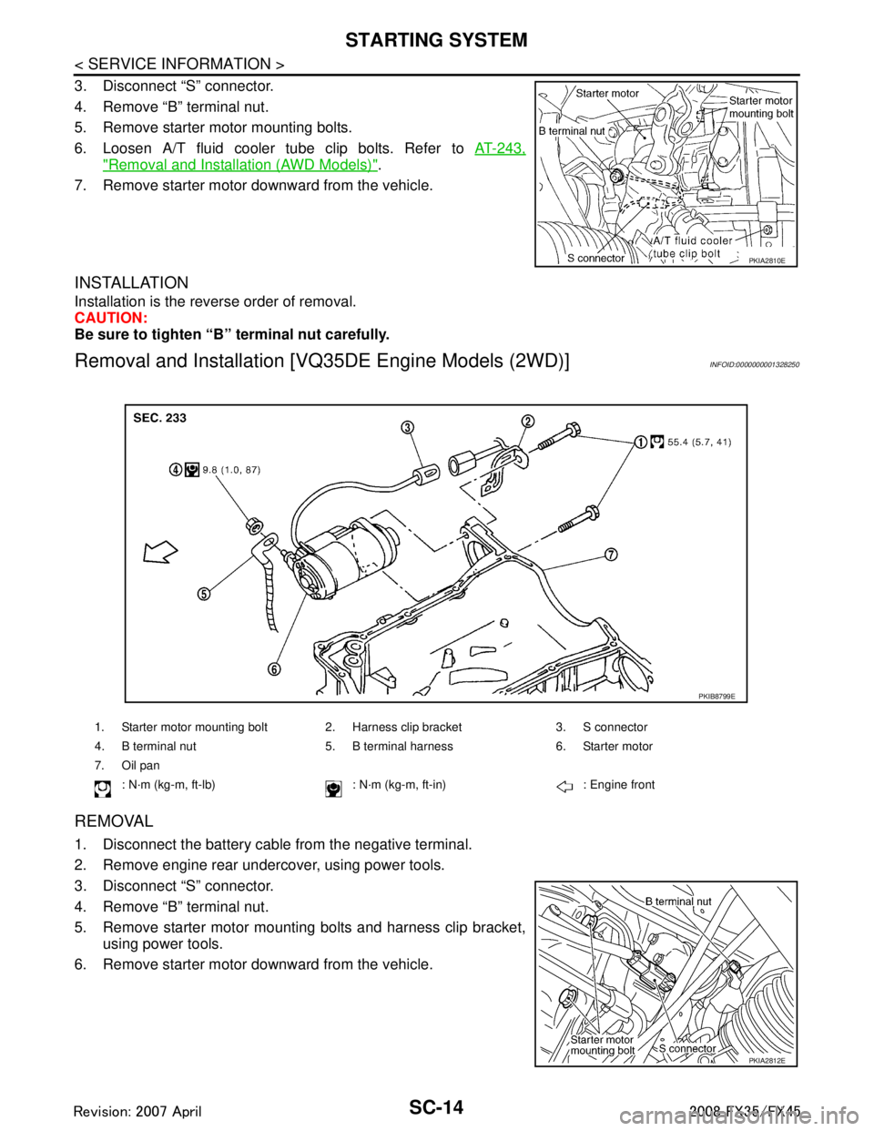
3. Disconnect “S” connector.
4. Remove “B” terminal nut.
5. Remove starter motor mounting bolts.
6. Loosen A/T fluid cooler tube clip bolts. Refer to AT-243,
"Removal and Installation (AWD Models)".
7. Remove starter motor downward from the vehicle.
INSTALLATION
Installation is the reverse order of removal.
CAUTION:
Be sure to tighten “B” terminal nut carefully.
Removal and Installation [V Q35DE Engine Models (2WD)]INFOID:0000000001328250
REMOVAL
1. Disconnect the battery cable from the negative terminal.
2. Remove engine rear undercover, using power tools.
3. Disconnect “S” connector.
4. Remove “B” terminal nut.
5. Remove starter motor mounting bolts and harness clip bracket,
using power tools.
6. Remove starter motor downward from the vehicle.
PKIA2810E
1. Starter motor mounting bolt 2. Harness clip bracket 3. S connector
4. B terminal nut 5. B termin al harness 6. Starter motor
7. Oil pan : N·m (kg-m, ft-lb) : N·m (kg-m, ft-in) : Engine front
PKIB8799E
PKIA2812E
3AA93ABC3ACD3AC03ACA3AC03AC63AC53A913A773A893A873A873A8E3A773A983AC73AC93AC03AC3
3A893A873A873A8F3A773A9D3AAF3A8A3A8C3A863A9D3AAF3A8B3A8C
Page 3624 of 3924
STARTING SYSTEMSC-15
< SERVICE INFORMATION >
C
DE
F
G H
I
J
L
M A
B
SC
N
O P
INSTALLATION
Installation is the reverse order of removal.
CAUTION:
Be sure to tighten “B” terminal nut carefully.
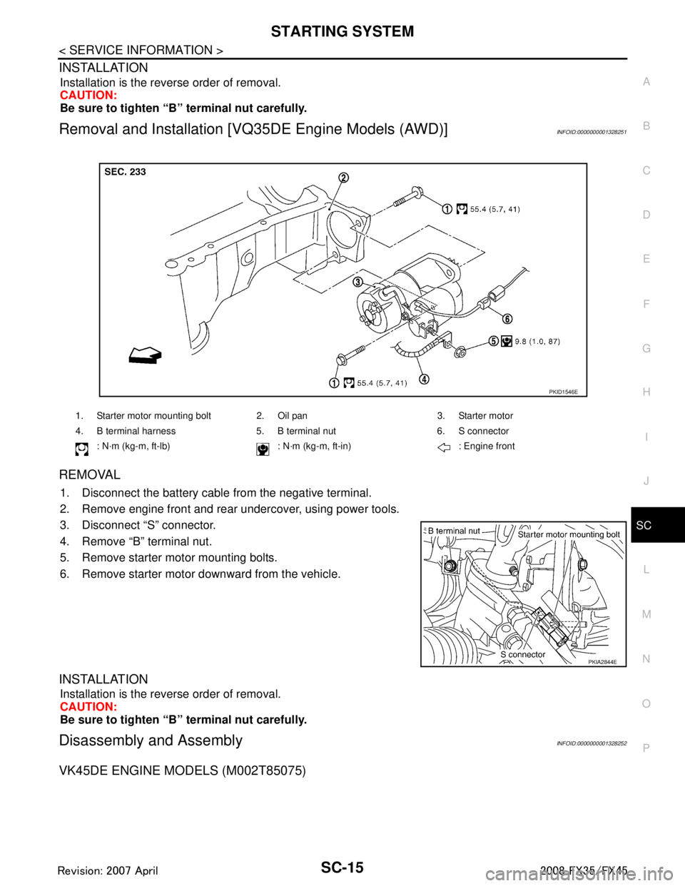
Removal and Installation [V Q35DE Engine Models (AWD)]INFOID:0000000001328251
REMOVAL
1. Disconnect the battery cabl e from the negative terminal.
2. Remove engine front and rear undercover, using power tools.
3. Disconnect “S” connector.
4. Remove “B” terminal nut.
5. Remove starter motor mounting bolts.
6. Remove starter motor downward from the vehicle.
INSTALLATION
Installation is the reverse order of removal.
CAUTION:
Be sure to tighten “B” terminal nut carefully.
Disassembly and AssemblyINFOID:0000000001328252
VK45DE ENGINE MODELS (M002T85075)
1. Starter motor mounting bolt 2. Oil pan 3. Starter motor
4. B terminal harness 5. B terminal nut 6. S connector
: N·m (kg-m, ft-lb) : N·m (k g-m, ft-in) : Engine front
PKID1546E
PKIA2844E
3AA93ABC3ACD3AC03ACA3AC03AC63AC53A913A773A893A873A873A8E3A773A983AC73AC93AC03AC3
3A893A873A873A8F3A773A9D3AAF3A8A3A8C3A863A9D3AAF3A8B3A8C