2008 INFINITI FX35 engine stall
[x] Cancel search: engine stallPage 3388 of 3924
PG-24
< SERVICE INFORMATION >
IPDM E/R (INTELLIGENT POWER DISTRIBUTION MODULE ENGINE ROOM)
OK or NG
OK >> GO TO 2.
NG >> If fuse or fusible link blown, be sure to e liminate cause of malfunction before installing new one.
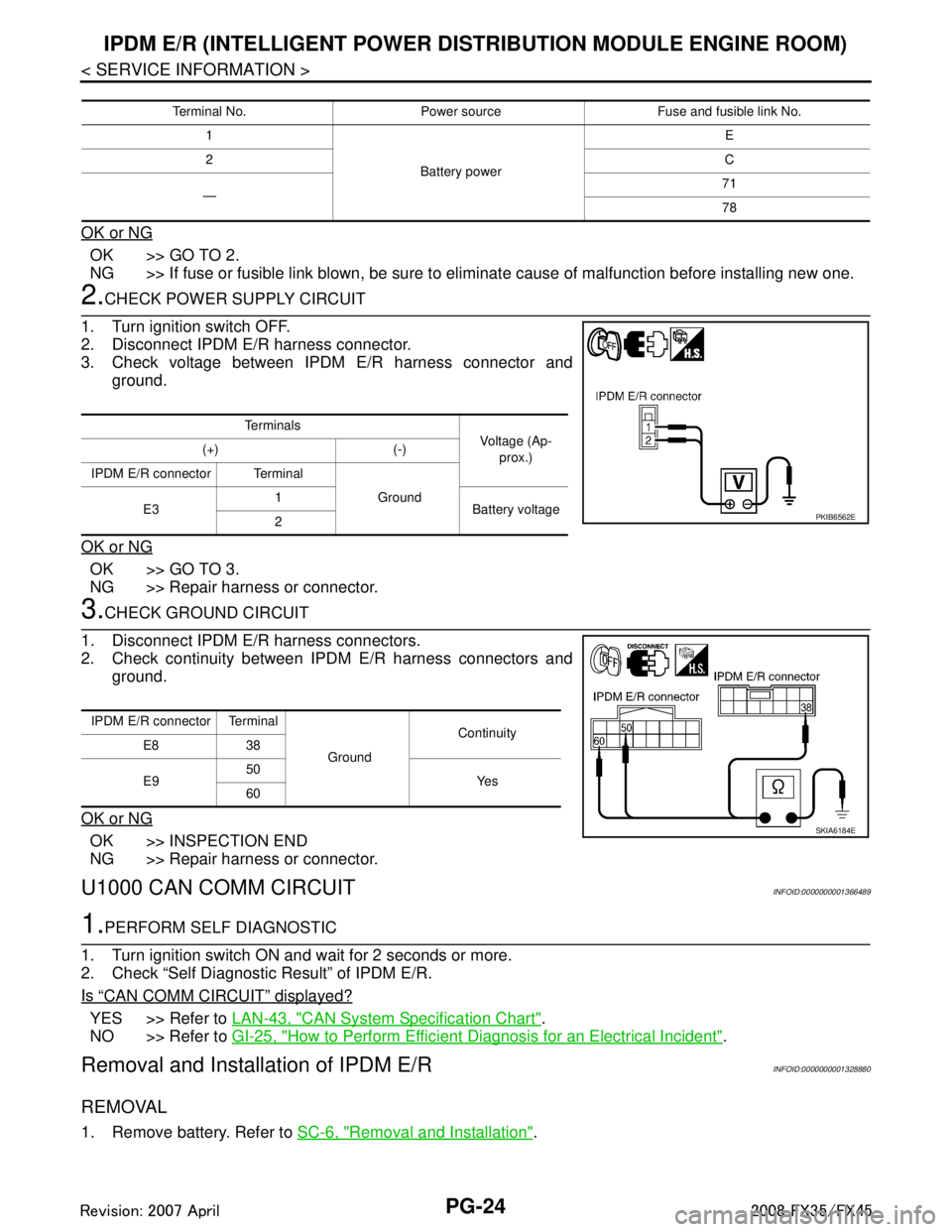
2.CHECK POWER SUPPLY CIRCUIT
1. Turn ignition switch OFF.
2. Disconnect IPDM E/R harness connector.
3. Check voltage between IPDM E/R harness connector and ground.
OK or NG
OK >> GO TO 3.
NG >> Repair harness or connector.
3.CHECK GROUND CIRCUIT
1. Disconnect IPDM E/R harness connectors.
2. Check continuity between IPDM E/R harness connectors and ground.
OK or NG
OK >> INSPECTION END
NG >> Repair harness or connector.
U1000 CAN COMM CIRCUITINFOID:0000000001366489
1.PERFORM SELF DIAGNOSTIC
1. Turn ignition switch ON and wait for 2 seconds or more.
2. Check “Self Diagnostic Result” of IPDM E/R.
Is
“CAN COMM CIRCUIT” displayed?
YES >> Refer to LAN-43, "CAN System Specification Chart".
NO >> Refer to GI-25, "
How to Perform Efficient Diagnosis for an Electrical Incident".
Removal and Installation of IPDM E/RINFOID:0000000001328880
REMOVAL
1. Remove battery. Refer to SC-6, "Removal and Installation".
Terminal No. Power source Fuse and fusible link No.
1
Battery power E
2 C
— 71
78
Te r m i n a l s
Voltage (Ap-
prox.)
(+) (-)
IPDM E/R connector Terminal Ground
E3 1
Battery voltage
2
PKIB6562E
IPDM E/R connector Terminal
GroundContinuity
E8 38
E9 50
Ye s
60
SKIA6184E
3AA93ABC3ACD3AC03ACA3AC03AC63AC53A913A773A893A873A873A8E3A773A983AC73AC93AC03AC3
3A893A873A873A8F3A773A9D3AAF3A8A3A8C3A863A9D3AAF3A8B3A8C
Page 3389 of 3924
IPDM E/R (INTELLIGENT POWER DISTRIBUTION MODULE ENGINE ROOM)
PG-25
< SERVICE INFORMATION >
C
D E
F
G H
I
J
L
M A
B
PG
N
O P
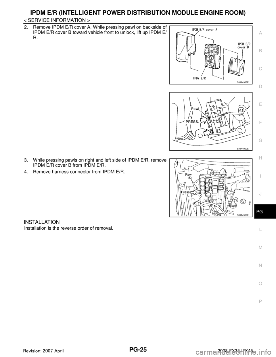
2. Remove IPDM E/R cover A. While pressing pawl on backside of IPDM E/R cover B toward vehicle front to unlock, lift up IPDM E/
R.
3. While pressing pawls on right and left side of IPDM E/R, remove IPDM E/R cover B from IPDM E/R.
4. Remove harness connector from IPDM E/R.
INSTALLATION
Installation is the reverse order of removal.
SKIA4968E
SKIA1902E
SKIA4969E
3AA93ABC3ACD3AC03ACA3AC03AC63AC53A913A773A893A873A873A8E3A773A983AC73AC93AC03AC3
3A893A873A873A8F3A773A9D3AAF3A8A3A8C3A863A9D3AAF3A8B3A8C
Page 3446 of 3924
PR-4
< SERVICE INFORMATION >
FRONT PROPELLER SHAFT
FRONT PROPELLER SHAFT
On-Vehicle InspectionINFOID:0000000001327466
APPEARANCE AND NOISE INSPECTION
Check the propeller shaft tube surface for dents or cracks. If damaged, replace propeller shaft assembly.
PROPELLER SHAFT VIBRATION
If vibration is present at high speed, inspect propeller shaft runout first.
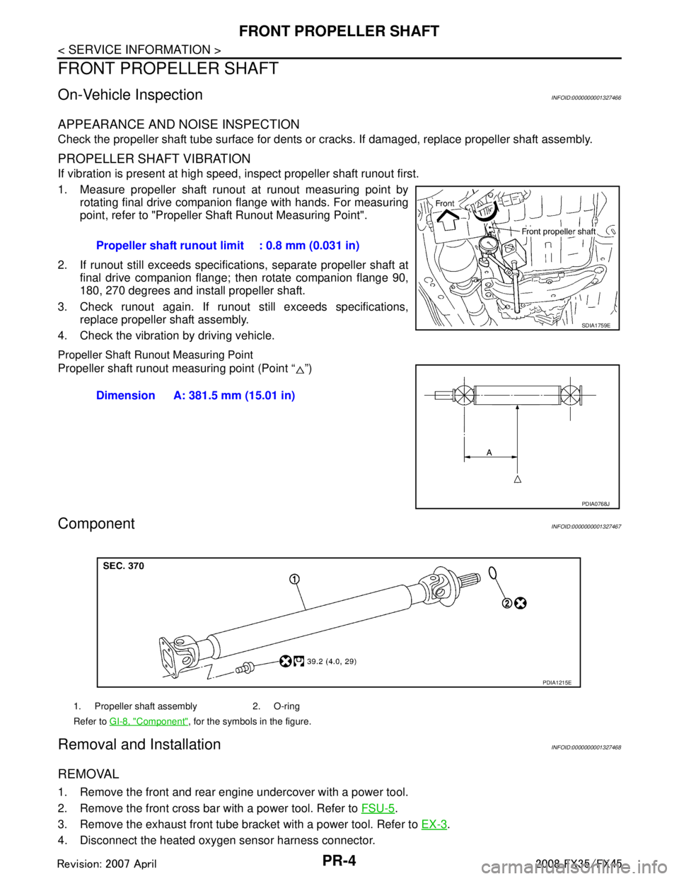
1. Measure propeller shaft runout at runout measuring point by rotating final drive companion flange with hands. For measuring
point, refer to "Propeller Shaft Runout Measuring Point".
2. If runout still exceeds specifications, separate propeller shaft at final drive companion flange; then rotate companion flange 90,
180, 270 degrees and install propeller shaft.
3. Check runout again. If runout still exceeds specifications, replace propeller shaft assembly.
4. Check the vibration by driving vehicle.
Propeller Shaft Runout Measuring Point
Propeller shaft runout measuring point (Point “ ”)
ComponentINFOID:0000000001327467
Removal and InstallationINFOID:0000000001327468
REMOVAL
1. Remove the front and rear engine undercover with a power tool.
2. Remove the front cross bar with a power tool. Refer to FSU-5
.
3. Remove the exhaust front tube bracket with a power tool. Refer to EX-3
.
4. Disconnect the heated oxygen sensor harness connector. Propeller shaft runout limit : 0.8 mm (0.031 in)
SDIA1759E
Dimension A: 381.5 mm (15.01 in)
PDIA0768J
1. Propeller shaft assembly 2. O-ring
Refer to
GI-8, "
Component", for the symbols in the figure.
PDIA1215E
3AA93ABC3ACD3AC03ACA3AC03AC63AC53A913A773A893A873A873A8E3A773A983AC73AC93AC03AC3
3A893A873A873A8F3A773A9D3AAF3A8A3A8C3A863A9D3AAF3A8B3A8C
Page 3447 of 3924
FRONT PROPELLER SHAFTPR-5
< SERVICE INFORMATION >
CEF
G H
I
J
K L
M A
B
PR
N
O P
5. Remove the exhaust front tube mounting nuts with a power tool. Refer to EX-3.
6. Remove the right bank three way catalyst with a power tool. Refer to EM-26, "
Removal and Installation"
(VQ35DE), EM-179, "Removal and Installation" (VK45DE).
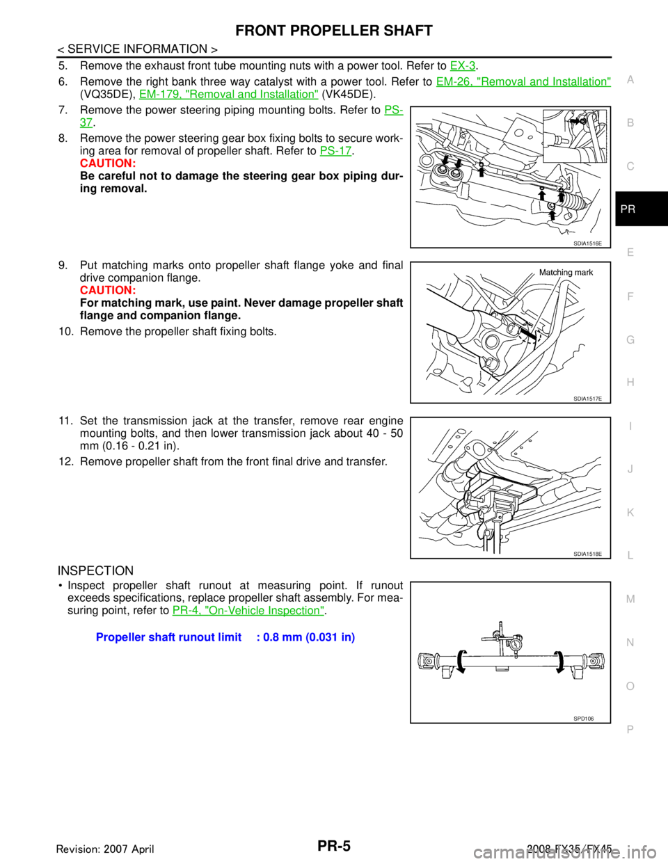
7. Remove the power steering piping mounting bolts. Refer to PS-
37.
8. Remove the power steering gear box fixing bolts to secure work- ing area for removal of propeller shaft. Refer to PS-17
.
CAUTION:
Be careful not to damage the steering gear box piping dur-
ing removal.
9. Put matching marks onto propeller shaft flange yoke and final drive companion flange.
CAUTION:
For matching mark, use paint. Never damage propeller shaft
flange and companion flange.
10. Remove the propeller shaft fixing bolts.
11. Set the transmission jack at the transfer, remove rear engine mounting bolts, and then lower transmission jack about 40 - 50
mm (0.16 - 0.21 in).
12. Remove propeller shaft from the front final drive and transfer.
INSPECTION
Inspect propeller shaft runout at measuring point. If runout exceeds specifications, replace propeller shaft assembly. For mea-
suring point, refer to PR-4, "
On-Vehicle Inspection".
SDIA1516E
SDIA1517E
SDIA1518E
Propeller shaft runout limit : 0.8 mm (0.031 in)
SPD106
3AA93ABC3ACD3AC03ACA3AC03AC63AC53A913A773A893A873A873A8E3A773A983AC73AC93AC03AC3
3A893A873A873A8F3A773A9D3AAF3A8A3A8C3A863A9D3AAF3A8B3A8C
Page 3464 of 3924
STEERING WHEELPS-9
< SERVICE INFORMATION >
C
DE
F
H I
J
K L
M A
B
PS
N
O P
STEERING WHEEL
On-Vehicle Inspection and ServiceINFOID:0000000001327712
CHECKING CONDITION OF INSTALLATION
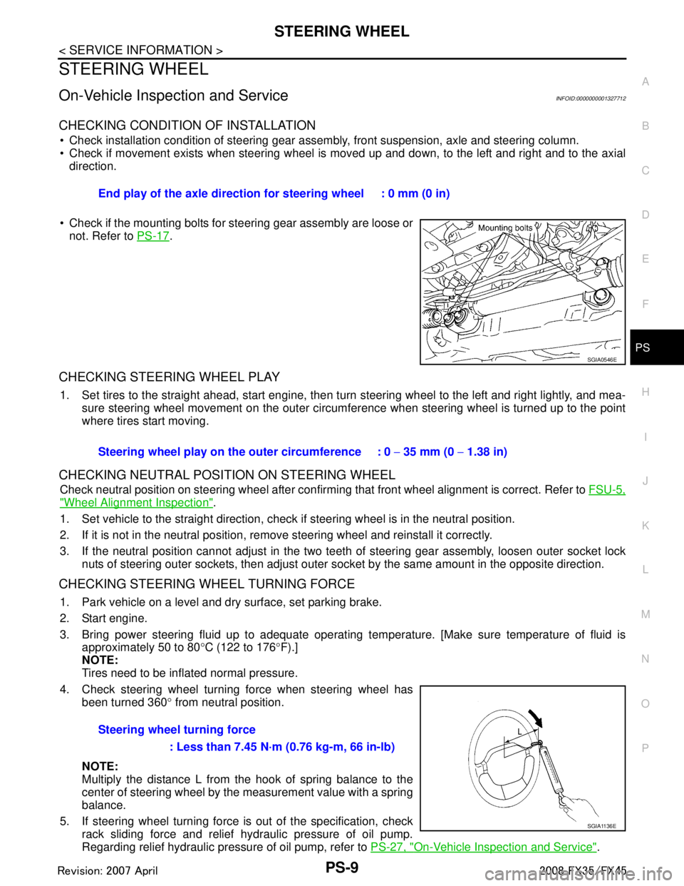
Check installation condition of steering gear assemb ly, front suspension, axle and steering column.
Check if movement exists when steering wheel is mo ved up and down, to the left and right and to the axial
direction.
Check if the mounting bolts for steering gear assembly are loose or not. Refer to PS-17
.
CHECKING STEERING WHEEL PLAY
1. Set tires to the straight ahead, start engine, then turn steering wheel to the left and right lightly, and mea-
sure steering wheel movement on the outer circumfe rence when steering wheel is turned up to the point
where tires start moving.
CHECKING NEUTRAL POSITION ON STEERING WHEEL
Check neutral position on steering wheel after confirming that front wheel alignment is correct. Refer to FSU-5,
"Wheel Alignment Inspection".
1. Set vehicle to the straight direction, chec k if steering wheel is in the neutral position.
2. If it is not in the neutral position, remo ve steering wheel and reinstall it correctly.
3. If the neutral position cannot adjust in the two teeth of steering gear assembly, loosen outer socket lock
nuts of steering outer sockets, then adjust outer so cket by the same amount in the opposite direction.
CHECKING STEERING WHEEL TURNING FORCE
1. Park vehicle on a level and dry surface, set parking brake.
2. Start engine.
3. Bring power steering fluid up to adequate operating te mperature. [Make sure temperature of fluid is
approximately 50 to 80 °C (122 to 176 °F).]
NOTE:
Tires need to be inflated normal pressure.
4. Check steering wheel turning force when steering wheel has been turned 360 ° from neutral position.
NOTE:
Multiply the distance L from the hook of spring balance to the
center of steering wheel by the measurement value with a spring
balance.
5. If steering wheel turning force is out of the specification, check
rack sliding force and relief hydraulic pressure of oil pump.
Regarding relief hydraulic pressure of oil pump, refer to PS-27, "
On-Vehicle Inspection and Service".
End play of the axle direction for steering wheel : 0 mm (0 in)
SGIA0546E
Steering wheel play on the
outer circumference : 0 − 35 mm (0 − 1.38 in)
Steering wheel turning force : Less than 7.45 N·m (0.76 kg-m, 66 in-lb)
SGIA1136E
3AA93ABC3ACD3AC03ACA3AC03AC63AC53A913A773A893A873A873A8E3A773A983AC73AC93AC03AC3
3A893A873A873A8F3A773A9D3AAF3A8A3A8C3A863A9D3AAF3A8B3A8C
Page 3465 of 3924
PS-10
< SERVICE INFORMATION >
STEERING WHEEL
a. Disconnect lower joint and steering knuckle from steering gear assembly. Refer to PS-12, "Removal and
Installation", FA X - 4 , "Removal and Installation", FAX-11, "Removal and Installation".
b. Start and run engine at idle to make sure steer ing fluid has reached normal operating temperature.
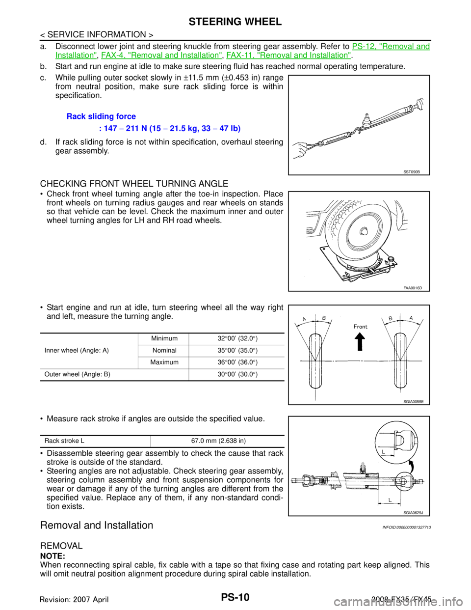
c. While pulling outer socket slowly in ±11.5 mm ( ±0.453 in) range
from neutral position, make sure rack sliding force is within
specification.
d. If rack sliding force is not within specification, overhaul steering gear assembly.
CHECKING FRONT WHEEL TURNING ANGLE
Check front wheel turning angle after the toe-in inspection. Placefront wheels on turning radius gauges and rear wheels on stands
so that vehicle can be level. Check the maximum inner and outer
wheel turning angles for LH and RH road wheels.
Start engine and run at idle, turn steering wheel all the way right and left, measure the turning angle.
Measure rack stroke if angles are outside the specified value.
Disassemble steering gear assembly to check the cause that rack
stroke is outside of the standard.
Steering angles are not adjustable. Check steering gear assembly, steering column assembly and front suspension components for
wear or damage if any of the turning angles are different from the
specified value. Replace any of them, if any non-standard condi-
tion exists.
Removal and InstallationINFOID:0000000001327713
REMOVAL
NOTE:
When reconnecting spiral cable, fix cable with a tape so that fixing case and rotating part keep aligned. This
will omit neutral position alignment procedure during spiral cable installation. Rack sliding force
: 147 − 211 N (15 − 21.5 kg, 33 − 47 lb)
SST090B
FAA0016D
Inner wheel (Angle: A) Minimum 32
°00’ (32.0 °)
Nominal 35 °00’ (35.0 °)
Maximum 36 °00’ (36.0 °)
Outer wheel (Angle: B) 30 °00’ (30.0 °)
SGIA0055E
Rack stroke L 67.0 mm (2.638 in)
SGIA0629J
3AA93ABC3ACD3AC03ACA3AC03AC63AC53A913A773A893A873A873A8E3A773A983AC73AC93AC03AC3
3A893A873A873A8F3A773A9D3AAF3A8A3A8C3A863A9D3AAF3A8B3A8C
Page 3483 of 3924
PS-28
< SERVICE INFORMATION >
POWER STEERING OIL PUMP
Before starting work, confirm belt tension is proper.
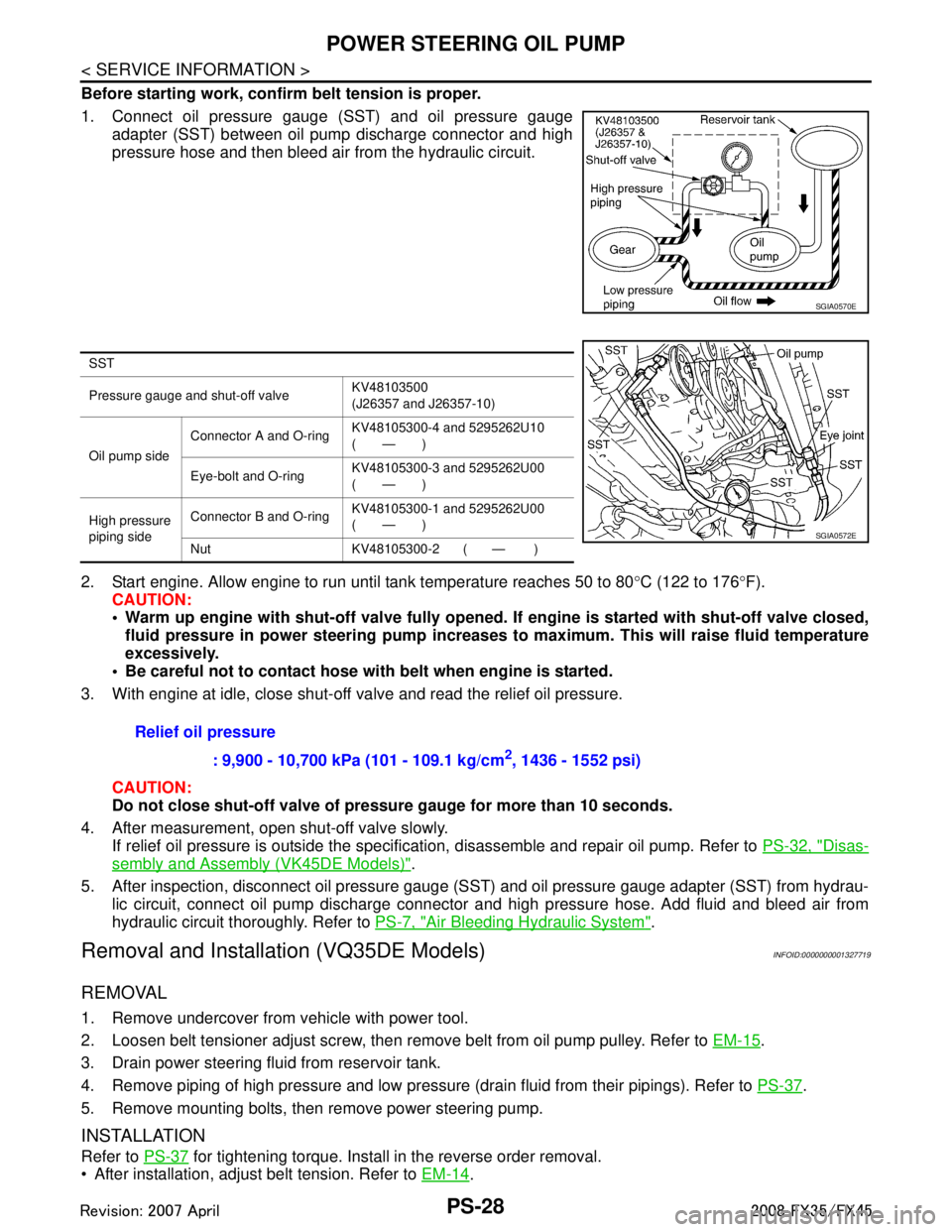
1. Connect oil pressure gauge (SST) and oil pressure gaugeadapter (SST) between oil pump discharge connector and high
pressure hose and then bleed air from the hydraulic circuit.
2. Start engine. Allow engine to run until tank temperature reaches 50 to 80 °C (122 to 176 °F).
CAUTION:
Warm up engine with shut-off val ve fully opened. If engine is started with shut-off valve closed,
fluid pressure in power steering pump increases to maximum. This will raise fluid temperature
excessively.
Be careful not to contact hose with belt when engine is started.
3. With engine at idle, close shut-off valve and read the relief oil pressure.
CAUTION:
Do not close shut-off valve of pressu re gauge for more than 10 seconds.
4. After measurement, open shut-off valve slowly. If relief oil pressure is outside the specification, disassemble and repair oil pump. Refer to PS-32, "
Disas-
sembly and Assembly (VK45DE Models)".
5. After inspection, disconnect oil pressure gauge (S ST) and oil pressure gauge adapter (SST) from hydrau-
lic circuit, connect oil pump discharge connector and high pressure hose. Add fluid and bleed air from
hydraulic circuit thoroughly. Refer to PS-7, "
Air Bleeding Hydraulic System".
Removal and Installation (VQ35DE Models)INFOID:0000000001327719
REMOVAL
1. Remove undercover from vehicle with power tool.
2. Loosen belt tensioner adjust screw, then remove belt from oil pump pulley. Refer to EM-15
.
3. Drain power steering fluid from reservoir tank.
4. Remove piping of high pressure and low pressure (drain fluid from their pipings). Refer to PS-37
.
5. Remove mounting bolts, then remove power steering pump.
INSTALLATION
Refer to PS-37 for tightening torque. Install in the reverse order removal.
After installation, adjust belt tension. Refer to EM-14
.
SGIA0570E
SST
Pressure gauge and shut-off valveKV48103500
(J26357 and J26357-10)
Oil pump side Connector A and O-ring
KV48105300-4 and 5295262U10
(—)
Eye-bolt and O-ring KV48105300-3 and 5295262U00
(—)
High pressure
piping side Connector B and O-ring
KV48105300-1 and 5295262U00
(—)
Nut KV48105300-2 ( — )
SGIA0572E
Relief oil pressure : 9,900 - 10,700 kPa (101 - 109.1 kg/cm
2, 1436 - 1552 psi)
3AA93ABC3ACD3AC03ACA3AC03AC63AC53A913A773A893A873A873A8E3A773A983AC73AC93AC03AC3
3A893A873A873A8F3A773A9D3AAF3A8A3A8C3A863A9D3AAF3A8B3A8C
Page 3484 of 3924
POWER STEERING OIL PUMPPS-29
< SERVICE INFORMATION >
C
DE
F
H I
J
K L
M A
B
PS
N
O P
After installation, bleed air. Refer to PS-7, "Air Bleeding Hydraulic System".
Removal and Installation (VK45DE Models)INFOID:0000000001327720
REMOVAL
1. Remove undercover from vehicle with power tool.
2. Remove power steering oil pump belt from auto tensioner. Refer to EM-170
.
3. Drain power steering fluid from reservoir tank.
4. Remove piping of high pressure and low pressure from power steering oil pump (drain fluid from their pip- ings). Refer to PS-37
.
5. Remove mounting bolts, then remove power steering pump.
INSTALLATION
Refer to PS-37 for tightening torque. Install in the reverse order removal.
After installation, bleed air. Refer to PS-7, "
Air Bleeding Hydraulic System".
NOTE:
Adjustment of belt tension is no necessary bec ause engine of this model equips auto tensioner.
Disassembly and Assembly (VQ35DE Models)INFOID:0000000001327721
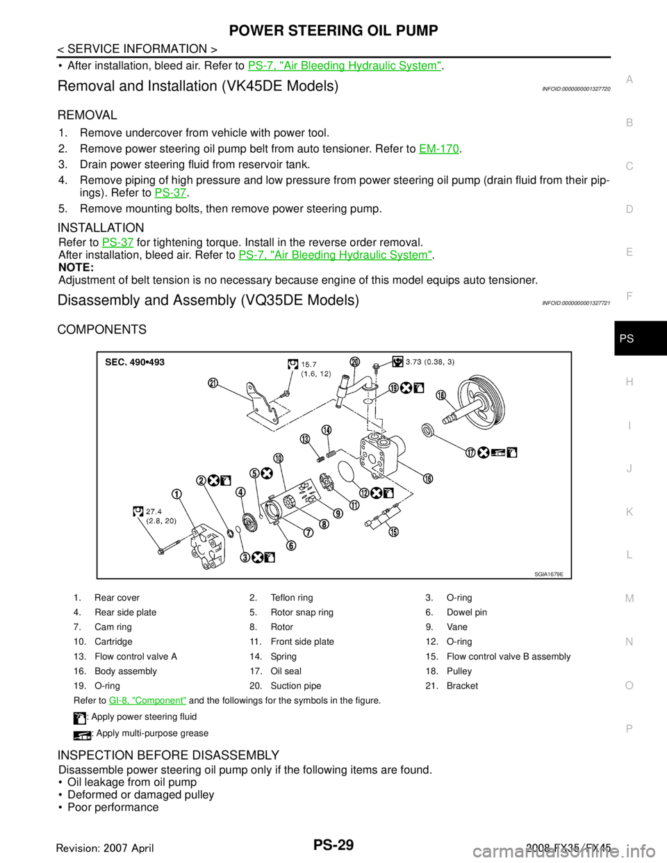
COMPONENTS
INSPECTION BEFORE DISASSEMBLY
Disassemble power steering oil pump only if the following items are found.
Oil leakage from oil pump
Deformed or damaged pulley
Poor performance
1. Rear cover 2. Teflon ring 3. O-ring
4. Rear side plate 5. Rotor snap ring 6. Dowel pin
7. Cam ring 8. Rotor 9. Vane
10. Cartridge 11. Front side plate 12. O-ring
13. Flow control valve A 14. Spring 15. Flow control valve B assembly
16. Body assembly 17. Oil seal 18. Pulley
19. O-ring 20. Suction pipe 21. Bracket
Refer to GI-8, "
Component" and the followings for the symbols in the figure.
: Apply power steering fluid
: Apply multi-purpose grease
SGIA1679E
3AA93ABC3ACD3AC03ACA3AC03AC63AC53A913A773A893A873A873A8E3A773A983AC73AC93AC03AC3
3A893A873A873A8F3A773A9D3AAF3A8A3A8C3A863A9D3AAF3A8B3A8C