2008 INFINITI FX35 service
[x] Cancel search: servicePage 3871 of 3924
TROUBLE DIAGNOSIS FOR SYMPTOMSWT-31
< SERVICE INFORMATION >
C
DF
G H
I
J
K L
M A
B
WT
N
O P
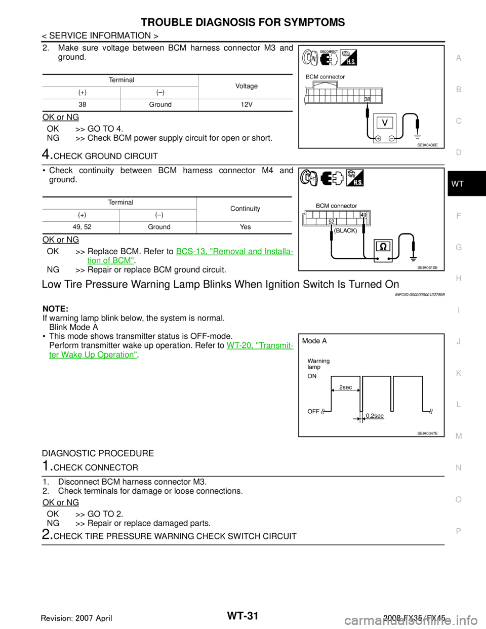
2. Make sure voltage between BCM harness connector M3 and ground.
OK or NG
OK >> GO TO 4.
NG >> Check BCM power supply circuit for open or short.
4.CHECK GROUND CIRCUIT
Check continuity between BCM harness connector M4 and ground.
OK or NG
OK >> Replace BCM. Refer to BCS-13, "Removal and Installa-
tion of BCM".
NG >> Repair or replace BCM ground circuit.
Low Tire Pressure Warning Lamp Blin ks When Ignition Switch Is Turned On
INFOID:0000000001327595
NOTE:
If warning lamp blink below, the system is normal.
Blink Mode A
This mode shows transmitter status is OFF-mode.
Perform transmitter wake up operation. Refer to WT-20, "
Transmit-
ter Wake Up Operation".
DIAGNOSTIC PROCEDURE
1.CHECK CONNECTOR
1. Disconnect BCM harness connector M3.
2. Check terminals for damage or loose connections.
OK or NG
OK >> GO TO 2.
NG >> Repair or replace damaged parts.
2.CHECK TIRE PRESSURE WA RNING CHECK SWITCH CIRCUIT
Te r m i n a l
Voltag e
(+) (–)
38 Ground 12V
SEIA0436E
Te r m i n a l Continuity
(+) (–)
49, 52 Ground Yes
SEIA0610E
SEIA0347E
3AA93ABC3ACD3AC03ACA3AC03AC63AC53A913A773A893A873A873A8E3A773A983AC73AC93AC03AC3
3A893A873A873A8F3A773A9D3AAF3A8A3A8C3A863A9D3AAF3A8B3A8C
Page 3872 of 3924
WT-32
< SERVICE INFORMATION >
TROUBLE DIAGNOSIS FOR SYMPTOMS
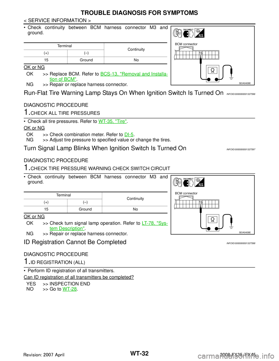
Check continuity between BCM harness connector M3 andground.
OK or NG
OK >> Replace BCM. Refer to BCS-13, "Removal and Installa-
tion of BCM".
NG >> Repair or replace harness connector.
Run-Flat Tire Warning Lamp Stays On When Ignition Switch Is Turned OnINFOID:0000000001327596
DIAGNOSTIC PROCEDURE
1.CHECK ALL TIRE PRESSURES
Check all tire pressures. Refer to WT-35, "
Tire".
OK or NG
OK >> Check combination meter. Refer to DI-5.
NG >> Adjust tire pressure to specified value or change the tires.
Turn Signal Lamp Blinks When Ignition Switch Is Turned OnINFOID:0000000001327597
DIAGNOSTIC PROCEDURE
1.CHECK TIRE PRESSURE WARNI NG CHECK SWITCH CIRCUIT
Check continuity between BCM harness connector M3 and ground.
OK or NG
OK >> Check turn signal lamp operation. Refer to LT-78, "Sys-
tem Description".
NG >> Repair or replace harness connector.
ID Registration Ca nnot Be CompletedINFOID:0000000001327598
DIAGNOSTIC PROCEDURE
1.ID REGISTRATION (ALL)
Perform ID registration of all transmitters.
Can ID registration of all transmitters be completed?
YES >> INSPECTION END
NO >> Go to WT-28
.
Te r m i n a l
Continuity
(+) (–)
15 Ground No
SEIA0438E
Te r m i n a l Continuity
(+) (–)
15 Ground No
SEIA0438E
3AA93ABC3ACD3AC03ACA3AC03AC63AC53A913A773A893A873A873A8E3A773A983AC73AC93AC03AC3
3A893A873A873A8F3A773A9D3AAF3A8A3A8C3A863A9D3AAF3A8B3A8C
Page 3873 of 3924
REMOVAL AND INSTALLATIONWT-33
< SERVICE INFORMATION >
C
DF
G H
I
J
K L
M A
B
WT
N
O P
REMOVAL AND INSTALLATION
TransmitterINFOID:0000000001327599
REMOVAL
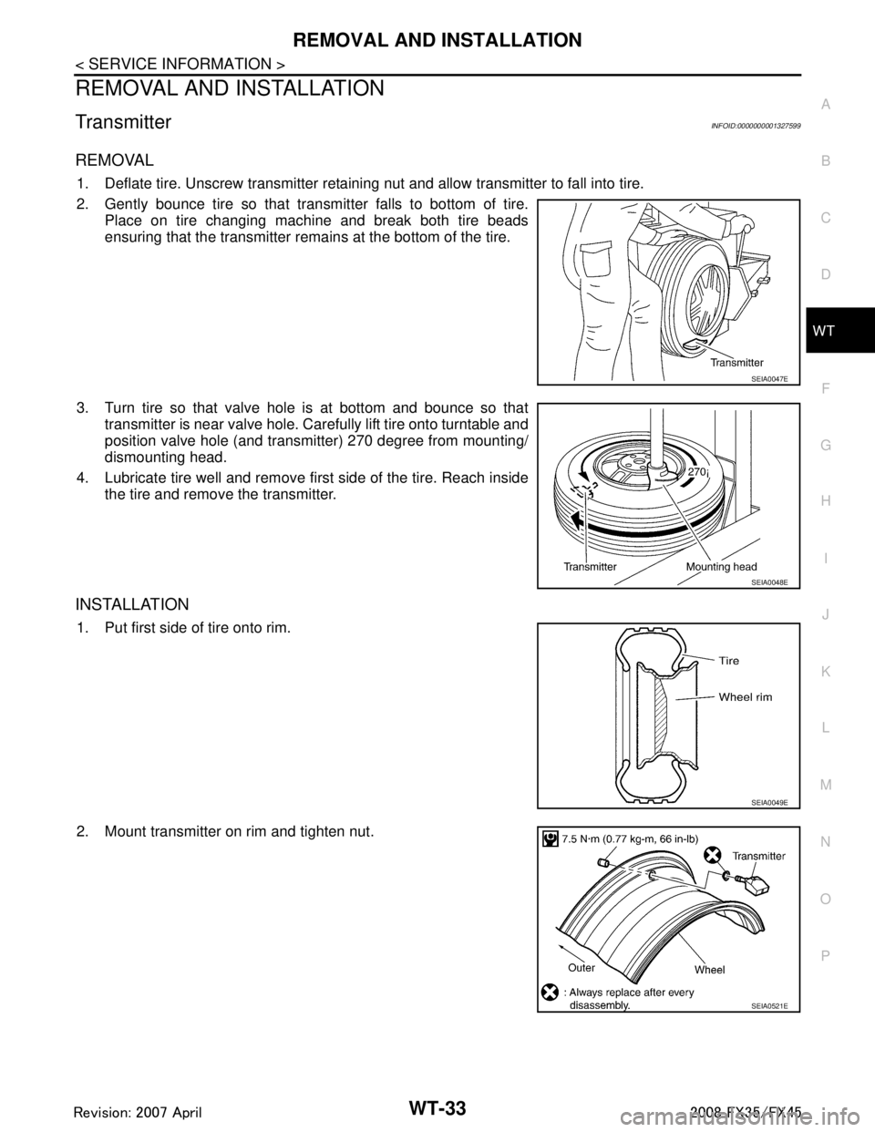
1. Deflate tire. Unscrew transmitter retaining nut and allow transmitter to fall into tire.
2. Gently bounce tire so that transmitter falls to bottom of tire. Place on tire changing machine and break both tire beads
ensuring that the transmitter rema ins at the bottom of the tire.
3. Turn tire so that valve hole is at bottom and bounce so that transmitter is near valve hole. Carefully lift tire onto turntable and
position valve hole (and transmitter) 270 degree from mounting/
dismounting head.
4. Lubricate tire well and remove first side of the tire. Reach inside the tire and remove the transmitter.
INSTALLATION
1. Put first side of tire onto rim.
2. Mount transmitter on rim and tighten nut.
SEIA0047E
SEIA0048E
SEIA0049E
SEIA0521E
3AA93ABC3ACD3AC03ACA3AC03AC63AC53A913A773A893A873A873A8E3A773A983AC73AC93AC03AC3
3A893A873A873A8F3A773A9D3AAF3A8A3A8C3A863A9D3AAF3A8B3A8C
Page 3874 of 3924
WT-34
< SERVICE INFORMATION >
REMOVAL AND INSTALLATION
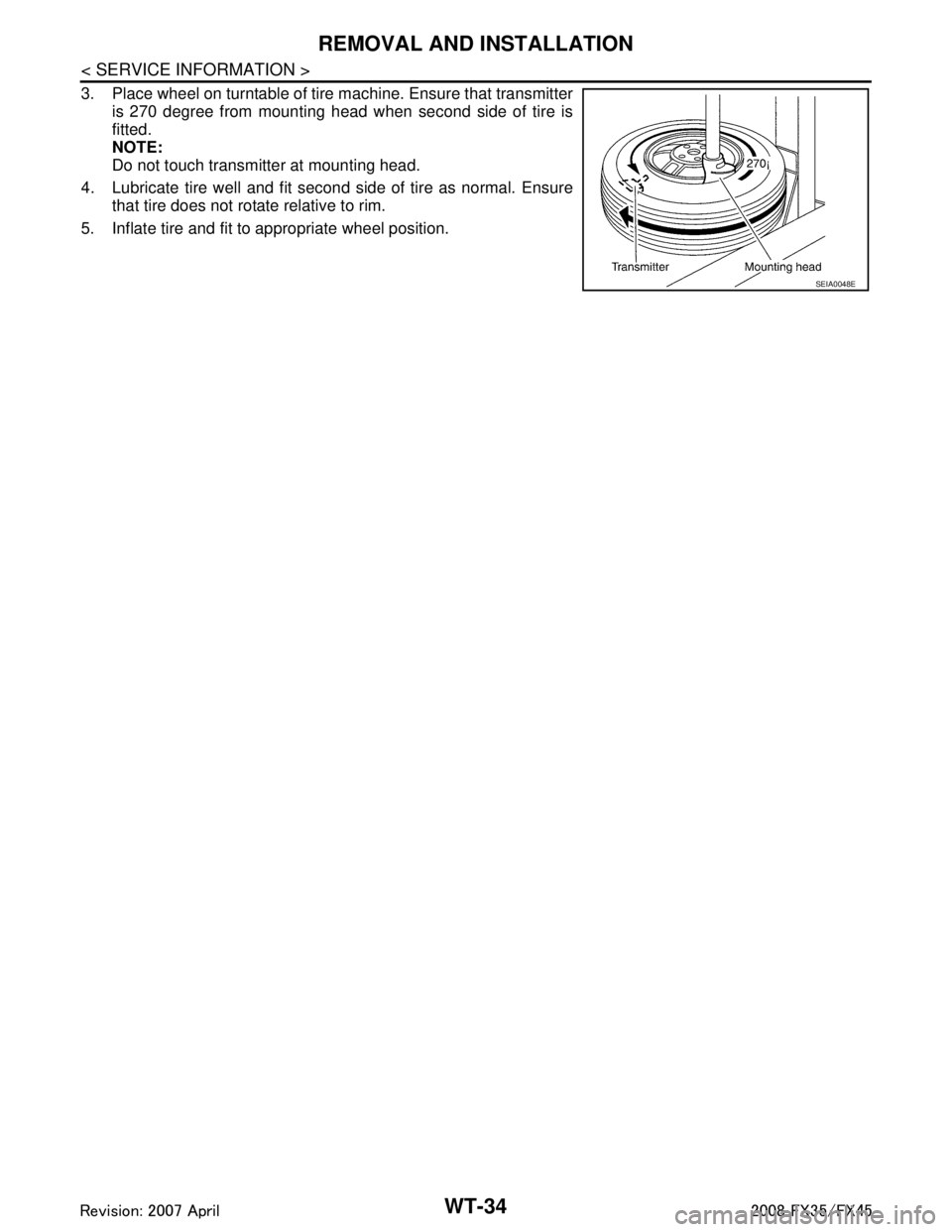
3. Place wheel on turntable of tire machine. Ensure that transmitteris 270 degree from mounting head when second side of tire is
fitted.
NOTE:
Do not touch transmitter at mounting head.
4. Lubricate tire well and fit second side of tire as normal. Ensure that tire does not rotate relative to rim.
5. Inflate tire and fit to appropriate wheel position.
SEIA0048E
3AA93ABC3ACD3AC03ACA3AC03AC63AC53A913A773A893A873A873A8E3A773A983AC73AC93AC03AC3
3A893A873A873A8F3A773A9D3AAF3A8A3A8C3A863A9D3AAF3A8B3A8C
Page 3875 of 3924

SERVICE DATA AND SPECIFICATIONS (SDS)
WT-35
< SERVICE INFORMATION >
C
D F
G H
I
J
K L
M A
B
WT
N
O P
SERVICE DATA AND SPECIFICATIONS (SDS)
Road WheelINFOID:0000000001327600
TireINFOID:0000000001327601
Unit: kPa (kg/cm2, psi)
Kind of wheel Aluminum Steel (for emergency use)
Maximum radial runout limit Lateral deflection Less than 0.3 mm (0.012 in) Less than 1.5 mm (0.059 in)
Vertical deflection Less than 0.3 mm (0.012 in) Less than 1.5 mm (0.059 in)
Maximum allowable unbalance Dynamic (At rim flange) Less than 5.0 g (0.2 oz) (one side) —
Static (At rim flange) Less than 20 g (0.7 oz) —
Tire size Air pressure
Front Rear
P265/60R18 109V 220 (2.2, 32) 220 (2.2, 32)
P265/50R20 106V 220 (2.2, 32) 220 (2.2, 32)
T175/90D18 110M 420 (4.2, 60) 420 (4.2, 60)
3AA93ABC3ACD3AC03ACA3AC03AC63AC53A913A773A893A873A873A8E3A773A983AC73AC93AC03AC3
3A893A873A873A8F3A773A9D3AAF3A8A3A8C3A863A9D3AAF3A8B3A8C
Page 3876 of 3924

WW-1
ELECTRICAL
C
DE
F
G H
I
J
L
M
SECTION WW
A
B
WW
N
O P
CONTENTS
WIPER, WASHER & HORN
SERVICE INFORMATION .. ..........................3
PRECAUTION ................................................ .....3
Precaution for Supplemental Restraint System
(SRS) "AIR BAG" and "SEAT BELT PRE-TEN-
SIONER" ............................................................. ......
3
Precaution for Procedure without Cowl Top Cover ......3
FRONT WIPER AND WASHER SYSTEM ..........4
Component Parts and Harness Connector Loca-
tion ...................................................................... ......
4
System Description ...................................................4
CAN Communication System Description .................6
CAN Communication Unit .........................................7
Schematic .................................................................7
Wiring Diagram - WIPER - ........................................8
Terminal and Reference Value for BCM .................10
Terminal and Reference Value for IPDM E/R .........14
How to Proceed with Trouble Diagnosis .................14
Preliminary Check ...................................................14
CONSULT-III Functions (BCM) ...............................15
CONSULT-III Functions (IPDM E/R) .......................16
Front Wiper Does Not Operate ...............................17
Front Wiper Does Not Return to Stop Position .......18
Only Front Wiper Low Does Not Operate ...............19
Only Front Wiper High Does Not Operate ...............20
Only Front Wiper Intermittent Does Not Operate ....21
Front Wiper Interval Time Is Not Controlled by Ve-
hicle Speed .............................................................
21
Front Wiper Intermittent Operation Switch Posi-
tion Cannot Be Adjusted .........................................
22
Wiper Does Not Wipe When Front Washer Oper-
ates .........................................................................
22
After Front Wiper Operate for 10 Seconds, They
Stop for 20 Seconds, and After Repeating the Op-
eration Five Times, They Become Inoperative ........
22
Front Wiper Does Not Stop .....................................23
Removal and Installation of Front Wiper Arms, Ad-
justment of Wiper Arms Stop Location ....................
23
Removal and Installation of Front Wiper Drive As-
sembly ................................................................. ....
24
Disassembly and Assembly of Front Wiper Drive
Assembly ............................................................. ....
25
Washer Nozzle Adjustment .....................................25
Washer Tube Layout ...............................................27
Removal and Installation of Front Washer Nozzle ....27
Removal and Installation of Front Washer Tube
Joint .........................................................................
27
Inspection of Washer Nozzle ...................................27
Inspection of Front Wiper and Washer Switch Cir-
cuit ...........................................................................
28
Removal and Installation of Front Wiper and
Washer Switch .........................................................
28
Removal and Installation of Washer Tank ...............28
Removal and Installation of Front and Rear Wash-
er Pump ...................................................................
29
REAR WIPER AND WASHER SYSTEM ..........30
Component Parts and Harness Connector Loca-
tion ...........................................................................
30
System Description ..................................................30
Wiring Diagram - WIP/ R - .......................................32
Terminal and Reference Value for BCM ..................33
How to Proceed with Trouble Diagnosis ..................35
Preliminary Check ...................................................36
CONSULT-III Functions (BCM) ...............................36
Rear Wiper Does Not Operate ................................37
Rear Wiper Does Not Return to Stop Position ........39
Only Rear Wiper ON Does Not Operate ..................40
Only Rear Wiper INT Does Not Operate .................40
Wiper Does Not Wipe When Rear Washer Oper-
ates ..........................................................................
40
Rear Wipers Do Not Stop ........................................40
Removal and Installation of Rear Wiper Arm, Ad-
justment of Wiper Arms Stop Location ....................
40
Removal and Installation of Rear Wiper Blade ........41
Removal and Installation of Rear Wiper Motor ........42
Washer Nozzle Adjustment .....................................43
Washer Tube Layout ...............................................43
Removal and Installation of Washer Nozzle ............43
Check Valve ............................................................44
3AA93ABC3ACD3AC03ACA3AC03AC63AC53A913A773A893A873A873A8E3A773A983AC73AC93AC03AC3
3A893A873A873A8F3A773A9D3AAF3A8A3A8C3A863A9D3AAF3A8B3A8C
Page 3878 of 3924
PRECAUTIONWW-3
< SERVICE INFORMATION >
C
DE
F
G H
I
J
L
M A
B
WW
N
O P
SERVICE INFORMATION
PRECAUTION
Precaution for Supplemental Restraint System (SRS) "AIR BAG" and "SEAT BELT
PRE-TENSIONER"
INFOID:0000000001612916
The Supplemental Restraint System such as “A IR BAG” and “SEAT BELT PRE-TENSIONER”, used along
with a front seat belt, helps to reduce the risk or severi ty of injury to the driver and front passenger for certain
types of collision. This system includes seat belt switch inputs and dual stage front air bag modules. The SRS
system uses the seat belt switches to determine the front air bag deployment, and may only deploy one front
air bag, depending on the severity of a collision and whether the front occupants are belted or unbelted.
Information necessary to service the system safely is included in the “SUPPLEMENTAL RESTRAINT SYS-
TEM” and “SEAT BELTS” of this Service Manual.
WARNING:
• To avoid rendering the SRS inoper ative, which could increase the risk of personal injury or death in
the event of a collision which would result in air bag inflation, all maintenance must be performed by
an authorized NISSAN/INFINITI dealer.
Improper maintenance, including in correct removal and installation of the SRS, can lead to personal
injury caused by unintentional act ivation of the system. For removal of Spiral Cable and Air Bag
Module, see the “SUPPLEMEN TAL RESTRAINT SYSTEM”.
Do not use electrical test equipm ent on any circuit related to the SRS unless instructed to in this
Service Manual. SRS wiring harnesses can be identi fied by yellow and/or orange harnesses or har-
ness connectors.
Precaution for Procedur e without Cowl Top CoverINFOID:0000000001612917
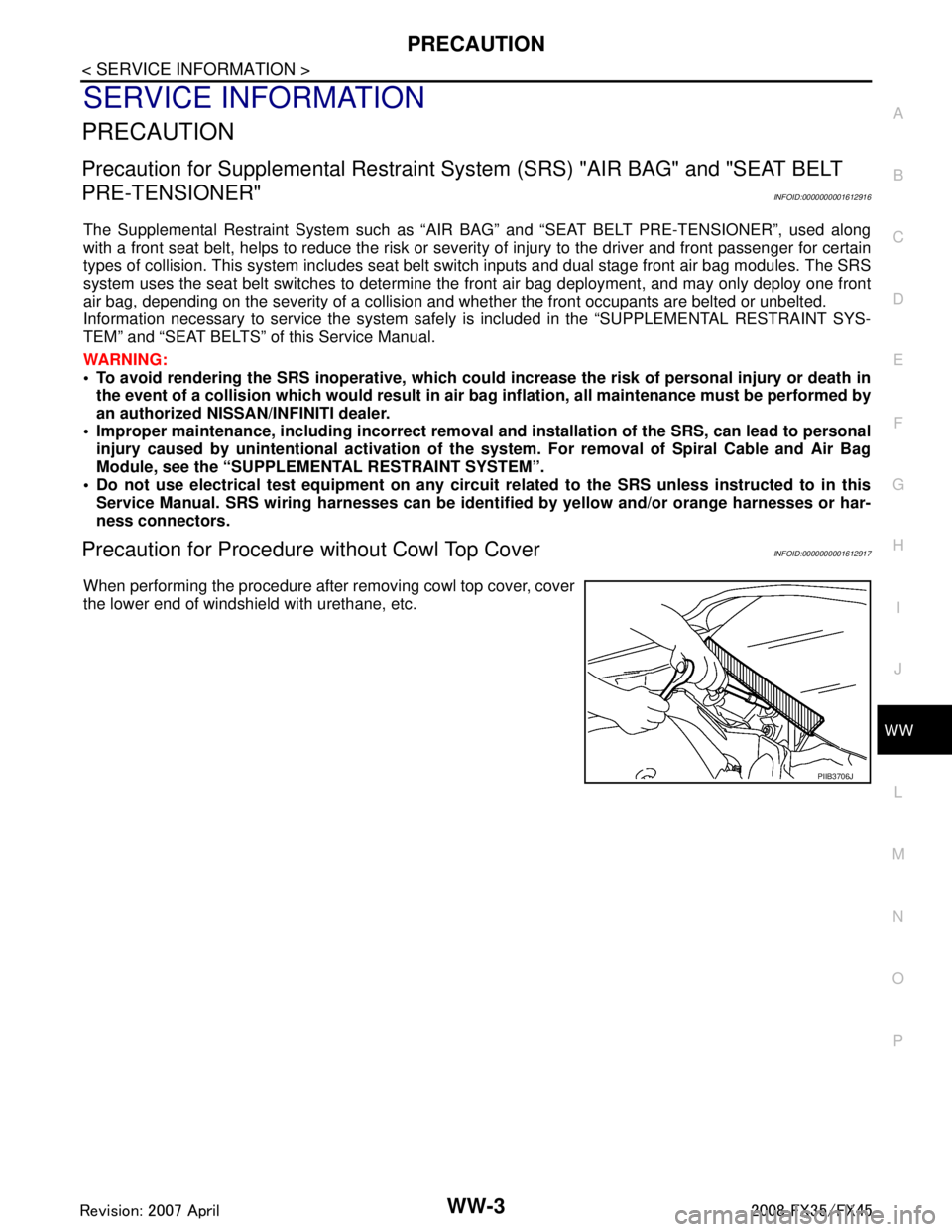
When performing the procedure after removing cowl top cover, cover
the lower end of windshield with urethane, etc.
PIIB3706J
3AA93ABC3ACD3AC03ACA3AC03AC63AC53A913A773A893A873A873A8E3A773A983AC73AC93AC03AC3
3A893A873A873A8F3A773A9D3AAF3A8A3A8C3A863A9D3AAF3A8B3A8C
Page 3879 of 3924
WW-4
< SERVICE INFORMATION >
FRONT WIPER AND WASHER SYSTEM
FRONT WIPER AND WASHER SYSTEM
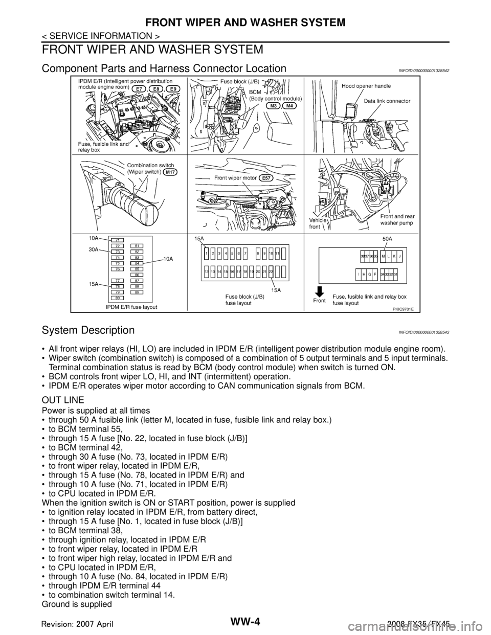
Component Parts and Harness Connector LocationINFOID:0000000001328542
System DescriptionINFOID:0000000001328543
All front wiper relays (HI, LO) are included in IPDM E/R (intelligent power distribution module engine room).
Wiper switch (combination switch) is composed of a combination of 5 output terminals and 5 input terminals.
Terminal combination status is read by BCM ( body control module) when switch is turned ON.
BCM controls front wiper LO, HI, and INT (intermittent) operation.
IPDM E/R operates wiper motor according to CAN communication signals from BCM.
OUT LINE
Power is supplied at all times
through 50 A fusible link (letter M, located in fuse, fusible link and relay box.)
to BCM terminal 55,
through 15 A fuse [No. 22, located in fuse block (J/B)]
to BCM terminal 42,
through 30 A fuse (No. 73, located in IPDM E/R)
to front wiper relay, located in IPDM E/R,
through 15 A fuse (No. 78, located in IPDM E/R) and
through 10 A fuse (No. 71, located in IPDM E/R)
to CPU located in IPDM E/R.
When the ignition switch is ON or START position, power is supplied
to ignition relay located in IPDM E/R, from battery direct,
through 15 A fuse [No. 1, located in fuse block (J/B)]
to BCM terminal 38,
through ignition relay, located in IPDM E/R
to front wiper relay, located in IPDM E/R
to front wiper high relay, located in IPDM E/R and
to CPU located in IPDM E/R,
through 10 A fuse (No. 84, located in IPDM E/R)
through IPDM E/R terminal 44
to combination switch terminal 14.
Ground is supplied
PKIC9701E
3AA93ABC3ACD3AC03ACA3AC03AC63AC53A913A773A893A873A873A8E3A773A983AC73AC93AC03AC3
3A893A873A873A8F3A773A9D3AAF3A8A3A8C3A863A9D3AAF3A8B3A8C