Page 3655 of 3924
SE-16
< SERVICE INFORMATION >
AUTOMATIC DRIVE POSITIONER
Component Parts and Harn ess Connector Location
INFOID:0000000001328098
PIIB8565E
3AA93ABC3ACD3AC03ACA3AC03AC63AC53A913A773A893A873A873A8E3A773A983AC73AC93AC03AC3
3A893A873A873A8F3A773A9D3AAF3A8A3A8C3A863A9D3AAF3A8B3A8C
Page 3656 of 3924

AUTOMATIC DRIVE POSITIONERSE-17
< SERVICE INFORMATION >
C
DE
F
G H
J
K L
M A
B
SE
N
O P
CAN Communication System DescriptionINFOID:0000000001328099
CAN (Controller Area Network) is a serial communication li ne for real time application. It is an on-vehicle mul-
tiplex communication line with high data communication speed and excellent error detection ability. Many elec-
tronic control units are equipped onto a vehicle, and each control unit shares information and links with other
control units during operation (not independent). In CAN communication, control units are connected with 2
communication lines (CAN H line, CAN L line) allowing a high rate of information transmission with less wiring.
Each control unit transmits/receives data but selectively reads required data only.
CAN Communication UnitINFOID:0000000001328100
Refer to LAN-43, "CAN System Specification Chart".
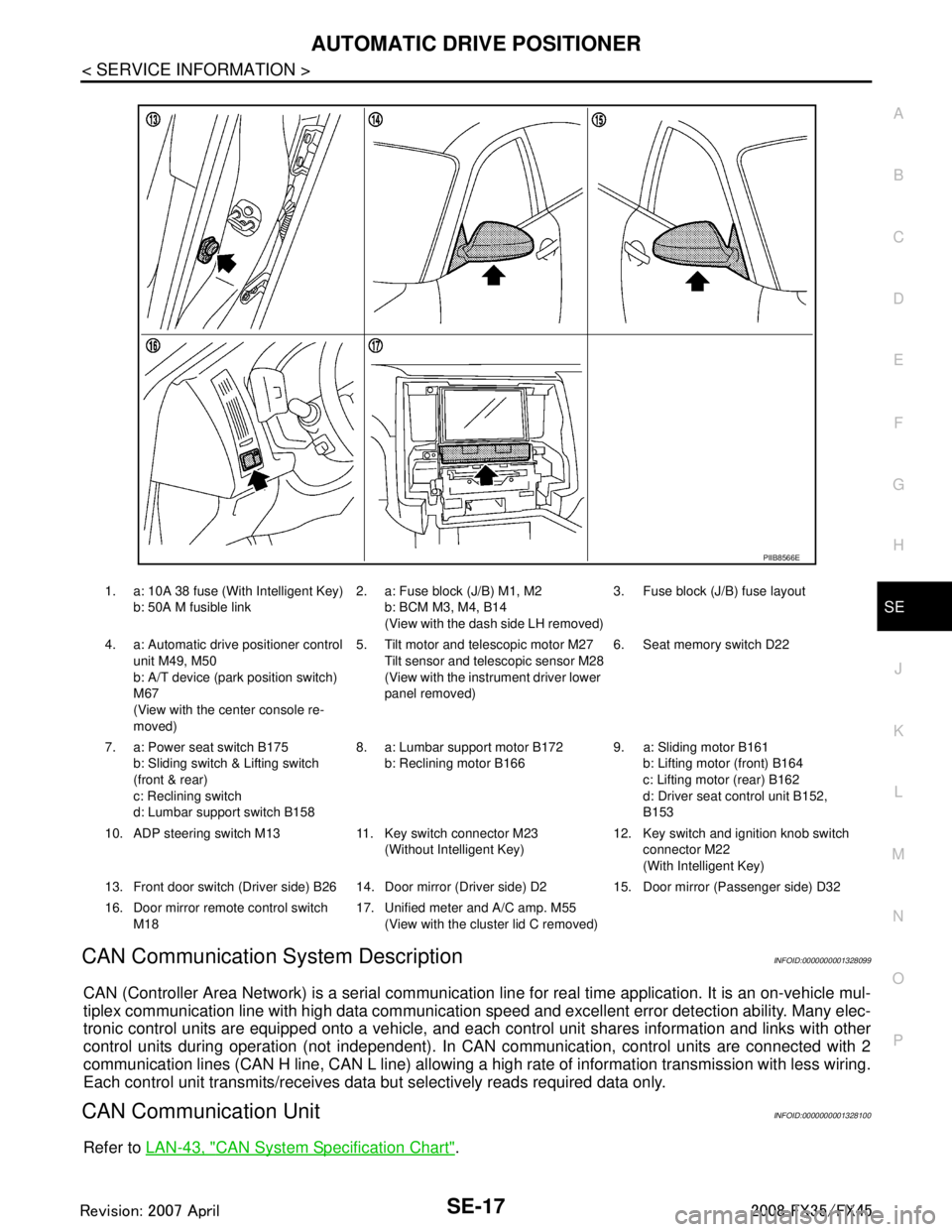
1. a: 10A 38 fuse (With Intelligent Key)
b: 50A M fusible link 2. a: Fuse block (J/B) M1, M2
b: BCM M3, M4, B14
(View with the dash side LH removed) 3. Fuse block (J/B) fuse layout
4. a: Automatic drive positioner control unit M49, M50
b: A/T device (park position switch)
M67
(View with the center console re-
moved) 5. Tilt motor and telescopic motor M27
Tilt sensor and telescopic sensor M28
(View with the instrument driver lower
panel removed) 6. Seat memory switch D22
7. a: Power seat switch B175 b: Sliding switch & Lifting switch
(front & rear)
c: Reclining switch
d: Lumbar support switch B158 8. a: Lumbar support motor B172
b: Reclining motor B166 9. a: Sliding motor B161
b: Lifting motor (front) B164
c: Lifting motor (rear) B162
d: Driver seat control unit B152,
B153
10. ADP steering switch M13 11. Key switch connector M23 (Without Intelligent Key)12. Key switch and ignition knob switch
connector M22
(With Intelligent Key)
13. Front door switch (Driver side) B26 14. Door mirro r (Driver side) D2 15. Door mirror (Passenger side) D32
16. Door mirror remote control switch M18 17. Unified meter and A/C amp. M55
(View with the clus ter lid C removed)
PIIB8566E
3AA93ABC3ACD3AC03ACA3AC03AC63AC53A913A773A893A873A873A8E3A773A983AC73AC93AC03AC3
3A893A873A873A8F3A773A9D3AAF3A8A3A8C3A863A9D3AAF3A8B3A8C
Page 3657 of 3924
SE-18
< SERVICE INFORMATION >
AUTOMATIC DRIVE POSITIONER
Schematic
INFOID:0000000001328101
TIWM1692E
3AA93ABC3ACD3AC03ACA3AC03AC63AC53A913A773A893A873A873A8E3A773A983AC73AC93AC03AC3
3A893A873A873A8F3A773A9D3AAF3A8A3A8C3A863A9D3AAF3A8B3A8C
Page 3658 of 3924
AUTOMATIC DRIVE POSITIONERSE-19
< SERVICE INFORMATION >
C
DE
F
G H
J
K L
M A
B
SE
N
O P
TIWM1986E
3AA93ABC3ACD3AC03ACA3AC03AC63AC53A913A773A893A873A873A8E3A773A983AC73AC93AC03AC3
3A893A873A873A8F3A773A9D3AAF3A8A3A8C3A863A9D3AAF3A8B3A8C
Page 3659 of 3924
SE-20
< SERVICE INFORMATION >
AUTOMATIC DRIVE POSITIONER
Wiring Diagram - AUT/DP -
INFOID:0000000001328102
TIWM1694E
3AA93ABC3ACD3AC03ACA3AC03AC63AC53A913A773A893A873A873A8E3A773A983AC73AC93AC03AC3
3A893A873A873A8F3A773A9D3AAF3A8A3A8C3A863A9D3AAF3A8B3A8C
Page 3660 of 3924
AUTOMATIC DRIVE POSITIONERSE-21
< SERVICE INFORMATION >
C
DE
F
G H
J
K L
M A
B
SE
N
O P
TIWM1695E
3AA93ABC3ACD3AC03ACA3AC03AC63AC53A913A773A893A873A873A8E3A773A983AC73AC93AC03AC3
3A893A873A873A8F3A773A9D3AAF3A8A3A8C3A863A9D3AAF3A8B3A8C
Page 3661 of 3924
SE-22
< SERVICE INFORMATION >
AUTOMATIC DRIVE POSITIONER
TIWM1696E
3AA93ABC3ACD3AC03ACA3AC03AC63AC53A913A773A893A873A873A8E3A773A983AC73AC93AC03AC3
3A893A873A873A8F3A773A9D3AAF3A8A3A8C3A863A9D3AAF3A8B3A8C
Page 3662 of 3924
AUTOMATIC DRIVE POSITIONERSE-23
< SERVICE INFORMATION >
C
DE
F
G H
J
K L
M A
B
SE
N
O P
TIWM1697E
3AA93ABC3ACD3AC03ACA3AC03AC63AC53A913A773A893A873A873A8E3A773A983AC73AC93AC03AC3
3A893A873A873A8F3A773A9D3AAF3A8A3A8C3A863A9D3AAF3A8B3A8C