2008 INFINITI FX35 service
[x] Cancel search: servicePage 3671 of 3924

SE-32
< SERVICE INFORMATION >
AUTOMATIC DRIVE POSITIONER
Terminal and Reference Value for BCM
INFOID:0000000001328103
Terminal and Reference Value for Auto matic Drive Positioner Control UnitINFOID:0000000001328104
Te r -
minal Wire
Color Item Signal
Input/Output Condition Voltage (V)
(Approx.)
11 LG Ignition switch (ACC) Input Ignition switch
(ACC or ON position)
Battery voltage
37 B/W Key switch signal Input Key switch ON (key is inserted in
ignition key cylinder)
Battery voltage
Key switch OFF (key is removed
from ignition key cylinder) 0
38 W/L Ignition switch (ON) Input Ignition switch
(ON or START position)
Battery voltage
39 L CAN-H Input/Output — —
40 P CAN-L Input/Output — —
42 L/R Power source (Fuse) Input — Battery voltage
49 B Ground (signal) — — 0
52 B Ground (power) — — 0
55 G Power supply (Fusible link) Input — Battery voltage
62 W Front door switch
(driver side)
Output ON (Open)
→ OFF (Closed) 0 → Battery voltage
Te r -
minal Wire
Color Item Signal
Input/Output Condition Voltage (V)
(Approx.)
1 R Tilt switch UP signal Input Tilt switch turned to upward 0
Other than above 5
2 G/W Changeover switch RH signal Input When changeover switch in RH
position
0
Other than above 5
3 GY Mirror switch UP signal Input When mirror switch in turned to up-
ward position
0
Other than above 5
4 Y Mirror switch LEFT signal Input When mirror switch in turned to
leftward position
0
Other than above 5
5OR Passenger side mirror sensor
(vertical) signal Input
When passenger si
de mirror motor
is UP or DOWN operation Changes between 3 (close to
perk) - 1 (close to valley)
6P/L Driver side mirror sensor
(vertical) signal InputWhen driver side mirror motor is
UP or DOWN operation Changes between 3 (close to
perk) - 1 (close to valley)
7 Y/R Tilt sensor signal Input Tilt position, top 2
Tilt position, bottom 4
10 B UART LINE (TX) Output Memory switch 1 or 2 operated
PIIA4813E
3AA93ABC3ACD3AC03ACA3AC03AC63AC53A913A773A893A873A873A8E3A773A983AC73AC93AC03AC3
3A893A873A873A8F3A773A9D3AAF3A8A3A8C3A863A9D3AAF3A8B3A8C
Page 3672 of 3924
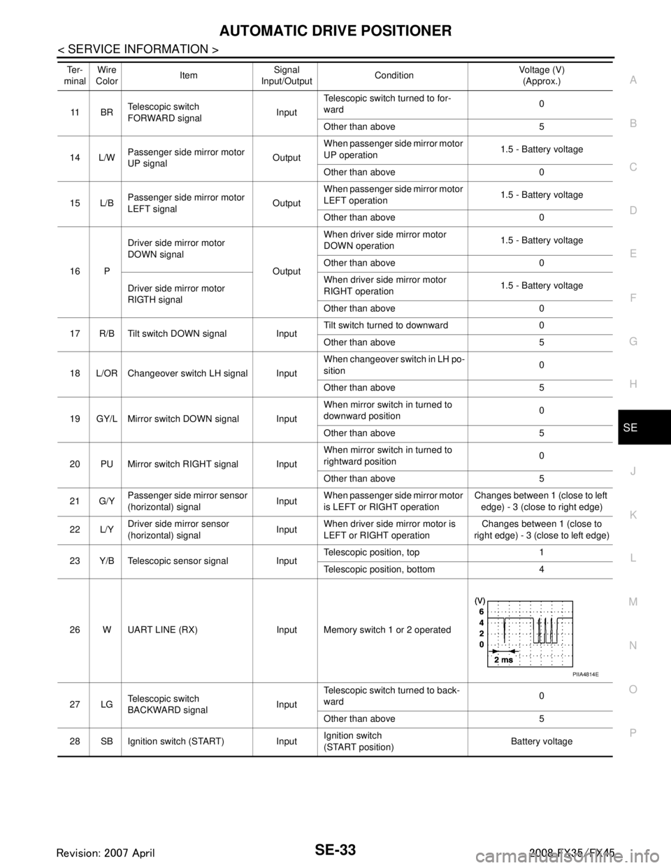
AUTOMATIC DRIVE POSITIONERSE-33
< SERVICE INFORMATION >
C
DE
F
G H
J
K L
M A
B
SE
N
O P
11 B R Telescopic switch
FORWARD signal
InputTelescopic switch turned to for-
ward
0
Other than above 5
14 L/W Passenger side
mirror motor
UP signal OutputWhen passenger si
de mirror motor
UP operation 1.5 - Battery voltage
Other than above 0
15 L/B Passenger side
mirror motor
LEFT signal OutputWhen passenger si
de mirror motor
LEFT operation 1.5 - Battery voltage
Other than above 0
16 P Driver side mirror motor
DOWN signal
OutputWhen driver side mirror motor
DOWN operation
1.5 - Battery voltage
Other than above 0
Driver side mirror motor
RIGTH signal When driver side mirror motor
RIGHT operation
1.5 - Battery voltage
Other than above 0
17 R/B Tilt switch DOWN signal Input Tilt switch turned to downward 0
Other than above 5
18 L/OR Changeover switch LH signal Input When changeover switch in LH po-
sition
0
Other than above 5
19 GY/L Mirror switch DOWN signal Input When mirror switch
in turned to
downward position 0
Other than above 5
20 PU Mirror switch RIGHT signal Input When mirror switch
in turned to
rightward position 0
Other than above 5
21 G/Y Passenger side
mirror sensor
(horizontal) signal InputWhen passenger si
de mirror motor
is LEFT or RIGHT operation Changes between 1 (close to left
edge) - 3 (close to right edge)
22 L/Y Driver side mirror sensor
(horizontal) signal
InputWhen driver side
mirror motor is
LEFT or RIGHT operation Changes between 1 (close to
right edge) - 3 (close to left edge)
23 Y/B Telescopic sensor signal Input Telescopic position, top 1
Telescopic position, bottom 4
26 W UART LINE (RX) Input Memory switch 1 or 2 operated
27 LG Telescopic switch
BACKWARD signal InputTelescopic switch turned to back-
ward
0
Other than above 5
28 SB Ignition switch (START) Input Ignition switch
(START position)
Battery voltage
Te r -
minal Wire
Color
Item Signal
Input/Output Condition Voltage (V)
(Approx.)
PIIA4814E
3AA93ABC3ACD3AC03ACA3AC03AC63AC53A913A773A893A873A873A8E3A773A983AC73AC93AC03AC3
3A893A873A873A8F3A773A9D3AAF3A8A3A8C3A863A9D3AAF3A8B3A8C
Page 3673 of 3924
SE-34
< SERVICE INFORMATION >
AUTOMATIC DRIVE POSITIONER
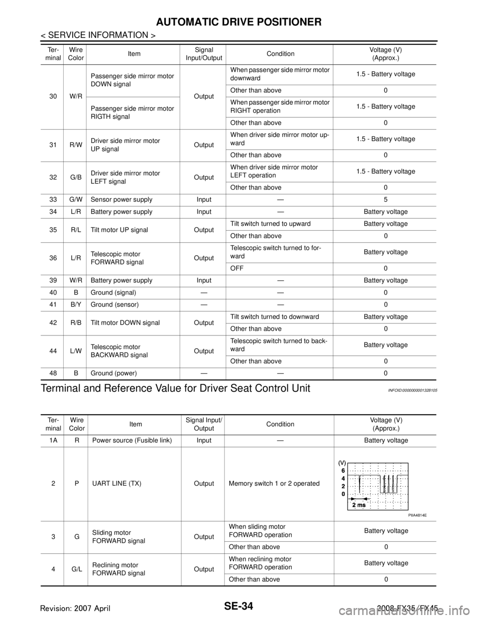
Terminal and Reference Value for Driver Seat Control Unit
INFOID:0000000001328105
30 W/RPassenger side
mirror motor
DOWN signal
OutputWhen passenger si
de mirror motor
downward 1.5 - Battery voltage
Other than above 0
Passenger side mirror motor
RIGTH signal When passenger si
de mirror motor
RIGHT operation 1.5 - Battery voltage
Other than above 0
31 R/W Driver side mirror motor
UP signal OutputWhen driver side mirror motor up-
ward
1.5 - Battery voltage
Other than above 0
32 G/B Driver side mirror motor
LEFT signal
OutputWhen driver side mirror motor
LEFT operation
1.5 - Battery voltage
Other than above 0
33 G/W Sensor power supply Input — 5
34 L/R Battery power supply Input — Battery voltage
35 R/L Tilt motor UP signal Output Tilt switch turned to upward Battery voltage
Other than above 0
36 L/R Telescopic motor
FORWARD signal OutputTelescopic switch turned to for-
ward
Battery voltage
OFF 0
39 W/R Battery power supply Input — Battery voltage
40 B Ground (signal) — — 0
41 B/Y Ground (sensor) — — 0
42 R/B Tilt motor DOWN signal Output Tilt switch turned to downward Battery voltage
Other than above 0
44 L/W Telescopic motor
BACKWARD signal OutputTelescopic switch turned to back-
ward
Battery voltage
Other than above 0
48 B Ground (power) — — 0
Te r -
minal Wire
Color Item Signal
Input/Output Condition Voltage (V)
(Approx.)
Te r -
minal Wire
Color ItemSignal Input/
Output Condition Voltage (V)
(Approx.)
1A R Power source (Fusible link) Input — Battery voltage
2 P UART LINE (TX) Output Memory switch 1 or 2 operated
3G Sliding motor
FORWARD signal OutputWhen sliding motor
FORWARD operation
Battery voltage
Other than above 0
4G/L Reclining motor
FORWARD signal OutputWhen reclining motor
FORWARD operation
Battery voltage
Other than above 0
PIIA4814E
3AA93ABC3ACD3AC03ACA3AC03AC63AC53A913A773A893A873A873A8E3A773A983AC73AC93AC03AC3
3A893A873A873A8F3A773A9D3AAF3A8A3A8C3A863A9D3AAF3A8B3A8C
Page 3674 of 3924
AUTOMATIC DRIVE POSITIONERSE-35
< SERVICE INFORMATION >
C
DE
F
G H
J
K L
M A
B
SE
N
O P
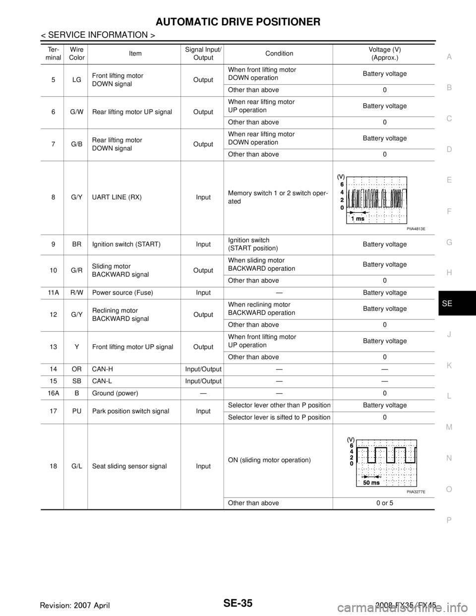
5LG Front lifting motor
DOWN signal
OutputWhen front lifting motor
DOWN operation
Battery voltage
Other than above 0
6 G/W Rear lifting motor UP signal Output When rear lifting motor
UP operation
Battery voltage
Other than above 0
7G/B Rear lifting motor
DOWN signal OutputWhen rear lifting motor
DOWN operation
Battery voltage
Other than above 0
8 G/Y UART LINE (RX) Input Memory switch 1 or 2 switch oper-
ated
9 BR Ignition switch (START) Input Ignition switch
(START position)Battery voltage
10 G/R Sliding motor
BACKWARD signal
OutputWhen sliding motor
BACKWARD operation
Battery voltage
Other than above 0
11A R/W Power source (Fuse) Input — Battery voltage
12 G/Y Reclining motor
BACKWARD signal OutputWhen reclining motor
BACKWARD operation
Battery voltage
Other than above 0
13 Y Front lifting motor UP signal Output When front lifting motor
UP operation
Battery voltage
Other than above 0
14 OR CAN-H Input/Output — —
15 SB CAN-L Input/Output — —
16A B Ground (power) — — 0
17 PU Park position switch signal Input Selector lever other than P position Battery voltage
Selector lever is sifted to P position 0
18 G/L Seat sliding sensor signal Input ON (sliding motor operation)
Other than above 0 or 5
Te r -
minal Wire
Color ItemSignal Input/
Output Condition Voltage (V)
(Approx.)
PIIA4813E
PIIA3277E
3AA93ABC3ACD3AC03ACA3AC03AC63AC53A913A773A893A873A873A8E3A773A983AC73AC93AC03AC3
3A893A873A873A8F3A773A9D3AAF3A8A3A8C3A863A9D3AAF3A8B3A8C
Page 3675 of 3924
SE-36
< SERVICE INFORMATION >
AUTOMATIC DRIVE POSITIONER
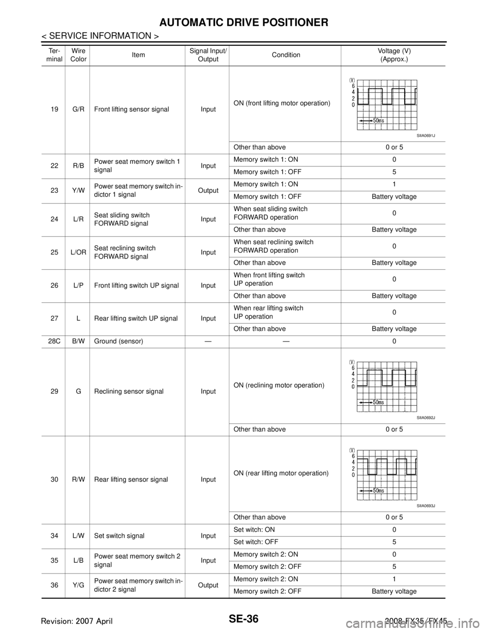
19 G/R Front lifting sensor signal InputON (front lifting motor operation)
Other than above 0 or 5
22 R/B Power seat memory switch 1
signal
InputMemory switch 1: ON 0
Memory switch 1: OFF 5
23 Y/W Power seat memory switch in-
dictor 1 signal
OutputMemory switch 1: ON 1
Memory switch 1: OFF Battery voltage
24 L/R Seat sliding switch
FORWARD signal InputWhen seat sliding switch
FORWARD operation
0
Other than above Battery voltage
25 L/OR Seat reclining switch
FORWARD signal
InputWhen seat reclining switch
FORWARD operation
0
Other than above Battery voltage
26 L/P Front lifting switch UP signal Input When front lifting switch
UP operation
0
Other than above Battery voltage
27 L Rear lifting switch UP signal Input When rear lifting switch
UP operation
0
Other than above Battery voltage
28C B/W Ground (sensor) — — 0
29 G Reclining sensor signal Input ON (reclining motor operation)
Other than above 0 or 5
30 R/W Rear lifting sensor signal Input ON (rear lifting motor operation)
Other than above 0 or 5
34 L/W Set switch signal Input Set witch: ON 0
Set witch: OFF 5
35 L/B Power seat memory switch 2
signal InputMemory switch 2: ON 0
Memory switch 2: OFF 5
36 Y/G Power seat memory switch in-
dictor 2 signal OutputMemory switch 2: ON 1
Memory switch 2: OFF Battery voltage
Te r -
minal Wire
Color ItemSignal Input/
Output Condition Voltage (V)
(Approx.)
SIIA0691J
SIIA0692J
SIIA0693J
3AA93ABC3ACD3AC03ACA3AC03AC63AC53A913A773A893A873A873A8E3A773A983AC73AC93AC03AC3
3A893A873A873A8F3A773A9D3AAF3A8A3A8C3A863A9D3AAF3A8B3A8C
Page 3676 of 3924
AUTOMATIC DRIVE POSITIONERSE-37
< SERVICE INFORMATION >
C
DE
F
G H
J
K L
M A
B
SE
N
O P
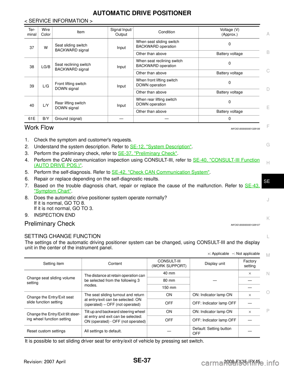
Work FlowINFOID:0000000001328106
1. Check the symptom and customer's requests.
2. Understand the system description. Refer to SE-12, "
System Description".
3. Perform the preliminary check, refer to SE-37, "
Preliminary Check".
4. Perform the CAN communication inspec tion using CONSULT-III, refer to SE-40, "
CONSULT-III Function
(AUTO DRIVE POS.)".
5. Perform the self-diagnosis. Refer to SE-42, "
Check CAN Communication System".
6. Repair or replace depending on the self-diagnostic results.
7. Based on the trouble diagnosis chart, repair or replace the cause of the malfunction. Refer to SE-43,
"Symptom Chart".
8. Does the automatic drive pos itioner system operate normally?
If it is normal, GO TO 8.
If it is not normal, GO TO 3.
9. INSPECTION END
Preliminary CheckINFOID:0000000001328107
SETTING CHANGE FUNCTION
The settings of the automatic driving positioner system can be changed, using CONSULT-III and the display
unit in the center of the instrument panel.
× : Applicable –: Not applicable
It is possible to set sliding driver seat fo r entry/exit of vehicle by pressing set switch.
37 WSeat sliding switch
BACKWARD signal
InputWhen seat sliding switch
BACKWARD operation
0
Other than above Battery voltage
38 LG/B Seat reclining switch
BACKWARD signal InputWhen seat reclining switch
BACKWARD operation
0
Other than above Battery voltage
39 L/G Front lifting switch
DOWN signal InputWhen front lifting switch
DOWN operation
0
Other than above Battery voltage
40 L/Y Rear lifting switch
DOWN signal
InputWhen rear lifting switch
DOWN operation
0
Other than above Battery voltage
61E B/Y Ground (signal) — — 0 Te r -
minal Wire
Color ItemSignal Input/
Output Condition Voltage (V)
(Approx.)
Setting item Content CONSULT-III
(WORK SUPPORT) Display unitFactory
setting
Change seat sliding volume
setting The distance at retain operation can
be selected from the following 3
modes. 40 mm
—×
80 mm —
150 mm —
Change the Entry/Exit seat
slide function setting The seat sliding turnout and return
at entry/exit can be selected: ON
(operated) – OFF (not operated) ON ON: Indicator lamp ON
×
OFF OFF: Indicator lamp OFF —
Change the Entry/Exit tilt steer-
ing wheel function setting Tilt up and backward steering wheel
at entry and exit can be selected:
ON (operated) - OFF (not operated) ON ON: Indicator lamp ON
×
OFF OFF: Indicator lamp OFF —
Reset custom settings All settings to default. — Default: Setting button
OFF
—
3AA93ABC3ACD3AC03ACA3AC03AC63AC53A913A773A893A873A873A8E3A773A983AC73AC93AC03AC3
3A893A873A873A8F3A773A9D3AAF3A8A3A8C3A863A9D3AAF3A8B3A8C
Page 3677 of 3924
SE-38
< SERVICE INFORMATION >
AUTOMATIC DRIVE POSITIONER
NOTE:
After the setting is registered, the new setting is effective, even if the battery is disconnected.
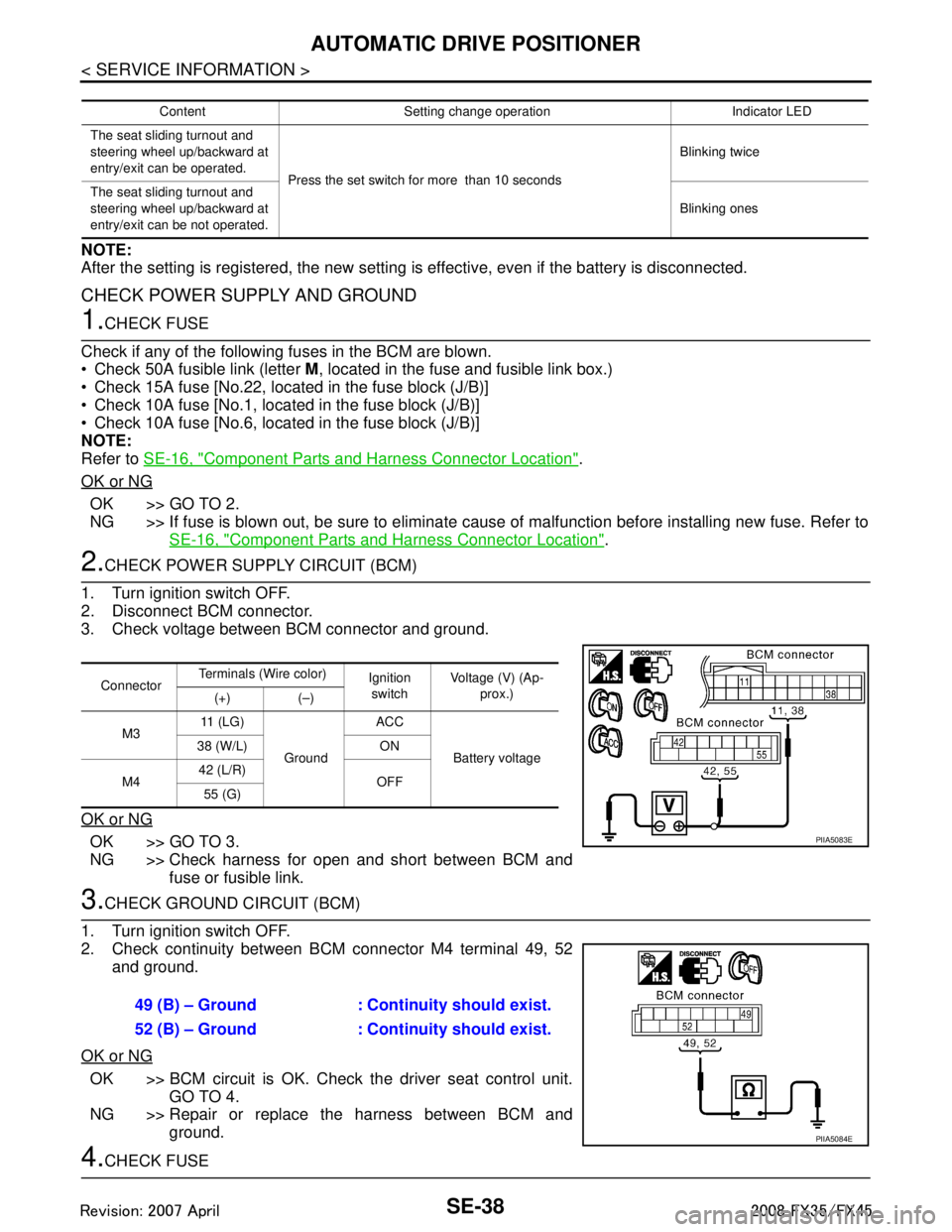
CHECK POWER SUPPLY AND GROUND
1.CHECK FUSE
Check if any of the following fuses in the BCM are blown.
Check 50A fusible link (letter M, located in the fuse and fusible link box.)
Check 15A fuse [No.22, located in the fuse block (J/B)]
Check 10A fuse [No.1, located in the fuse block (J/B)]
Check 10A fuse [No.6, located in the fuse block (J/B)]
NOTE:
Refer to SE-16, "
Component Parts and Harness Connector Location".
OK or NG
OK >> GO TO 2.
NG >> If fuse is blown out, be sure to eliminate cause of malfunction before installing new fuse. Refer to SE-16, "
Component Parts and Harness Connector Location".
2.CHECK POWER SUPPLY CIRCUIT (BCM)
1. Turn ignition switch OFF.
2. Disconnect BCM connector.
3. Check voltage between BCM connector and ground.
OK or NG
OK >> GO TO 3.
NG >> Check harness for open and short between BCM and fuse or fusible link.
3.CHECK GROUND CIRCUIT (BCM)
1. Turn ignition switch OFF.
2. Check continuity between BCM connector M4 terminal 49, 52 and ground.
OK or NG
OK >> BCM circuit is OK. Check the driver seat control unit. GO TO 4.
NG >> Repair or replace the harness between BCM and ground.
4.CHECK FUSE
Content Setting change operation Indicator LED
The seat sliding turnout and
steering wheel up/backward at
entry/exit can be operated. Press the set switch for more than 10 seconds Blinking twice
The seat sliding turnout and
steering wheel up/backward at
entry/exit can be not operated. Blinking ones
Connector
Terminals (Wire color)
Ignition
switch Voltage (V) (Ap-
prox.)
(+) (–)
M3 11 ( L G )
Ground ACC
Battery voltage
38 (W/L) ON
M4 42 (L/R)
OFF
55 (G)
PIIA5083E
49 (B) – Ground : Continuity should exist.
52 (B) – Ground : Continuity should exist.
PIIA5084E
3AA93ABC3ACD3AC03ACA3AC03AC63AC53A913A773A893A873A873A8E3A773A983AC73AC93AC03AC3
3A893A873A873A8F3A773A9D3AAF3A8A3A8C3A863A9D3AAF3A8B3A8C
Page 3678 of 3924
![INFINITI FX35 2008 Service Manual
AUTOMATIC DRIVE POSITIONERSE-39
< SERVICE INFORMATION >
C
DE
F
G H
J
K L
M A
B
SE
N
O P
Check 10A fuse [No.9, loca ted in fuse block (J/B)].
NOTE:
Refer to SE-16, "
Component Parts and Harness Con INFINITI FX35 2008 Service Manual
AUTOMATIC DRIVE POSITIONERSE-39
< SERVICE INFORMATION >
C
DE
F
G H
J
K L
M A
B
SE
N
O P
Check 10A fuse [No.9, loca ted in fuse block (J/B)].
NOTE:
Refer to SE-16, "
Component Parts and Harness Con](/manual-img/42/57017/w960_57017-3677.png)
AUTOMATIC DRIVE POSITIONERSE-39
< SERVICE INFORMATION >
C
DE
F
G H
J
K L
M A
B
SE
N
O P
Check 10A fuse [No.9, loca ted in fuse block (J/B)].
NOTE:
Refer to SE-16, "
Component Parts and Harness Connector Location".
OK or NG
OK >> GO TO 5.
NG >> If fuse is blown out, be sure to eliminate c ause of malfunction before installing new fuse. Refer to
SE-16, "
Component Parts and Harness Connector Location".
5.CHECK POWER SUPPLY CIRCUIT (DRIVER SEAT CONTROL UNIT)
1. Disconnect driver seat control unit connector.
2. Check voltage between driver seat control unit and ground.
OK or NG
OK >> GO TO 6.
NG >> Repair or replace harness between driver seat control unit and fuse block (J/B).
6.CHECK GROUND CIRCUIT (DRIVER SEAT CONTROL UNIT)
1. Turn ignition switch OFF.
2. Check continuity between the dr iver seat control unit connector
B152, B153 terminal16A, 61E and ground.
OK or NG
OK >> GO TO 7.
NG >> Repair or replace harness between driver seat control unit and ground.
7.CHECK POWER SUPPLY CIRCUIT (AUTOMAT IC DRIVE POSITIONER CONTROL UNIT)
1. Disconnect automatic drive positioner control unit connector.
2. Check voltage between automatic drive positioner control unit and ground.
OK or NG
OK >> GO TO 8.
NG >> Repair or replace harness between automatic drive positioner control unit and fuse block (J/B).
8.CHECK GROUND CIRCUIT (AUTOMATIC DRI VE POSITIONER CONTROL UNIT)
ConnectorTerminals (W
ire color)
Ignition
switch Voltage (V)
(Approx.)
(+) (–)
B152 9 (BR) GroundSTART
Battery voltage
B153 1A (R)
OFF
11 A ( R / W )
PIIA5085E
16A (B) – Ground : Continuity should exist.
61E (B/Y) – Ground : Continuity should exist.
PIIA5087E
Connector Terminals (W
ire color)
Ignition
switch Voltage (V)
(Approx.)
(+) (–)
M49 28 (SB) GroundSTART
Battery voltage
M50 34 (L/R)
OFF
39 (W/R)
PIIA5086E
3AA93ABC3ACD3AC03ACA3AC03AC63AC53A913A773A893A873A873A8E3A773A983AC73AC93AC03AC3
3A893A873A873A8F3A773A9D3AAF3A8A3A8C3A863A9D3AAF3A8B3A8C