Page 3614 of 3924

BATTERYSC-5
< SERVICE INFORMATION >
C
DE
F
G H
I
J
L
M A
B
SC
N
O P
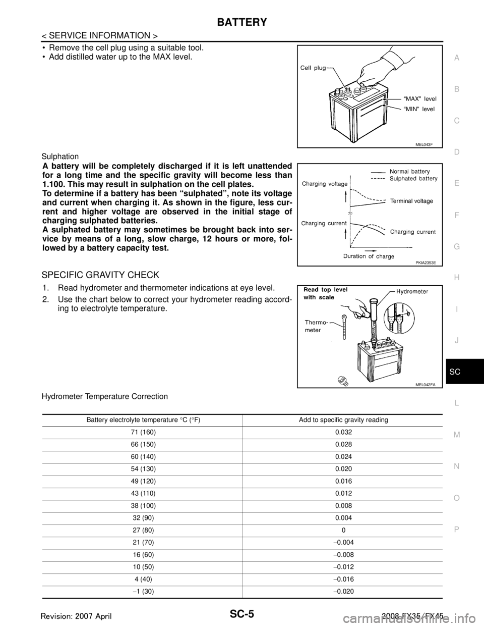
Remove the cell plug using a suitable tool.
Add distilled water up to the MAX level.
Sulphation
A battery will be completely discharged if it is left unattended
for a long time and the specific gravity will become less than
1.100. This may result in su lphation on the cell plates.
To determine if a battery has been “sulphated”, note its voltage
and current when charging it. As shown in the figure, less cur-
rent and higher voltage are observed in the initial stage of
charging sulphated batteries.
A sulphated battery may sometimes be brought back into ser-
vice by means of a long, slow charge, 12 hours or more, fol-
lowed by a battery capacity test.
SPECIFIC GRAVITY CHECK
1. Read hydrometer and thermometer indications at eye level.
2. Use the chart below to correct your hydrometer reading accord- ing to electrolyte temperature.
Hydrometer Temperature Correction
MEL043F
PKIA2353E
MEL042FA
Battery electrolyte temperature °C ( °F) Add to specific gravity reading
71 (160) 0.032
66 (150) 0.028
60 (140) 0.024
54 (130) 0.020
49 (120) 0.016 43 (110) 0.012
38 (100) 0.008
32 (90) 0.004
27 (80) 0
21 (70) −0.004
16 (60) −0.008
10 (50) −0.012
4 (40) −0.016
− 1 (30) −0.020
3AA93ABC3ACD3AC03ACA3AC03AC63AC53A913A773A893A873A873A8E3A773A983AC73AC93AC03AC3
3A893A873A873A8F3A773A9D3AAF3A8A3A8C3A863A9D3AAF3A8B3A8C
Page 3615 of 3924

SC-6
< SERVICE INFORMATION >
BATTERY
CHARGING THE BATTERY
CAUTION:
Never “quick charge” a fully discharged battery.
Keep the battery away from open flame while it is being charged.
When connecting the charger, connect the leads first, then turn on the charger. Never turn on the
charger first, as this may cause a spark.
If battery electrolyte temperature rises above 55 °C (131 °F), stop charging. Always charge battery at a
temperature below 55 °C (131 °F).
Charging Rates
Never charge at more than 50 ampere rate.
NOTE:
The ammeter reading on your battery charger will automat ically decrease as the battery charges. This indi-
cates that the voltage of the battery is increasing norma lly as the state of charge improves. The charging amps
indicated above refer to initial charge rate.
If, after charging, the specific gravity of any two ce lls varies more than 0.050, the battery should be replaced.
Trouble Diagnosis with Battery Service CenterINFOID:0000000001328244
For battery testing, use Battery Service Center (J-48087) . For details and operating instructions, refer to Tech-
nical Service Bulletin and/or Battery Service Center User Guide.
Removal and InstallationINFOID:0000000001328245
REMOVAL
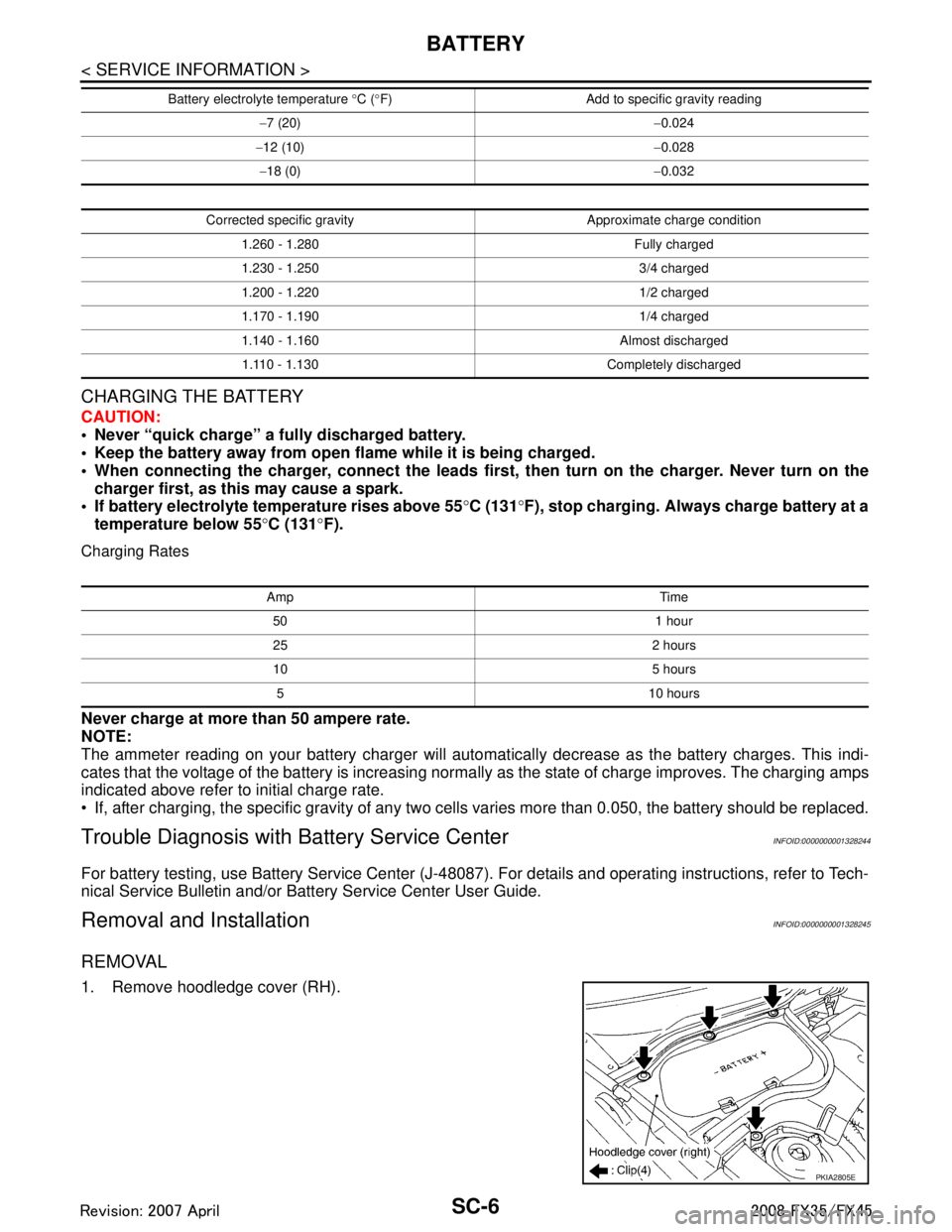
1. Remove hoodledge cover (RH).
− 7 (20) −0.024
− 12 (10) −0.028
− 18 (0) −0.032
Corrected specific gravity Approximate charge condition 1.260 - 1.280 Fully charged
1.230 - 1.250 3/4 charged
1.200 - 1.220 1/2 charged
1.170 - 1.190 1/4 charged
1.140 - 1.160 Almost discharged1.110 - 1.130 Completely discharged
Battery electrolyte temperature
°C ( °F) Add to specific gravity reading
Amp Time
50 1 hour
25 2 hours
10 5 hours5 10 hours
PKIA2805E
3AA93ABC3ACD3AC03ACA3AC03AC63AC53A913A773A893A873A873A8E3A773A983AC73AC93AC03AC3
3A893A873A873A8F3A773A9D3AAF3A8A3A8C3A863A9D3AAF3A8B3A8C
Page 3616 of 3924
BATTERYSC-7
< SERVICE INFORMATION >
C
DE
F
G H
I
J
L
M A
B
SC
N
O P
2. Remove cowl top cover (RH). Refer to EI-23, "Removal and Installation"
3. Disconnect both battery c ables from terminals.
CAUTION:
When disconnecting, disconnect the battery cable from the
negative terminal first.
4. Remove battery fix frame mounting nuts and battery fix frame.
5. Remove battery.
INSTALLATION
Installation is the reverse order of removal.
CAUTION:
When connecting, connect the battery cable to the positive terminal first.
PKIA2806E
Battery fix frame mounting nut
: 3.9 N·m (0.4 kg-m, 35 in-lb)
Battery terminal nut
: 5.4 N·m (0.55 kg-m, 48 in-lb)
3AA93ABC3ACD3AC03ACA3AC03AC63AC53A913A773A893A873A873A8E3A773A983AC73AC93AC03AC3
3A893A873A873A8F3A773A9D3AAF3A8A3A8C3A863A9D3AAF3A8B3A8C
Page 3617 of 3924

SC-8
< SERVICE INFORMATION >
STARTING SYSTEM
STARTING SYSTEM
System DescriptionINFOID:0000000001328246
Power is supplied at all times
through 40A fusible link (letter F, located in the fuse and fusible link block)
to ignition switch terminal 1,
through 15A fuse (No. 78, located in the IPDM E/R)
to CPU of IPDM E/R,
through 10A fuse (No. 71, located in the IPDM E/R)
to CPU of IPDM E/R.
When the selector lever in the P or N position, power is supplied
from TCM, and through A/T assembly terminal 9
to IPDM E/R terminal 53.
Ground is supplied
to IPDM E/R terminals 38, 50 and 60
from grounds E21, E50 and E51.
With the ignition switch in the START position, and provided that the IPDM E/R receives a starter relay ON sig-
nal from the CAN lines, the IPDM E/ R is energized and power is supplied
from ignition switch terminal 5
to IPDM E/R terminal 4 and
through IPDM E/R terminal 3
to starter motor terminal 1.
The starter motor plunger closes and provides a clos ed circuit between the battery and starter motor. The
starter motor is grounded to the engine block. With power and ground supplied, cranking occurs and the
engine starts.
3AA93ABC3ACD3AC03ACA3AC03AC63AC53A913A773A893A873A873A8E3A773A983AC73AC93AC03AC3
3A893A873A873A8F3A773A9D3AAF3A8A3A8C3A863A9D3AAF3A8B3A8C
Page 3618 of 3924
STARTING SYSTEMSC-9
< SERVICE INFORMATION >
C
DE
F
G H
I
J
L
M A
B
SC
N
O P
Wiring Diagram - START -INFOID:0000000001328247
VK45DE ENGINE MODELS
TKWM1275E
3AA93ABC3ACD3AC03ACA3AC03AC63AC53A913A773A893A873A873A8E3A773A983AC73AC93AC03AC3
3A893A873A873A8F3A773A9D3AAF3A8A3A8C3A863A9D3AAF3A8B3A8C
Page 3619 of 3924
SC-10
< SERVICE INFORMATION >
STARTING SYSTEM
VQ35DE ENGINE MODELS
Trouble Diagnosis with Starting/Charging System Tester (Starting)INFOID:0000000001328248
For starting system testing, use Starting/Charging Syst em Tester (J-44373). For details and operating instruc-
tions, refer to Technical Service Bulletin.
TKWM1276E
3AA93ABC3ACD3AC03ACA3AC03AC63AC53A913A773A893A873A873A8E3A773A983AC73AC93AC03AC3
3A893A873A873A8F3A773A9D3AAF3A8A3A8C3A863A9D3AAF3A8B3A8C
Page 3620 of 3924
STARTING SYSTEMSC-11
< SERVICE INFORMATION >
C
DE
F
G H
I
J
L
M A
B
SC
N
O P
DIAGNOSTIC PROCEDURE 1
Check “B” Terminal Circuit
CAUTION:
Perform diagnosis under the cond ition that engine cannot start by the following procedure.
*1 For battery testing, use Battery Ser-
vice Center (J-480 87). For details
and operating instructions, refer to
Technical Service Bulletin and/or Bat-
tery Service Center User Guide. *2 Refer to "MINIMUM SPECIFICA-
TION OF CRANKING VOLTAGE
REFERENCING COOLANT TEM-
PERATURE". *3 Refer to "Check “B” Terminal Circuit".
*4 Refer to "Check “S” Connector Cir-
cuit".
SKIB1369E
3AA93ABC3ACD3AC03ACA3AC03AC63AC53A913A773A893A873A873A8E3A773A983AC73AC93AC03AC3
3A893A873A873A8F3A773A9D3AAF3A8A3A8C3A863A9D3AAF3A8B3A8C
Page 3621 of 3924

SC-12
< SERVICE INFORMATION >
STARTING SYSTEM
1. Remove fuel pump fuse.
2. Crank or start the engine (where possible) until the fuel pressure is released.
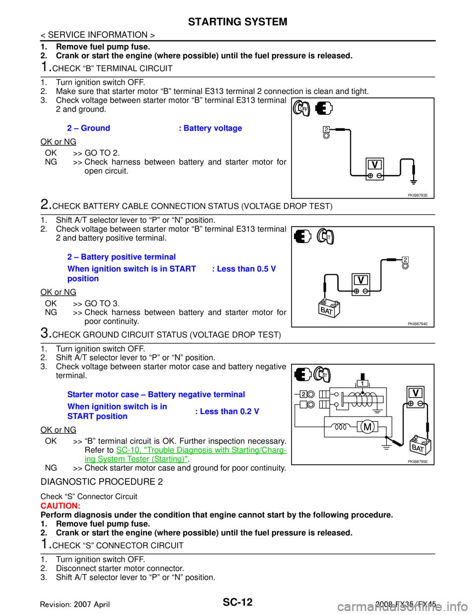
1.CHECK “B” TERMINAL CIRCUIT
1. Turn ignition switch OFF.
2. Make sure that starter motor “B” terminal E313 terminal 2 connection is clean and tight.
3. Check voltage between starter motor “B” terminal E313 terminal 2 and ground.
OK or NG
OK >> GO TO 2.
NG >> Check harness between battery and starter motor for open circuit.
2.CHECK BATTERY CABLE CONNECTION STATUS (VOLTAGE DROP TEST)
1. Shift A/T selector lever to “P” or “N” position.
2. Check voltage between starter motor “B” terminal E313 terminal 2 and battery positive terminal.
OK or NG
OK >> GO TO 3.
NG >> Check harness between battery and starter motor for poor continuity.
3.CHECK GROUND CIRCUIT STATUS (VOLTAGE DROP TEST)
1. Turn ignition switch OFF.
2. Shift A/T selector lever to “P” or “N” position.
3. Check voltage between starter motor case and battery negative terminal.
OK or NG
OK >> “B” terminal circuit is OK. Further inspection necessary. Refer to SC-10, "
Trouble Diagnosis with Starting/Charg-
ing System Tester (Starting)".
NG >> Check starter motor case and ground for poor continuity.
DIAGNOSTIC PROCEDURE 2
Check “S” Connector Circuit
CAUTION:
Perform diagnosis under the condi tion that engine cannot start by the following procedure.
1. Remove fuel pump fuse.
2. Crank or start the engine (where possi ble) until the fuel pressure is released.
1.CHECK “S” CONNECTOR CIRCUIT
1. Turn ignition switch OFF.
2. Disconnect starter motor connector.
3. Shift A/T selector lever to “P” or “N” position. 2 – Ground : Battery voltage
PKIB8793E
2 – Battery positive terminal
When ignition switch is in START
position
: Less than 0.5 V
PKIB8794E
Starter motor case – Battery negative terminal
When ignition switch is in
START position
: Less than 0.2 V
PKIB8795E
3AA93ABC3ACD3AC03ACA3AC03AC63AC53A913A773A893A873A873A8E3A773A983AC73AC93AC03AC3
3A893A873A873A8F3A773A9D3AAF3A8A3A8C3A863A9D3AAF3A8B3A8C