Page 3590 of 3924
SHOCK ABSORBERRSU-9
< SERVICE INFORMATION >
C
DF
G H
I
J
K L
M A
B
RSU
N
O P
SHOCK ABSORBER
Removal and InstallationINFOID:0000000001327555
REMOVAL
1. Remove tires from vehicle with power tool.
2. Set jack under rear lower link.
3. Remove fixing bolt in lower side of shock absorber assembly with power tool.
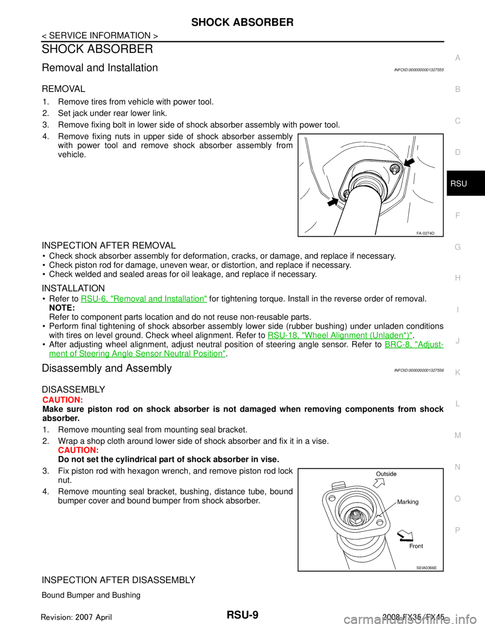
4. Remove fixing nuts in upper side of shock absorber assembly with power tool and remove shock absorber assembly from
vehicle.
INSPECTION AFTER REMOVAL
Check shock absorber assembly for deformation, cracks, or damage, and replace if necessary.
Check piston rod for damage, uneven wear, or distortion, and replace if necessary.
Check welded and sealed areas for oil leakage, and replace if necessary.
INSTALLATION
Refer to RSU-6, "Removal and Installation" for tightening torque. Install in the reverse order of removal.
NOTE:
Refer to component parts location and do not reuse non-reusable parts.
Perform final tightening of shock absorber assembly lower side (rubber b\
ushing) under unladen conditions
with tires on level ground. Check wheel alignment. Refer to RSU-18, "
Wheel Alignment (Unladen*)".
After adjusting wheel alignment, adjust neutral position of steering angle sensor. Refer to BRC-8, "
Adjust-
ment of Steering Angle Sensor Neutral Position".
Disassembly and AssemblyINFOID:0000000001327556
DISASSEMBLY
CAUTION:
Make sure piston rod on shock absorber is not damaged when removing components from shock
absorber.
1. Remove mounting seal fr om mounting seal bracket.
2. Wrap a shop cloth around lower side of shock absorber and fix it in a vise. CAUTION:
Do not set the cylindrical part of shock absorber in vise.
3. Fix piston rod with hexagon wrench, and remove piston rod lock nut.
4. Remove mounting seal bracke t, bushing, distance tube, bound
bumper cover and bound bumper from shock absorber.
INSPECTION AFTER DISASSEMBLY
Bound Bumper and Bushing
FA-0274D
SEIA0366E
3AA93ABC3ACD3AC03ACA3AC03AC63AC53A913A773A893A873A873A8E3A773A983AC73AC93AC03AC3
3A893A873A873A8F3A773A9D3AAF3A8A3A8C3A863A9D3AAF3A8B3A8C
Page 3591 of 3924
RSU-10
< SERVICE INFORMATION >
SHOCK ABSORBER
Check bound bumper and bushing for cracks, deformation or other damage. Replace if necessary.
ASSEMBLY
Refer to RSU-6, "Removal and Installation" for tightening torque. Assembly in the reverse order of disas-
sembly.
NOTE:
Refer to component parts location and do not reuse non-reusable parts.
Make sure piston rod on shock absorber is not damaged when attaching components to shock absorber.
3AA93ABC3ACD3AC03ACA3AC03AC63AC53A913A773A893A873A873A8E3A773A983AC73AC93AC03AC3
3A893A873A873A8F3A773A9D3AAF3A8A3A8C3A863A9D3AAF3A8B3A8C
Page 3592 of 3924
SUSPENSION ARMRSU-11
< SERVICE INFORMATION >
C
DF
G H
I
J
K L
M A
B
RSU
N
O P
SUSPENSION ARM
Removal and InstallationINFOID:0000000001327557
REMOVAL
1. Remove tires from vehicle with power tool.
2. Remove stabilizer connecting rod mounting br acket from suspension arm with power tool.
3. Remove drive shaft from vehicle. (VK45DE models) Refer to RAX-10, "
Removal and Installation".
4. Remove cotter pin of suspension arm ball joint, and loosen nut.
5. Use a ball joint remover (suitable tool) to remove suspension arm from axle assembly. Be careful not to damage ball joint boot.
CAUTION:
Tighten temporarily mounting nu t to prevent damage to threads and to prevent ball joint remover
(suitable tool) from coming off.
6. Remove fixing nuts and bolts between suspension arm and rear suspension member with power tool.
7. Remove suspension arm from vehicle.
INSPECTION AFTER REMOVAL
Visual Inspection
Check suspension arm and bushing for deformation, cracks, or damage. If any non-standard condition is
found, replace it.
Check boot of ball joint for cracks, or damage, and also for grease leakage.
Ball Joint Inspection
Manually move ball stud to confirm it moves smoothly with no binding.
Swing Torque Inspection
NOTE:
Before measuring, move ball joint at least ten times by hand to check for smooth movement.
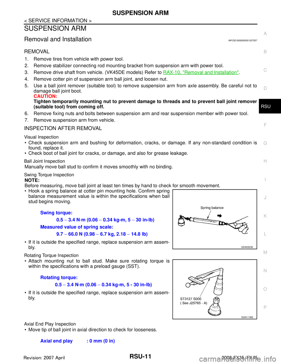
Hook a spring balance at cotter pin mounting hole. Confirm spring balance measurement value is withi n the specifications when ball
stud begins moving.
If it is outside the specified r ange, replace suspension arm assem-
bly.
Rotating Torque Inspection
Attach mounting nut to ball stud. Make sure rotating torque is within the specifications with a preload gauge (SST).
If it is outside the specified r ange, replace suspension arm assem-
bly.
Axial End Play Inspection
Move tip of ball joint in axial direction to check for looseness. Swing torque:
0.5
− 3.4 N·m (0.06 − 0.34 kg-m, 5 − 30 in-lb)
Measured value of spring scale:
9.7 − 66.0 N (0.98 − 6.7 kg, 2.18 − 14.8 lb)
SEIA0523E
Rotating torque:
0.5 − 3.4 N·m (0.06 − 0.34 kg-m, 5 - 30 in-lb)
SDIA1150E
Axial end play : 0 mm (0 in)
3AA93ABC3ACD3AC03ACA3AC03AC63AC53A913A773A893A873A873A8E3A773A983AC73AC93AC03AC3
3A893A873A873A8F3A773A9D3AAF3A8A3A8C3A863A9D3AAF3A8B3A8C
Page 3593 of 3924
RSU-12
< SERVICE INFORMATION >
SUSPENSION ARM
If it is outside the specified range, replace suspension arm assembly.
INSTALLATION
Refer to RSU-6, "Removal and Installation" for tightening torque. Install in the reverse order of removal.
NOTE:
Refer to component parts location and do not reuse non-reusable parts.
Perform final tightening of rear suspension member installation position (rubber bushing) under unladen
conditions with tires on level ground. Check wheel alignment. Refer to RSU-5, "
Wheel AlignmentInspection".
After adjusting wheel alignment, adjust neutral position of steering angle sensor. Refer to BRC-8, "
Adjust-
ment of Steering Angle Sensor Neutral Position".
3AA93ABC3ACD3AC03ACA3AC03AC63AC53A913A773A893A873A873A8E3A773A983AC73AC93AC03AC3
3A893A873A873A8F3A773A9D3AAF3A8A3A8C3A863A9D3AAF3A8B3A8C
Page 3594 of 3924
RADIUS RODRSU-13
< SERVICE INFORMATION >
C
DF
G H
I
J
K L
M A
B
RSU
N
O P
RADIUS ROD
Removal and InstallationINFOID:0000000001327558
REMOVAL
1. Remove tires from vehicle with power tool.
2. Set jack under rear lower link.
3. Remove fixing bolt and nut in axle side of radius rod.
4. Remove fixing bolt in rear suspension member side of radius rod with power tool, then remove radius rod
from vehicle.
INSPECTION AFTER REMOVAL
Check radius rod and bushing for any deformation, cracks, or damage. Replace if necessary.
INSTALLATION
Refer to RSU-6, "Removal and Installation" for tightening torque. Install in the reverse order of removal.
NOTE:
Refer to component parts location and do not reuse non-reusable parts.
Perform final tightening of rear suspension mem ber and axle installation position (rubber bushing) under
unladen conditions with tires on level ground. Check wheel alignment. Refer to RSU-5, "
Wheel AlignmentIn-
spection".
After adjusting wheel alignment, adjust neutral position of steering angle sensor. Refer to BRC-8, "
Adjust-
ment of Steering Angle Sensor Neutral Position".
3AA93ABC3ACD3AC03ACA3AC03AC63AC53A913A773A893A873A873A8E3A773A983AC73AC93AC03AC3
3A893A873A873A8F3A773A9D3AAF3A8A3A8C3A863A9D3AAF3A8B3A8C
Page 3595 of 3924
RSU-14
< SERVICE INFORMATION >
FRONT LOWER LINK
FRONT LOWER LINK
Removal and InstallationINFOID:0000000001327559
REMOVAL
1. Remove tires from vehicle with power tool.
2. Set jack under rear lower link.
3. Remove front lower link protector.
4. Remove shock absorber assembly from vehicle. Refer to RSU-9, "
Removal and Installation".
5. Remove fixing nut and bolt between front lower link and axle with power tool.
6. Remove fixing nut and bolt between front lower li nk and rear suspension member with power tool.
7. Remove front lower link from vehicle.
INSPECTION AFTER REMOVAL
Check front lower link and bushing for any deforma tion, crack, or damage. Replace if necessary.
INSTALLATION
Refer to RSU-6, "Removal and Installation" for tightening torque. Install in the reverse order of removal.
NOTE:
Refer to component parts location and do not reuse non-reusable parts.
Perform final tightening of rear suspension member and axle installation position (rubber bushing) under
unladen conditions with tires on level ground. Check wheel alignment. Refer to RSU-5, "
Wheel AlignmentIn-
spection".
After adjusting wheel alignment, adjust neutral position of steering angle sensor. Refer to BRC-8, "
Adjust-
ment of Steering Angle Sensor Neutral Position".
3AA93ABC3ACD3AC03ACA3AC03AC63AC53A913A773A893A873A873A8E3A773A983AC73AC93AC03AC3
3A893A873A873A8F3A773A9D3AAF3A8A3A8C3A863A9D3AAF3A8B3A8C
Page 3596 of 3924
REAR LOWER LINK & COIL SPRINGRSU-15
< SERVICE INFORMATION >
C
DF
G H
I
J
K L
M A
B
RSU
N
O P
REAR LOWER LINK & COIL SPRING
Removal and InstallationINFOID:0000000001327560
REMOVAL
1. Remove tire with power tool.
2. Set jack under rear lower link.
3. Loosen fixing bolt and nut between rear lower link and suspension member, and then remove fixing bolt and nut between rear axle and rear lower link with power tool.
4. Slowly lower jack, then remove upper seat, co il spring and rubber seat from rear lower link.
5. Remove fixing bolt and nut between rear suspensi on member and rear lower link with power tool.
INSPECTION AFTER REMOVAL
Check rear lower link, bushing and coil spring for deformation, cracks, and damage. Replace rear lower link
and coil spring if necessary.
INSTALLATION
Refer to RSU-6, "Removal and Installation"for tightening torque. Install in the reverse order of removal.
CAUTION:
Refer to component parts location an d do not reuse non-reusable parts.
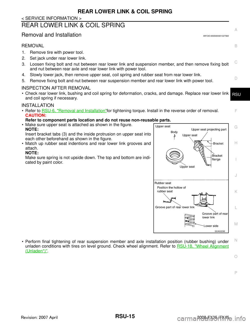
Make sure upper seat is attached as shown in the figure.
NOTE:
Insert bracket tabs (3) and the inside protrusion on upper seat into
each other beforehand as shown in the figure.
Match up rubber seat indentions and rear lower link grooves and
attach.
NOTE:
Make sure spring is not upside down. The top and bottom are indi-
cated by paint color.
Perform final tightening of rear suspension mem ber and axle installation position (rubber bushing) under
unladen conditions with tires on level ground. Check wheel alignment. Refer to RSU-18, "
Wheel Alignment
(Unladen*)".
SEIA0229E
3AA93ABC3ACD3AC03ACA3AC03AC63AC53A913A773A893A873A873A8E3A773A983AC73AC93AC03AC3
3A893A873A873A8F3A773A9D3AAF3A8A3A8C3A863A9D3AAF3A8B3A8C
Page 3597 of 3924
RSU-16
< SERVICE INFORMATION >
STABILIZER BAR
STABILIZER BAR
Removal and InstallationINFOID:0000000001327561
REMOVAL
1. Remove tires from vehicle with power tool.
2. Remove center muffler from vehicle. Refer to EX-3, "
Component".
3. Remove fixing bolts and remove stabilizer connecting rod mount bracket from suspension arm with power tool.
4. Remove lower side fixing nut on stabilizer connecting rod and remove stabilizer connecting rod from stabi- lizer bar with power tool.
5. Remove fixing nuts on stabilizer clamps and remove stabilizer from vehicle with power tool.
INSPECTION AFTER REMOVAL
Check stabilizer bar, stabilizer bushings, stabilizer clamps, stabilizer connecting rod, stabilizer connecting rod
mounting bracket for any deformation, cracks or damage. Replace if necessary.
INSTALLATION
Refer to RSU-6, "Removal and Installation" for tightening torque. Install in the reverse order of removal.
NOTE:
Refer to component parts location and do not reuse non-reusable parts.
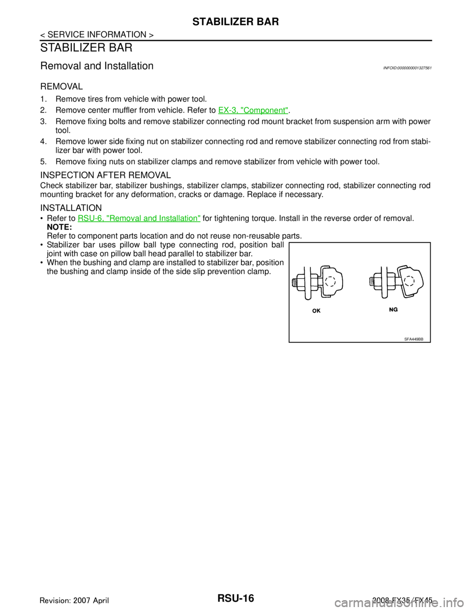
Stabilizer bar uses pillow ball type connecting rod, position ball joint with case on pillow ball head parallel to stabilizer bar.
When the bushing and clamp are installed to stabilizer bar, position
the bushing and clamp inside of t he side slip prevention clamp.
SFA449BB
3AA93ABC3ACD3AC03ACA3AC03AC63AC53A913A773A893A873A873A8E3A773A983AC73AC93AC03AC3
3A893A873A873A8F3A773A9D3AAF3A8A3A8C3A863A9D3AAF3A8B3A8C