2008 INFINITI FX35 ECO mode
[x] Cancel search: ECO modePage 3381 of 3924
IPDM E/R (INTELLIGENT POWER DISTRIBUTION MODULE ENGINE ROOM)
PG-17
< SERVICE INFORMATION >
C
D E
F
G H
I
J
L
M A
B
PG
N
O P
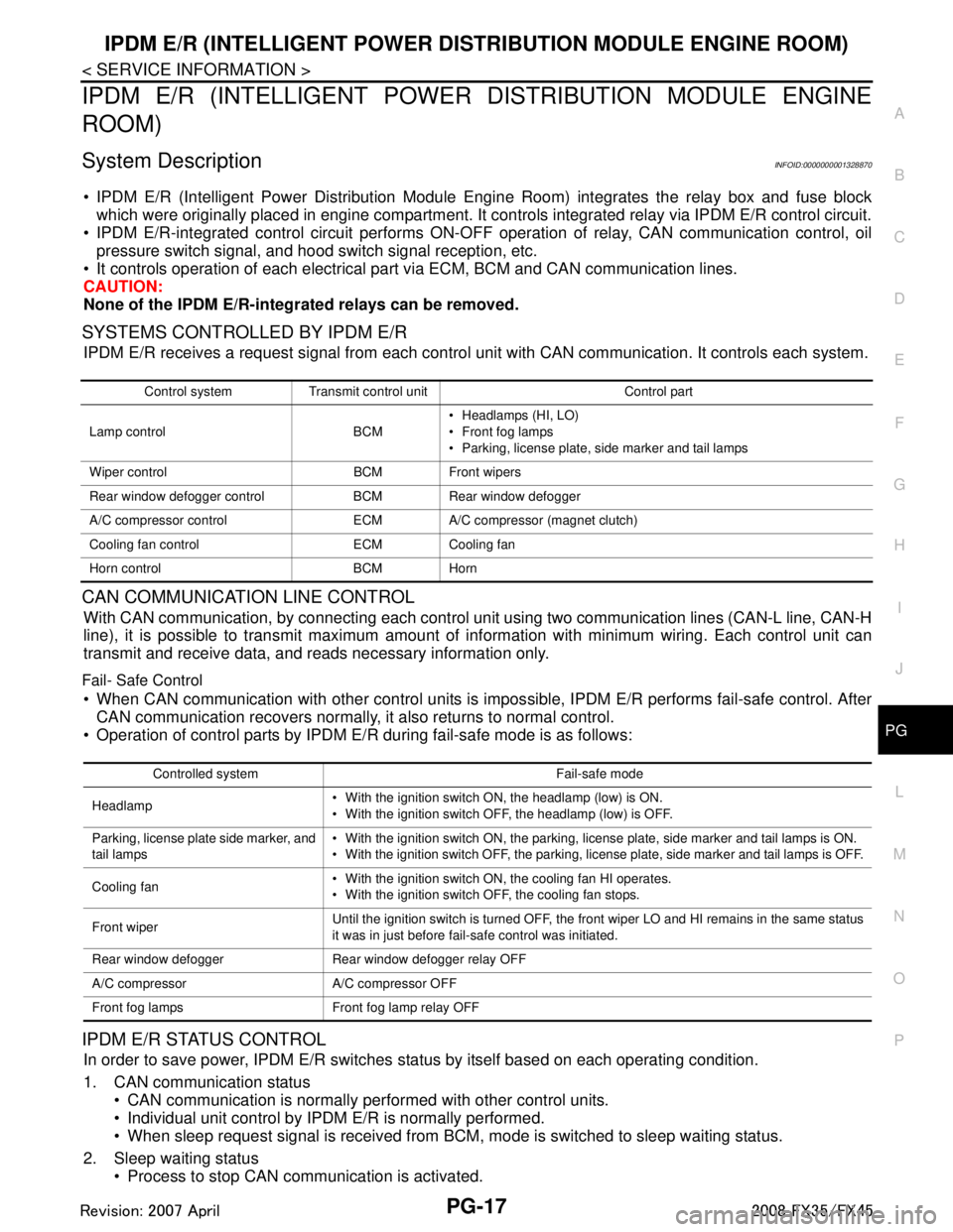
IPDM E/R (INTELLIGENT POWER DISTRIBUTION MODULE ENGINE
ROOM)
System DescriptionINFOID:0000000001328870
IPDM E/R (Intelligent Power Distribution Module Engi ne Room) integrates the relay box and fuse block
which were originally placed in engine compartment. It c ontrols integrated relay via IPDM E/R control circuit.
IPDM E/R-integrated control circuit performs ON-OFF operation of relay, CAN communication control, oil
pressure switch signal, and hood switch signal reception, etc.
It controls operation of each electrical pa rt via ECM, BCM and CAN communication lines.
CAUTION:
None of the IPDM E/R-integr ated relays can be removed.
SYSTEMS CONTROLLED BY IPDM E/R
IPDM E/R receives a request signal fr om each control unit with CAN communication. It controls each system.
CAN COMMUNICATION LINE CONTROL
With CAN communication, by connecting each control uni t using two communication lines (CAN-L line, CAN-H
line), it is possible to transmit maximum amount of in formation with minimum wiring. Each control unit can
transmit and receive data, and reads necessary information only.
Fail- Safe Control
When CAN communication with other control units is impos sible, IPDM E/R performs fail-safe control. After
CAN communication recovers normally, it also returns to normal control.
Operation of control parts by IPDM E/R during fail-safe mode is as follows:
IPDM E/R STATUS CONTROL
In order to save power, IPDM E/R switches status by itself based on each operating condition.
1. CAN communication status CAN communication is normally performed with other control units.
Individual unit control by IPDM E/R is normally performed.
When sleep request signal is received from BCM, mode is switched to sleep waiting status.
2. Sleep waiting status Process to stop CAN communication is activated.
Control system Transmit control unit Control part
Lamp control BCM Headlamps (HI, LO)
Front fog lamps
Parking, license plate, side marker and tail lamps
Wiper control BCM Front wipers
Rear window defogger control BCM Rear window defogger
A/C compressor control ECM A/C compressor (magnet clutch)
Cooling fan control ECM Cooling fan
Horn control BCM Horn
Controlled system Fail-safe mode
Headlamp With the ignition switch ON, the headlamp (low) is ON.
With the ignition switch OFF, the headlamp (low) is OFF.
Parking, license plate side marker, and
tail lamps With the ignition switch ON, the parking, license plate, side marker and tail lamps is ON.
With the ignition switch OFF, the parking, license plate, side marker and tail lamps is OFF.
Cooling fan With the ignition switch ON, the cooling fan HI operates.
With the ignition switch OFF, the cooling fan stops.
Front wiper Until the ignition switch is turned OFF, the front wiper LO and HI remains in the same status
it was in just before fail-safe control was initiated.
Rear window defogger Rear window defogger relay OFF
A/C compressor A/C compressor OFF
Front fog lamps Front fog lamp relay OFF
3AA93ABC3ACD3AC03ACA3AC03AC63AC53A913A773A893A873A873A8E3A773A983AC73AC93AC03AC3
3A893A873A873A8F3A773A9D3AAF3A8A3A8C3A863A9D3AAF3A8B3A8C
Page 3382 of 3924

PG-18
< SERVICE INFORMATION >
IPDM E/R (INTELLIGENT POWER DISTRIBUTION MODULE ENGINE ROOM)
All systems controlled by IPDM E/R are stopped. When 3 seconds have elapsed after CAN communica-
tion with other control units is st opped, mode switches to sleep status.
3. Sleep status IPDM E/R operates in low power mode.
CAN communication is stopped.
When a change in CAN communication line is detected, mode switches to CAN communication status.
When a change hood switch or ignition switch signal is detected, mode switches to CAN communication
status.
CAN Communication System DescriptionINFOID:0000000001328871
CAN (Controller Area Network) is a serial communication line for real time application. It is an on-vehicle mul-
tiplex communication line with high data communication speed and excellent error detection ability. Modern
vehicles are equipped with many electronic control units and each control unit shares information and links
with other control units during operation (not independent ). In CAN communication, control units are con-
nected with 2 communication lines (CAN-H line, CAN-L line) allowing a high rate of information transmission
with less wiring. Each control unit transmits/recei ves data but selectively reads required data only.
CAN Communication UnitINFOID:0000000001328872
Refer to LAN-43, "CAN System Specification Chart".
Function of Detecting I gnition Relay MalfunctionINFOID:0000000001328873
When contact point of integrated ignition relay is st uck and cannot be turned OFF, IPDM E/R turns ON park-
ing, license plate, side marker and tail lamps for 10 minutes to indicate ignition relay malfunction.
When a state of ignition relay having built-in does not agr ee with a state of ignition switch signal input by a
CAN communication from BCM, IPDM E/R lets tail lamp relay operate.
NOTE:
When the ignition switch is turned ON, the tail lamps are OFF.
CONSULT-III Function (IPDM E/R)INFOID:0000000001328874
CONSULT-III can display each diagnostic item using the diagnostic test mode shown following.
Self Diagnostic Result
Display Item List
Ignition switch signal Ignition relay status Tail lamp relay
ON ON —
OFF OFF — ON OFF —
OFF ON ON (10 minutes)
Inspection Item, Diagnosis Mode Description
Self Diagnostic Result The IPDM E/R performs diagnosis of the CAN communication and self-diagnosis.
Data Monitor The input/output data of the IPDM E/R is displayed in real time.
CAN Diag Support Monitor The result of transmit/receive diagnosis of CAN communication can be read.
Active test The IPDM E/R sends a drive signal to electronic components to check their operation.
3AA93ABC3ACD3AC03ACA3AC03AC63AC53A913A773A893A873A873A8E3A773A983AC73AC93AC03AC3
3A893A873A873A8F3A773A9D3AAF3A8A3A8C3A863A9D3AAF3A8B3A8C
Page 3384 of 3924
PG-20
< SERVICE INFORMATION >
IPDM E/R (INTELLIGENT POWER DISTRIBUTION MODULE ENGINE ROOM)
NOTE:
This item is displayed, but cannot be tested.
Auto Active TestINFOID:0000000001328875
DESCRIPTION
In auto active test mode, operation inspection can be performed when IPDM E/R sends a drive signal to the
following systems:
Rear window defogger
Front wipers
Parking, license plate, side marker and tail lamps
Front fog lamps
Headlamps (Hi, Lo)
A/C compressor (magnetic clutch)
Cooling fan
OPERATION PROCEDURE
1. Close hood and front door (passenger side), and then lift wiper arms away from windshield (to prevent
glass damage by wiper operation).
NOTE:
When auto active test is performed with hood opened, sprinkle water on windshield beforehand.
2. Turn ignition switch OFF.
3. Turn ignition switch ON, and within 20 seconds, pre ss drivers door switch 10 times (close other doors).
Then turn ignition switch OFF.
4. Turn ignition switch ON within 10 seconds after ignition switch OFF.
5. When auto active test mode is actuated, horn chir ps once oil pressure warning lamp starts blinking.
6. After a series of operations is repeated three times, auto active test is completed. NOTE:
When auto active test mode has to be cancelled halfway, turn ignition switch OFF.
CAUTION:
Be sure to inspect BL-38, "
Check Door Switch" when the auto active t est cannot be performed.
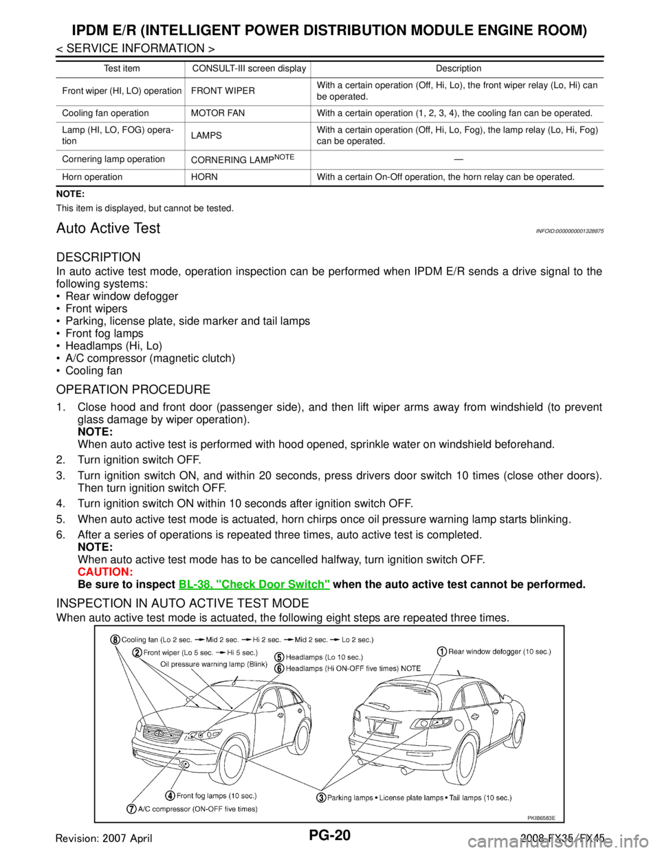
INSPECTION IN AUTO ACTIVE TEST MODE
When auto active test mode is actuated, the following eight steps are repeated three times.
Front wiper (HI, LO) operation FRONT WIPER With a certain operation (Off, Hi, Lo),
the front wiper relay (Lo, Hi) can
be operated.
Cooling fan operation MOTOR FAN With a certain operation (1, 2, 3, 4), the cooling fan can be operated.
Lamp (HI, LO, FOG) opera-
tion LAMPSWith a certain operation (Off, Hi, Lo, Fog), the lamp relay (Lo, Hi, Fog)
can be operated.
Cornering lamp operation CORNERING LAMP
NOTE—
Horn operation HORN With a certain On-Off operation, the horn relay can be operated. Test item CONSULT-III screen display Description
PKIB6583E
3AA93ABC3ACD3AC03ACA3AC03AC63AC53A913A773A893A873A873A8E3A773A983AC73AC93AC03AC3
3A893A873A873A8F3A773A9D3AAF3A8A3A8C3A863A9D3AAF3A8B3A8C
Page 3457 of 3924
PS-2
< SERVICE INFORMATION >
PRECAUTIONS
SERVICE INFORMATION
PRECAUTIONS
Precaution for Supplemental Restraint System (SRS) "AIR BAG" and "SEAT BELT
PRE-TENSIONER"
INFOID:0000000001612911
The Supplemental Restraint System such as “A IR BAG” and “SEAT BELT PRE-TENSIONER”, used along
with a front seat belt, helps to reduce the risk or severi ty of injury to the driver and front passenger for certain
types of collision. This system includes seat belt switch inputs and dual stage front air bag modules. The SRS
system uses the seat belt switches to determine the front air bag deployment, and may only deploy one front
air bag, depending on the severity of a collision and w hether the front occupants are belted or unbelted.
Information necessary to service the system safely is included in the “SUPPLEMENTAL RESTRAINT SYS-
TEM” and “SEAT BELTS” of this Service Manual.
WARNING:
• To avoid rendering the SRS inopera tive, which could increase the risk of personal injury or death in
the event of a collision which would result in air bag inflation, all maintenance must be performed by
an authorized NISS AN/INFINITI dealer.
Improper maintenance, including in correct removal and installation of the SRS, can lead to personal
injury caused by unintent ional activation of the system. For re moval of Spiral Cable and Air Bag
Module, see the “SUPPLEMEN TAL RESTRAINT SYSTEM”.
Do not use electrical test equipmen t on any circuit related to the SRS unless instructed to in this
Service Manual. SRS wiring harnesses can be identi fied by yellow and/or orange harnesses or har-
ness connectors.
Precaution Necessary for Steering W heel Rotation After Battery Disconnect
INFOID:0000000001612914
NOTE:
This Procedure is applied only to models with In telligent Key system and NVIS/IVIS (NISSAN/INFINITI
VEHICLE IMMOBILIZER SYSTEM - NATS).
Remove and install all control units after disconnecting both battery cables with the ignition knob in the ″LOCK ″ position.
Always use CONSULT-III to perform self-diagnosis as a part of each function inspection after finishing work.
If DTC is detected, perform trouble diagnosis according to self-diagnostic results.
For models equipped with the Intelligent Key system and NVIS /IVIS, an electrically controlled steering lock
mechanism is adopted on the key cylinder.
For this reason, if the battery is disconnected or if the battery is discharged, the steering wheel will lock and
steering wheel rotation will become impossible.
If steering wheel rotation is required when battery pow er is interrupted, follow the procedure below before
starting the repair operation.
OPERATION PROCEDURE
1. Connect both battery cables. NOTE:
Supply power using jumper cables if battery is discharged.
2. Use the Intelligent Key or mechanical key to turn the ignition switch to the ″ACC ″ position. At this time, the
steering lock will be released.
3. Disconnect both battery cables. The steering lock will remain released and the steering wheel can be
rotated.
4. Perform the necessary repair operation.
5. When the repair work is completed, return the ignition switch to the ″LOCK ″ position before connecting
the battery cables. (At this time, the steering lock mechanism will engage.)
6. Perform a self-diagnosis check of all control units using CONSULT-III.
Precaution for Steering SystemINFOID:0000000001327705
In case of removing steering gear assembly, make the final tightening with grounded and unloaded vehicle
condition, and then check wheel alignment.
Observe the following precautions when disassembling.
3AA93ABC3ACD3AC03ACA3AC03AC63AC53A913A773A893A873A873A8E3A773A983AC73AC93AC03AC3
3A893A873A873A8F3A773A9D3AAF3A8A3A8C3A863A9D3AAF3A8B3A8C
Page 3482 of 3924
POWER STEERING OIL PUMPPS-27
< SERVICE INFORMATION >
C
DE
F
H I
J
K L
M A
B
PS
N
O P
POWER STEERING OIL PUMP
On-Vehicle Inspection and ServiceINFOID:0000000001327718
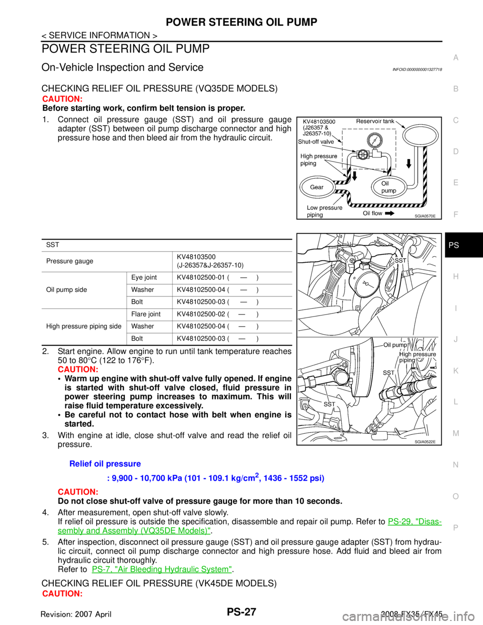
CHECKING RELIEF OIL PRESSURE (VQ35DE MODELS)
CAUTION:
Before starting work, confirm belt tension is proper.
1. Connect oil pressure gauge (SST) and oil pressure gauge adapter (SST) between oil pump discharge connector and high
pressure hose and then bleed air from the hydraulic circuit.
2. Start engine. Allow engine to run until tank temperature reaches 50 to 80 °C (122 to 176 °F).
CAUTION:
Warm up engine with shut-o ff valve fully opened. If engine
is started with shut-off val ve closed, fluid pressure in
power steering pump increases to maximum. This will
raise fluid temperature excessively.
Be careful not to contact hose with belt when engine is
started.
3. With engine at idle, close shut-off valve and read the relief oil pressure.
CAUTION:
Do not close shut-off valve of pressu re gauge for more than 10 seconds.
4. After measurement, open shut-off valve slowly. If relief oil pressure is outside the specificat ion, disassemble and repair oil pump. Refer to PS-29, "
Disas-
sembly and Assembly (VQ35DE Models)".
5. After inspection, disconnect oil pressure gauge ( SST) and oil pressure gauge adapter (SST) from hydrau-
lic circuit, connect oil pump discharge connector and high pressure hose. Add fluid and bleed air from
hydraulic circuit thoroughly.
Refer to PS-7, "
Air Bleeding Hydraulic System".
CHECKING RELIEF OIL PRES SURE (VK45DE MODELS)
CAUTION:
SGIA0570E
SST
Pressure gauge KV48103500
(J-26357&J-26357-10)
Oil pump side Eye joint KV48102500-01 ( — )
Washer KV48102500-04 ( — )
Bolt KV48102500-03 ( — )
High pressure piping side Flare joint KV48102500-02 ( — )
Washer KV48102500-04 ( — )
Bolt KV48102500-03 ( — )
Relief oil pressure
: 9,900 - 10,700 kPa (101 - 109.1 kg/cm
2, 1436 - 1552 psi)
SGIA0522E
3AA93ABC3ACD3AC03ACA3AC03AC63AC53A913A773A893A873A873A8E3A773A983AC73AC93AC03AC3
3A893A873A873A8F3A773A9D3AAF3A8A3A8C3A863A9D3AAF3A8B3A8C
Page 3483 of 3924
PS-28
< SERVICE INFORMATION >
POWER STEERING OIL PUMP
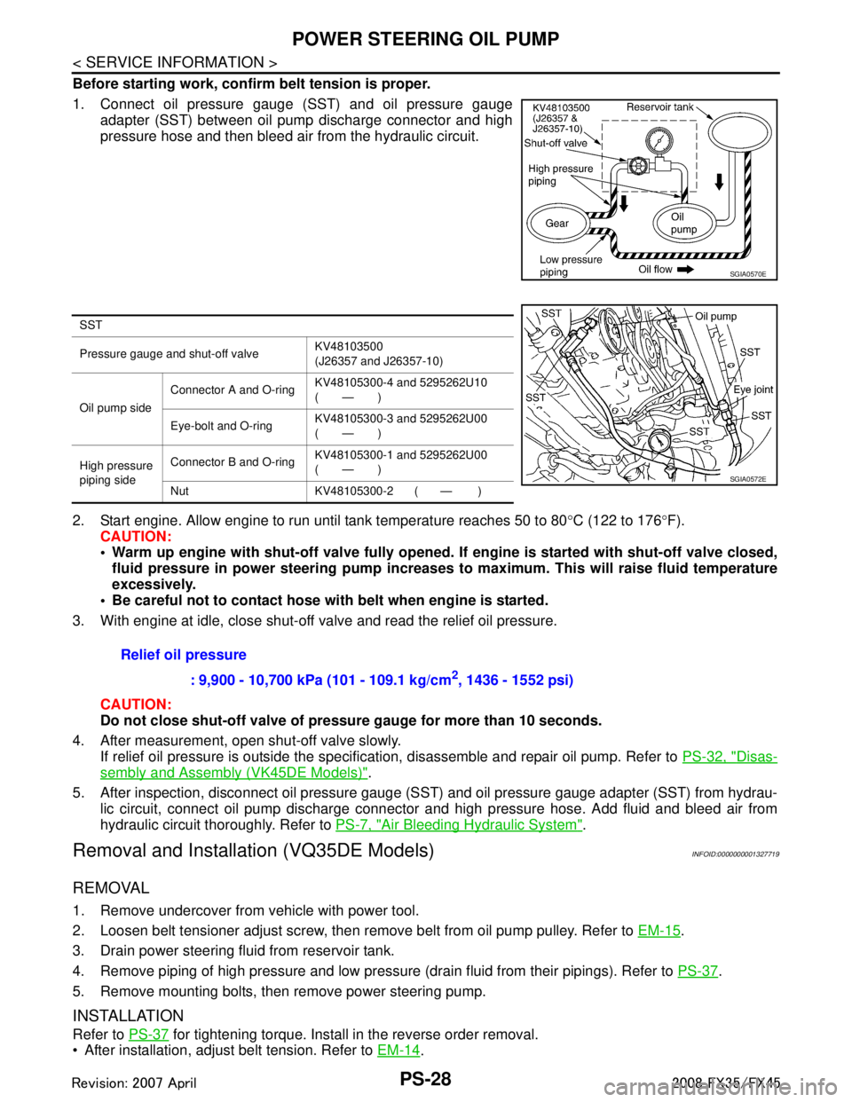
Before starting work, confirm belt tension is proper.
1. Connect oil pressure gauge (SST) and oil pressure gaugeadapter (SST) between oil pump discharge connector and high
pressure hose and then bleed air from the hydraulic circuit.
2. Start engine. Allow engine to run until tank temperature reaches 50 to 80 °C (122 to 176 °F).
CAUTION:
Warm up engine with shut-off val ve fully opened. If engine is started with shut-off valve closed,
fluid pressure in power steering pump increases to maximum. This will raise fluid temperature
excessively.
Be careful not to contact hose with belt when engine is started.
3. With engine at idle, close shut-off valve and read the relief oil pressure.
CAUTION:
Do not close shut-off valve of pressu re gauge for more than 10 seconds.
4. After measurement, open shut-off valve slowly. If relief oil pressure is outside the specification, disassemble and repair oil pump. Refer to PS-32, "
Disas-
sembly and Assembly (VK45DE Models)".
5. After inspection, disconnect oil pressure gauge (S ST) and oil pressure gauge adapter (SST) from hydrau-
lic circuit, connect oil pump discharge connector and high pressure hose. Add fluid and bleed air from
hydraulic circuit thoroughly. Refer to PS-7, "
Air Bleeding Hydraulic System".
Removal and Installation (VQ35DE Models)INFOID:0000000001327719
REMOVAL
1. Remove undercover from vehicle with power tool.
2. Loosen belt tensioner adjust screw, then remove belt from oil pump pulley. Refer to EM-15
.
3. Drain power steering fluid from reservoir tank.
4. Remove piping of high pressure and low pressure (drain fluid from their pipings). Refer to PS-37
.
5. Remove mounting bolts, then remove power steering pump.
INSTALLATION
Refer to PS-37 for tightening torque. Install in the reverse order removal.
After installation, adjust belt tension. Refer to EM-14
.
SGIA0570E
SST
Pressure gauge and shut-off valveKV48103500
(J26357 and J26357-10)
Oil pump side Connector A and O-ring
KV48105300-4 and 5295262U10
(—)
Eye-bolt and O-ring KV48105300-3 and 5295262U00
(—)
High pressure
piping side Connector B and O-ring
KV48105300-1 and 5295262U00
(—)
Nut KV48105300-2 ( — )
SGIA0572E
Relief oil pressure : 9,900 - 10,700 kPa (101 - 109.1 kg/cm
2, 1436 - 1552 psi)
3AA93ABC3ACD3AC03ACA3AC03AC63AC53A913A773A893A873A873A8E3A773A983AC73AC93AC03AC3
3A893A873A873A8F3A773A9D3AAF3A8A3A8C3A863A9D3AAF3A8B3A8C
Page 3487 of 3924
PS-32
< SERVICE INFORMATION >
POWER STEERING OIL PUMP
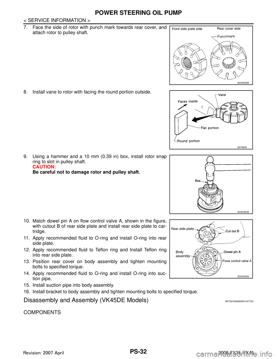
7. Face the side of rotor with punch mark towards rear cover, andattach rotor to pulley shaft.
8. Install vane to rotor with facing the round portion outside.
9. Using a hammer and a 10 mm (0.39 in) box, install rotor snap ring to slot in pulley shaft.
CAUTION:
Be careful not to damage rotor and pulley shaft.
10. Match dowel pin A on flow control valve A, shown in the figure, with cutout B of rear side plate and install rear side plate to car-
tridge.
11. Apply recommended fluid to O-ring and install O-ring into rear side plate.
12. Apply recommended fluid to Teflon ring and Install Teflon ring into rear side plate.
13. Position rear cover on body assembly and tighten mounting bolts to specified torque.
14. Apply recommended fluid to O-ring and install O-ring into suc- tion pipe.
15. Install suction pipe into body assembly.
16. Install bracket to body assembly and tighten mounting bolts to specified torque.
Disassembly and Assemb ly (VK45DE Models)INFOID:0000000001327722
COMPONENTS
SGIA0529E
SST843A
SGIA0063E
SGIA0530E
3AA93ABC3ACD3AC03ACA3AC03AC63AC53A913A773A893A873A873A8E3A773A983AC73AC93AC03AC3
3A893A873A873A8F3A773A9D3AAF3A8A3A8C3A863A9D3AAF3A8B3A8C
Page 3553 of 3924
FRONT OIL SEALRFD-11
< SERVICE INFORMATION >
CEF
G H
I
J
K L
M A
B
RFD
N
O P
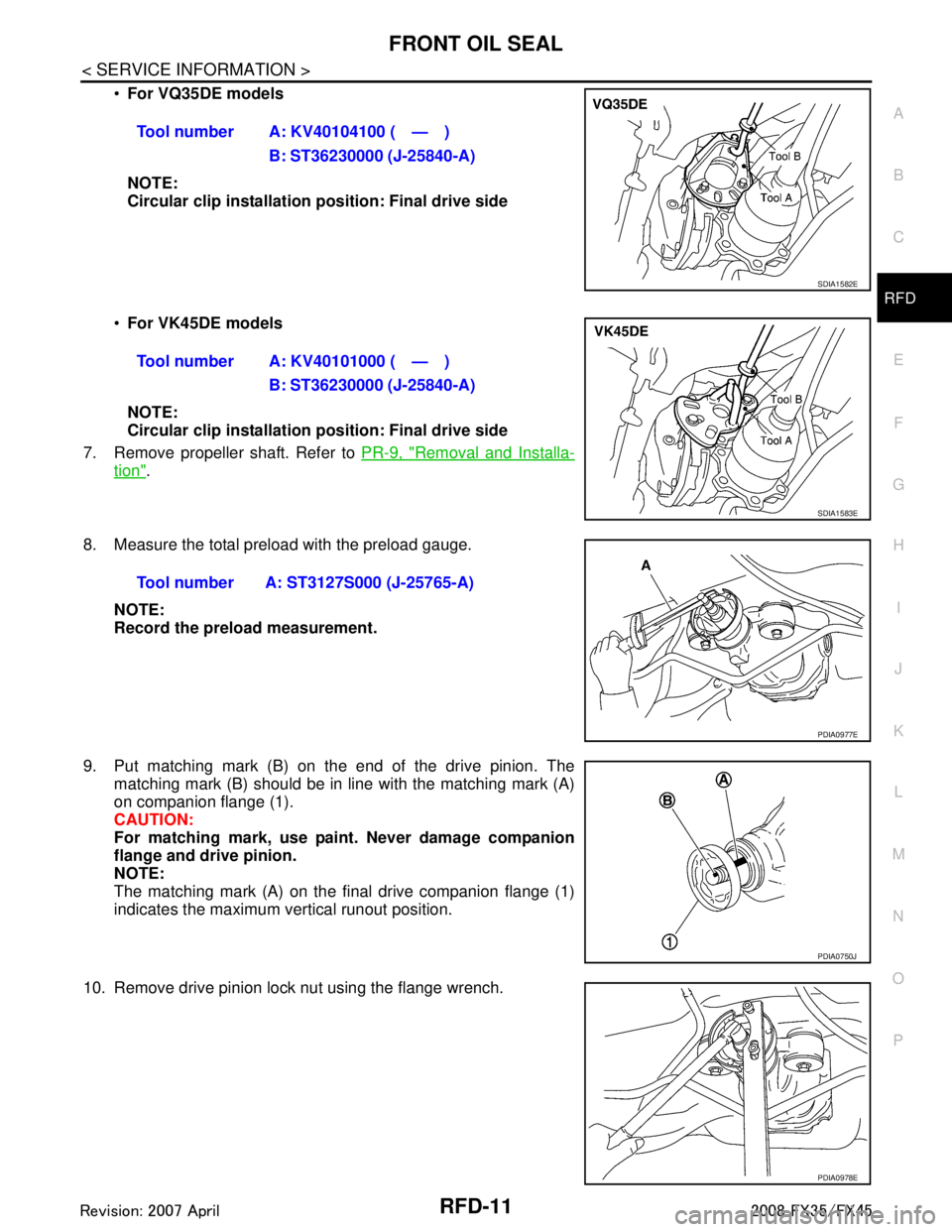
For VQ35DE models
NOTE:
Circular clip installation position: Final drive side
For VK45DE models
NOTE:
Circular clip installation position: Final drive side
7. Remove propeller shaft. Refer to PR-9, "
Removal and Installa-
tion".
8. Measure the total preload with the preload gauge. NOTE:
Record the preload measurement.
9. Put matching mark (B) on the end of the drive pinion. The matching mark (B) should be in line with the matching mark (A)
on companion flange (1).
CAUTION:
For matching mark, use pain t. Never damage companion
flange and drive pinion.
NOTE:
The matching mark (A) on the final drive companion flange (1)
indicates the maximum vertical runout position.
10. Remove drive pinion lock nut using the flange wrench. Tool number A: KV40104100 ( — )
B: ST36230000 (J-25840-A)
SDIA1582E
Tool number A: KV40101000 ( — )B: ST36230000 (J-25840-A)
SDIA1583E
Tool number A: ST3127S000 (J-25765-A)
PDIA0977E
PDIA0750J
PDIA0978E
3AA93ABC3ACD3AC03ACA3AC03AC63AC53A913A773A893A873A873A8E3A773A983AC73AC93AC03AC3
3A893A873A873A8F3A773A9D3AAF3A8A3A8C3A863A9D3AAF3A8B3A8C