2008 INFINITI FX35 washer fluid
[x] Cancel search: washer fluidPage 3462 of 3924
POWER STEERING FLUIDPS-7
< SERVICE INFORMATION >
C
DE
F
H I
J
K L
M A
B
PS
N
O P
POWER STEERING FLUID
Checking Fluid LevelINFOID:0000000001327709
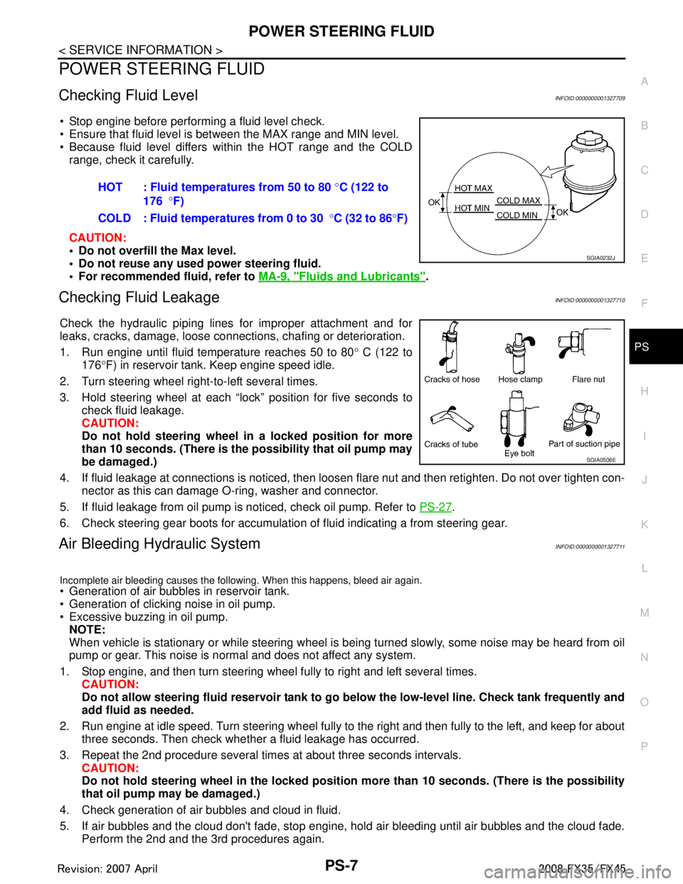
Stop engine before performing a fluid level check.
Ensure that fluid level is between the MAX range and MIN level.
Because fluid level differs within the HOT range and the COLD range, check it carefully.
CAUTION:
Do not overfill the Max level.
Do not reuse any used power steering fluid.
For recommended fluid, refer to MA-9, "
Fluids and Lubricants".
Checking Fluid LeakageINFOID:0000000001327710
Check the hydraulic piping lines for improper attachment and for
leaks, cracks, damage, loose connections, chafing or deterioration.
1. Run engine until fluid temperature reaches 50 to 80 ° C (122 to
176 °F) in reservoir tank. Keep engine speed idle.
2. Turn steering wheel right-to-left several times.
3. Hold steering wheel at each “lock” position for five seconds to check fluid leakage.
CAUTION:
Do not hold steering wheel in a locked position for more
than 10 seconds. (There is the possibility that oil pump may
be damaged.)
4. If fluid leakage at connections is noticed, then loos en flare nut and then retighten. Do not over tighten con-
nector as this can damage O-ring, washer and connector.
5. If fluid leakage from oil pump is noticed, check oil pump. Refer to PS-27
.
6. Check steering gear boots for accumulation of fluid indicating a from steering gear.
Air Bleeding Hydraulic SystemINFOID:0000000001327711
Incomplete air bleeding causes the following. When this happens, bleed air again.
Generation of air bubbles in reservoir tank.
Generation of clicking noise in oil pump.
Excessive buzzing in oil pump. NOTE:
When vehicle is stationary or while steering wheel is being turned slowly, some noise may be heard from oil
pump or gear. This noise is normal and does not affect any system.
1. Stop engine, and then turn steering wheel fully to right and left several times. CAUTION:
Do not allow steering fluid reservoir tank to go below the low-level line. Check tank frequently and
add fluid as needed.
2. Run engine at idle speed. Turn steering wheel fully to the right and then fully to the left, and keep for about
three seconds. Then check whether a fluid leakage has occurred.
3. Repeat the 2nd procedure several times at about three seconds intervals. CAUTION:
Do not hold steering wheel in the locked position more than 10 seconds. (There is the possibility
that oil pump may be damaged.)
4. Check generation of air bubbles and cloud in fluid.
5. If air bubbles and the cloud don't fade, stop engine, hold air bleeding until air bubbles and the cloud fade.
Perform the 2nd and the 3rd procedures again. HOT : Fluid temperatures from 50 to 80
°C (122 to
176 °F)
COLD : Fluid temperatures from 0 to 30 °C (32 to 86 °F)
SGIA0232J
SGIA0506E
3AA93ABC3ACD3AC03ACA3AC03AC63AC53A913A773A893A873A873A8E3A773A983AC73AC93AC03AC3
3A893A873A873A8F3A773A9D3AAF3A8A3A8C3A863A9D3AAF3A8B3A8C
Page 3482 of 3924
POWER STEERING OIL PUMPPS-27
< SERVICE INFORMATION >
C
DE
F
H I
J
K L
M A
B
PS
N
O P
POWER STEERING OIL PUMP
On-Vehicle Inspection and ServiceINFOID:0000000001327718
CHECKING RELIEF OIL PRESSURE (VQ35DE MODELS)
CAUTION:
Before starting work, confirm belt tension is proper.
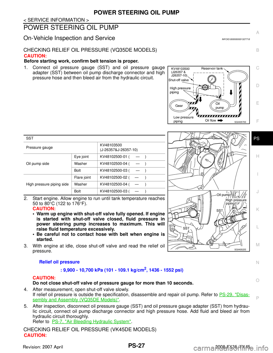
1. Connect oil pressure gauge (SST) and oil pressure gauge adapter (SST) between oil pump discharge connector and high
pressure hose and then bleed air from the hydraulic circuit.
2. Start engine. Allow engine to run until tank temperature reaches 50 to 80 °C (122 to 176 °F).
CAUTION:
Warm up engine with shut-o ff valve fully opened. If engine
is started with shut-off val ve closed, fluid pressure in
power steering pump increases to maximum. This will
raise fluid temperature excessively.
Be careful not to contact hose with belt when engine is
started.
3. With engine at idle, close shut-off valve and read the relief oil pressure.
CAUTION:
Do not close shut-off valve of pressu re gauge for more than 10 seconds.
4. After measurement, open shut-off valve slowly. If relief oil pressure is outside the specificat ion, disassemble and repair oil pump. Refer to PS-29, "
Disas-
sembly and Assembly (VQ35DE Models)".
5. After inspection, disconnect oil pressure gauge ( SST) and oil pressure gauge adapter (SST) from hydrau-
lic circuit, connect oil pump discharge connector and high pressure hose. Add fluid and bleed air from
hydraulic circuit thoroughly.
Refer to PS-7, "
Air Bleeding Hydraulic System".
CHECKING RELIEF OIL PRES SURE (VK45DE MODELS)
CAUTION:
SGIA0570E
SST
Pressure gauge KV48103500
(J-26357&J-26357-10)
Oil pump side Eye joint KV48102500-01 ( — )
Washer KV48102500-04 ( — )
Bolt KV48102500-03 ( — )
High pressure piping side Flare joint KV48102500-02 ( — )
Washer KV48102500-04 ( — )
Bolt KV48102500-03 ( — )
Relief oil pressure
: 9,900 - 10,700 kPa (101 - 109.1 kg/cm
2, 1436 - 1552 psi)
SGIA0522E
3AA93ABC3ACD3AC03ACA3AC03AC63AC53A913A773A893A873A873A8E3A773A983AC73AC93AC03AC3
3A893A873A873A8F3A773A9D3AAF3A8A3A8C3A863A9D3AAF3A8B3A8C
Page 3488 of 3924
POWER STEERING OIL PUMPPS-33
< SERVICE INFORMATION >
C
DE
F
H I
J
K L
M A
B
PS
N
O P
INSPECTION BEFORE DISASSEMBLY
Disassemble power steering oil pump onl y if the following items are found.
Oil leakage from oil pump.
Deformed or damaged pulley
Poor performance
DISASSEMBLY
NOTE:
Fix oil pump in vise as the occasion demands.
CAUTION:
When retaining drive shaft in a vise, always use copper or alumi num plates between vise and shaft.
1. Unscrew three bracket bolts and remove bracket from rear cover.
2. Unscrew four rear cover bolts and remove rear cover from body assembly.
3. Remove gasket from body assembly.
4. Remove lock pin, cartridge and side plate from body assembly.
5. Remove pulley from drive shaft assembly.
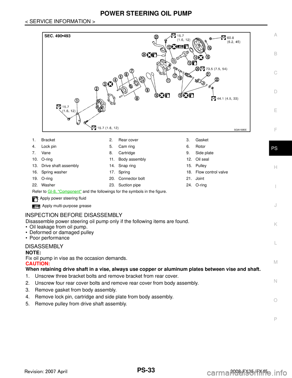
1. Bracket 2. Rear cover 3. Gasket
4. Lock pin 5. Cam ring 6. Rotor
7. Vane 8. Cartridge 9. Side plate
10. O-ring 11. Body assembly 12. Oil seal
13. Drive shaft assembly 14. Snap ring 15. Pulley
16. Spring washer 17. Spring 18. Flow control valve
19. O-ring 20. Connector bolt 21. Joint
22. Washer 23. Suction pipe 24. O-ring
Refer to GI-8, "
Component" and the followings for the symbols in the figure.
: Apply power steering fluid
: Apply multi-purpose grease
SGIA1680E
3AA93ABC3ACD3AC03ACA3AC03AC63AC53A913A773A893A873A873A8E3A773A983AC73AC93AC03AC3
3A893A873A873A8F3A773A9D3AAF3A8A3A8C3A863A9D3AAF3A8B3A8C
Page 3491 of 3924
PS-36
< SERVICE INFORMATION >
POWER STEERING OIL PUMP
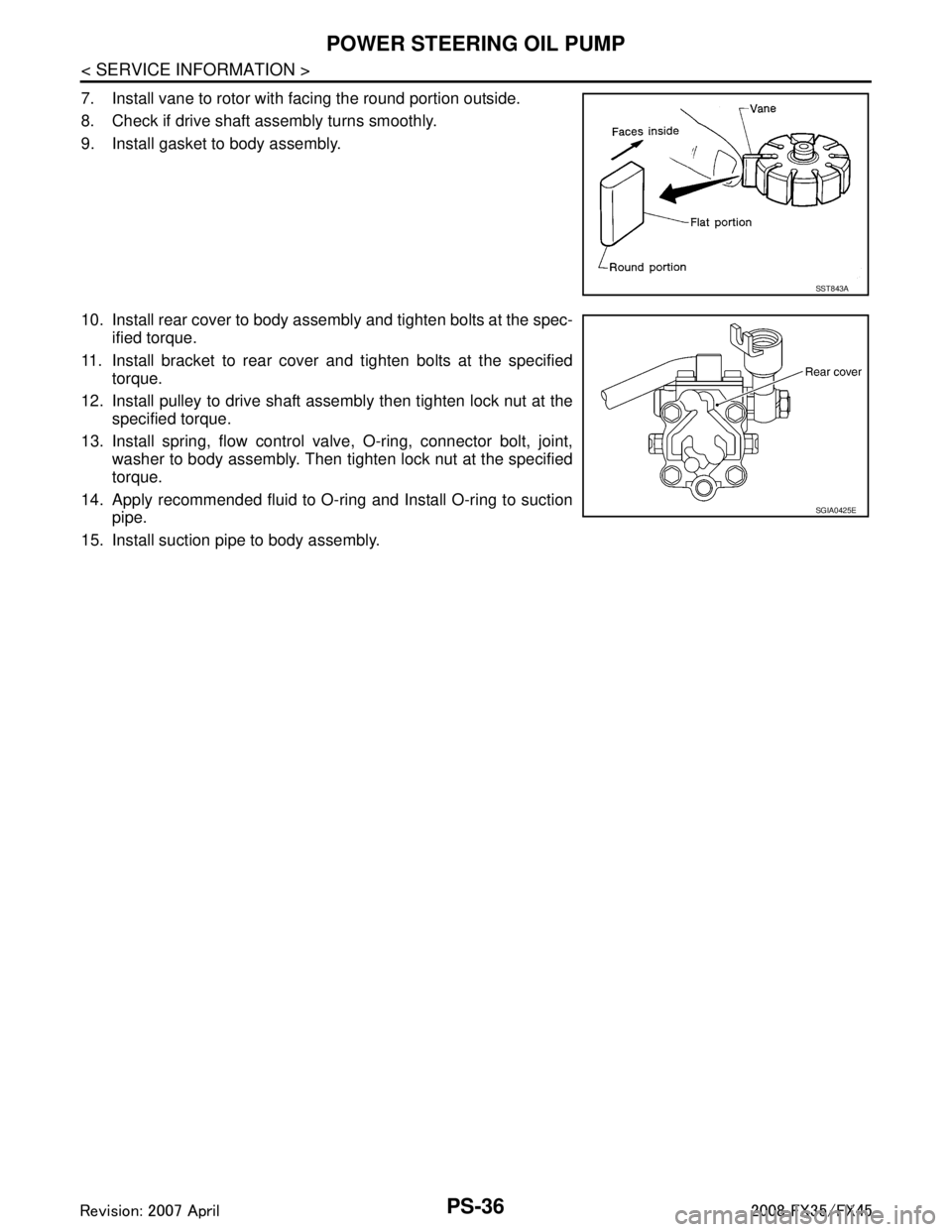
7. Install vane to rotor with facing the round portion outside.
8. Check if drive shaft assembly turns smoothly.
9. Install gasket to body assembly.
10. Install rear cover to body assembly and tighten bolts at the spec-ified torque.
11. Install bracket to rear cover and tighten bolts at the specified torque.
12. Install pulley to drive shaft assembly then tighten lock nut at the specified torque.
13. Install spring, flow control valve, O-ring, connector bolt, joint, washer to body assembly. Then tighten lock nut at the specified
torque.
14. Apply recommended fluid to O-ring and Install O-ring to suction pipe.
15. Install suction pipe to body assembly.
SST843A
SGIA0425E
3AA93ABC3ACD3AC03ACA3AC03AC63AC53A913A773A893A873A873A8E3A773A983AC73AC93AC03AC3
3A893A873A873A8F3A773A9D3AAF3A8A3A8C3A863A9D3AAF3A8B3A8C
Page 3492 of 3924
HYDRAULIC LINEPS-37
< SERVICE INFORMATION >
C
DE
F
H I
J
K L
M A
B
PS
N
O P
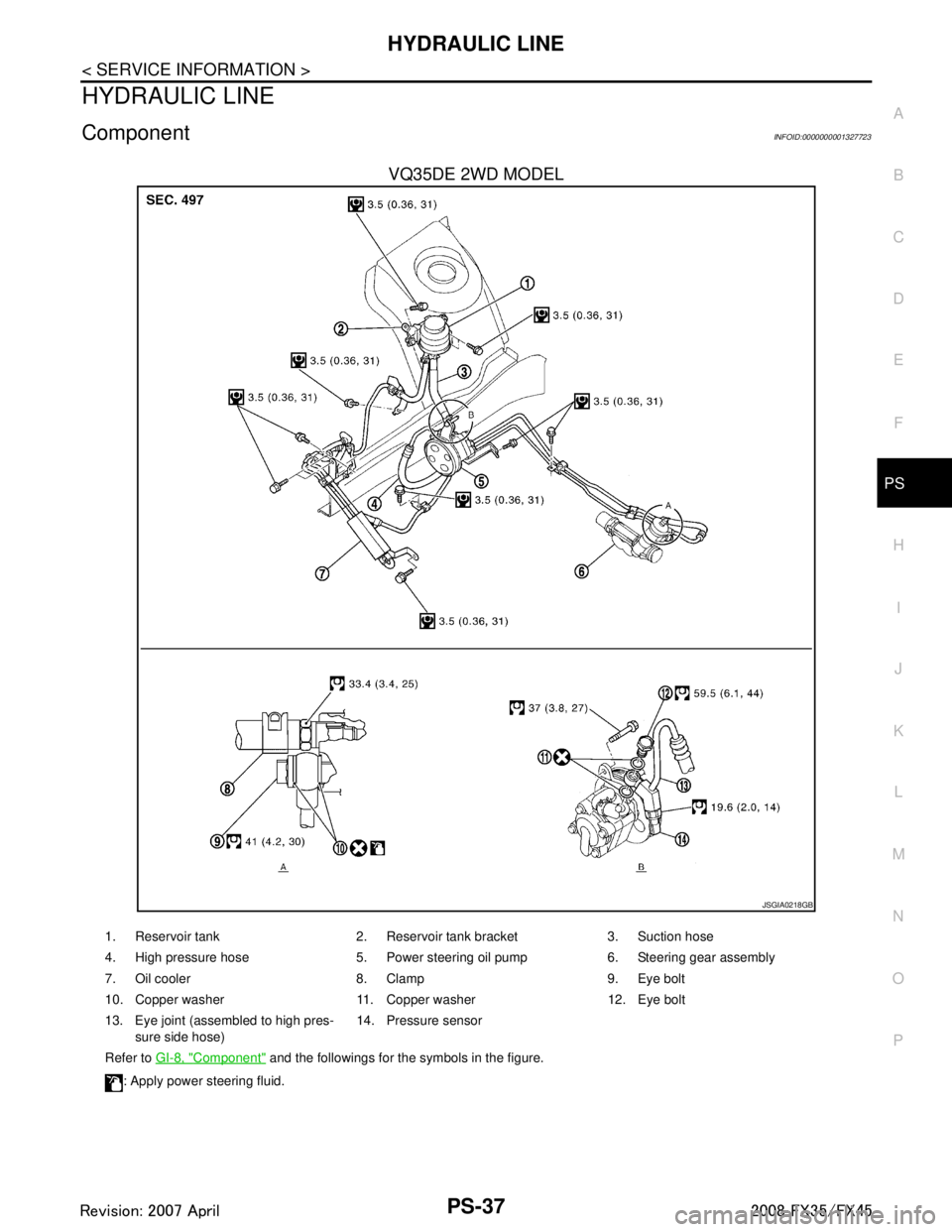
HYDRAULIC LINE
ComponentINFOID:0000000001327723
VQ35DE 2WD MODEL
JSGIA0218GB
1. Reservoir tank 2. Reservoir tank bracket 3. Suction hose
4. High pressure hose 5. Power steering oil pump 6. Steering gear assembly
7. Oil cooler 8. Clamp 9. Eye bolt
10. Copper washer 11. Copper washer 12. Eye bolt
13. Eye joint (assembled to high pres- sure side hose) 14. Pressure sensor
Refer to GI-8, "
Component" and the followings for the symbols in the figure.
: Apply power steering fluid.
3AA93ABC3ACD3AC03ACA3AC03AC63AC53A913A773A893A873A873A8E3A773A983AC73AC93AC03AC3
3A893A873A873A8F3A773A9D3AAF3A8A3A8C3A863A9D3AAF3A8B3A8C
Page 3493 of 3924

PS-38
< SERVICE INFORMATION >
HYDRAULIC LINE
VQ35DE AWD MODEL
JSGIA0177GB
1. Reservoir tank 2. Reservoir tank bracket 3. Suction hose
4. High pressure hose 5. Power steering oil pump 6. Steering gear assembly
7. Oil cooler 8. Clamp 9. Eye bolt
10. Copper washer 11. Eye bolt 12. Copper washer
13. Oil pressure sensor
Refer to GI-8, "
Component" and the followings for the symbols in the figure.
: Apply power steering fluid.
3AA93ABC3ACD3AC03ACA3AC03AC63AC53A913A773A893A873A873A8E3A773A983AC73AC93AC03AC3
3A893A873A873A8F3A773A9D3AAF3A8A3A8C3A863A9D3AAF3A8B3A8C
Page 3494 of 3924
HYDRAULIC LINEPS-39
< SERVICE INFORMATION >
C
DE
F
H I
J
K L
M A
B
PS
N
O P
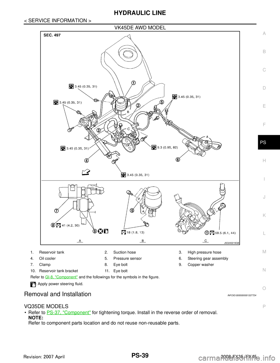
VK45DE AWD MODEL
Removal and InstallationINFOID:0000000001327724
VQ35DE MODELS
Refer to PS-37, "Component" for tightening torque. Install in the reverse order of removal.
NOTE:
Refer to component parts location and do not reuse non-reusable parts.
JSGIA0219GB
1. Reservoir tank 2. Suction hose 3. High pressure hose
4. Oil cooler 5. Pressure sensor 6. Steering gear assembly
7. Clamp 8. Eye bolt 9. Copper washer
10. Reservoir tank bracket 11. Eye bolt
Refer to GI-8, "
Component" and the followings for the symbols in the figure.
: Apply power steering fluid.
3AA93ABC3ACD3AC03ACA3AC03AC63AC53A913A773A893A873A873A8E3A773A983AC73AC93AC03AC3
3A893A873A873A8F3A773A9D3AAF3A8A3A8C3A863A9D3AAF3A8B3A8C
Page 3899 of 3924
WW-24
< SERVICE INFORMATION >
FRONT WIPER AND WASHER SYSTEM
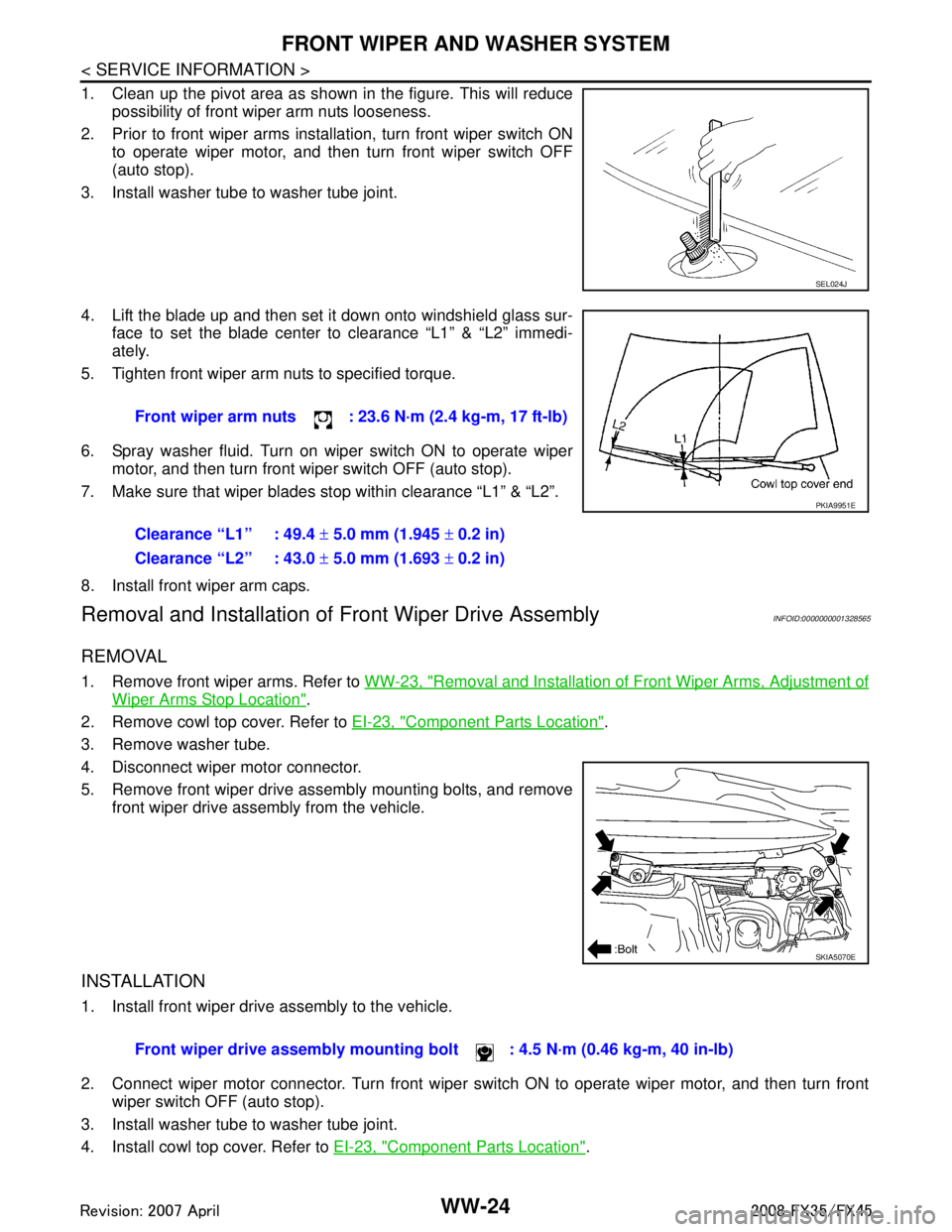
1. Clean up the pivot area as shown in the figure. This will reducepossibility of front wiper arm nuts looseness.
2. Prior to front wiper arms installation, turn front wiper switch ON to operate wiper motor, and then turn front wiper switch OFF
(auto stop).
3. Install washer tube to washer tube joint.
4. Lift the blade up and then set it down onto windshield glass sur- face to set the blade center to clearance “L1” & “L2” immedi-
ately.
5. Tighten front wiper arm nuts to specified torque.
6. Spray washer fluid. Turn on wiper switch ON to operate wiper motor, and then turn front wiper switch OFF (auto stop).
7. Make sure that wiper blades stop within clearance “L1” & “L2”.
8. Install front wiper arm caps.
Removal and Installation of Front Wiper Drive AssemblyINFOID:0000000001328565
REMOVAL
1. Remove front wiper arms. Refer to WW-23, "Removal and Installation of Front Wiper Arms, Adjustment of
Wiper Arms Stop Location".
2. Remove cowl top cover. Refer to EI-23, "
Component Parts Location".
3. Remove washer tube.
4. Disconnect wiper motor connector.
5. Remove front wiper drive assembly mounting bolts, and remove front wiper drive assembly from the vehicle.
INSTALLATION
1. Install front wiper drive assembly to the vehicle.
2. Connect wiper motor connector. Turn front wiper switch ON to operate wiper motor, and then turn frontwiper switch OFF (auto stop).
3. Install washer tube to washer tube joint.
4. Install cowl top cover. Refer to EI-23, "
Component Parts Location".
SEL024J
Front wiper arm nuts : 23.6 N·m (2.4 kg-m, 17 ft-lb)
Clearance “L1” : 49.4 ± 5.0 mm (1.945 ± 0.2 in)
Clearance “L2” : 43.0 ± 5.0 mm (1.693 ± 0.2 in)
PKIA9951E
SKIA5070E
Front wiper drive assembly mounting bo lt : 4.5 N·m (0.46 kg-m, 40 in-lb)
3AA93ABC3ACD3AC03ACA3AC03AC63AC53A913A773A893A873A873A8E3A773A983AC73AC93AC03AC3
3A893A873A873A8F3A773A9D3AAF3A8A3A8C3A863A9D3AAF3A8B3A8C