2008 INFINITI FX35 reset
[x] Cancel search: resetPage 1948 of 3924
![INFINITI FX35 2008 Service Manual
EC-708
< SERVICE INFORMATION >[VK45DE]
TROUBLE DIAGNOSIS
*: Accelerator pedal position sensor 2 signal and throttle position sensor 2 signal are converted by ECM internally. Thus, they
differ from
E INFINITI FX35 2008 Service Manual
EC-708
< SERVICE INFORMATION >[VK45DE]
TROUBLE DIAGNOSIS
*: Accelerator pedal position sensor 2 signal and throttle position sensor 2 signal are converted by ECM internally. Thus, they
differ from
E](/manual-img/42/57017/w960_57017-1947.png)
EC-708
< SERVICE INFORMATION >[VK45DE]
TROUBLE DIAGNOSIS
*: Accelerator pedal position sensor 2 signal and throttle position sensor 2 signal are converted by ECM internally. Thus, they
differ from
ECM terminals voltage signal. HO2S2 HTR (B1)
HO2S2 HTR (B2)
Engine speed: Below 3,600 rpm after the following conditions are met.
- Engine: After warming up
- Keeping the engine speed between 3,500 and 4,000 rpm for 1 minute and at
idle for 1 minute under no load ON
Engine speed: Above 3,600 rpm OFF
I/P PULLY SPD Vehicle speed: More than 20 km/h (12 MPH) Almost the same speed as
the tachometer indication
VEHICLE SPEED Turn drive wheels and compare CONSULT-III value with the speedometer in-
dication. Almost the same speed as
the speedometer indication
TRVL AFTER MIL Ignition switch: ON Vehicle has traveled after MIL has turned
ON.0 - 65,535 km
(0 - 40,723 miles)
SNOW MODE SW Ignition switch: ON Snow mode switch: ON ON
Snow mode switch: OFF OFF
A/F S1 HTR (B1)
A/F S1 HTR (B2) Engine: After warming up, idle the engine 0 - 100%
AC PRESS SEN Engine: Idle
Both air conditioner switch and blower fan switch: ON (Compressor operates)
1.0 - 4.0V
VHCL SPEED SE Turn drive wheels and compare CONSULT-III value with the speedometer in-
dication. Almost the same speed as
the speedometer indication
SET VHCL SPD Engine: Running ASCD: Operating The preset vehicle speed is
displayed
MAIN SW Ignition switch: ON MAIN switch: Pressed ON
MAIN switch: Released OFF
CANCEL SW Ignition switch: ON CANCEL switch: Pressed ON
CANCEL switch: Released OFF
RESUME/ACC SW Ignition switch: ON RESUME/ACCELERATE switch:
Pressed
ON
RESUME/ACCELERATE switch: Re-
leased OFF
SET SW Ignition switch: ON SET/COAST switch: Pressed ON
SET/COAST switch: Released OFF
BRAKE SW1
(ICC/ASCD brake
switch) Ignition switch: ON Brake pedal: Fully released ON
Brake pedal: Slightly depressed OFF
BRAKE SW2
(Stop lamp switch) Ignition switch: ON Brake pedal: Fully released OFF
Brake pedal: Slightly depressed ON
DIST SW Ignition switch: ON DISTANCE switch: Pressed ON
DISTANCE switch: Released OFF
CRUISE LAMP Ignition switch: ON MAIN switch: Pressed at the 1st time
→
at the 2nd time ON
→ OFF
SET LAMP MAIN switch: ON
When vehicle speed is between
40 km/h (25 MPH) and 144 km/h
(89 MPH) ASCD: Operating ON
ASCD: Not operating OFF
MONITOR ITEM CONDITION SPECIFICATION
3AA93ABC3ACD3AC03ACA3AC03AC63AC53A913A773A893A873A873A8E3A773A983AC73AC93AC03AC3
3A893A873A873A8F3A773A9D3AAF3A8A3A8C3A863A9D3AAF3A8B3A8C
Page 2965 of 3924
GW-52
< SERVICE INFORMATION >
FRONT DOOR GLASS AND REGULATOR
Inspection after Removal
Check the regulator assembly for the following. If a malfunction is
detected, replace or grease it.
Wire wear
Regulator deformation
Grease condition for each sliding part
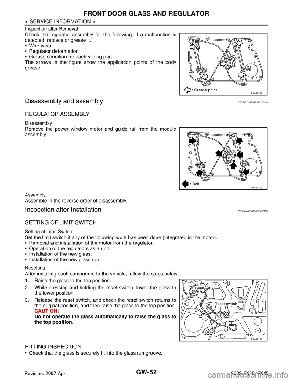
The arrows in the figure show the application points of the body
grease.
Disassembly and assemblyINFOID:0000000001327991
REGULATOR ASSEMBLY
Disassembly
Remove the power window motor and guide rail from the module
assembly.
Assembly
Assemble in the reverse order of disassembly.
Inspection after InstallationINFOID:0000000001327992
SETTING OF LIMIT SWITCH
Setting of Limit Switch
Set the limit switch if any of the following work has been done (integrated in the motor).
Removal and installation of the motor from the regulator.
Operation of the regulators as a unit.
Installation of the new glass.
Installation of the new glass run.
Resetting
After installing each component to the vehicle, follow the steps below.
1. Raise the glass to the top position.
2. While pressing and holding the reset switch, lower the glass to the lower position.
3. Release the reset switch, and check the reset switch returns to the original position, and then rais e the glass to the top position.
CAUTION:
Do not operate the glass automa tically to raise the glass to
the top position.
FITTING INSPECTION
Check that the glass is securely fit into the glass run groove.
PIIA4730E
PIIA4731E
PIIA4732E
3AA93ABC3ACD3AC03ACA3AC03AC63AC53A913A773A893A873A873A8E3A773A983AC73AC93AC03AC3
3A893A873A873A8F3A773A9D3AAF3A8A3A8C3A863A9D3AAF3A8B3A8C
Page 2971 of 3924
GW-58
< SERVICE INFORMATION >
INSIDE MIRROR
Removal and Installation
INFOID:0000000001327997
REMOVAL
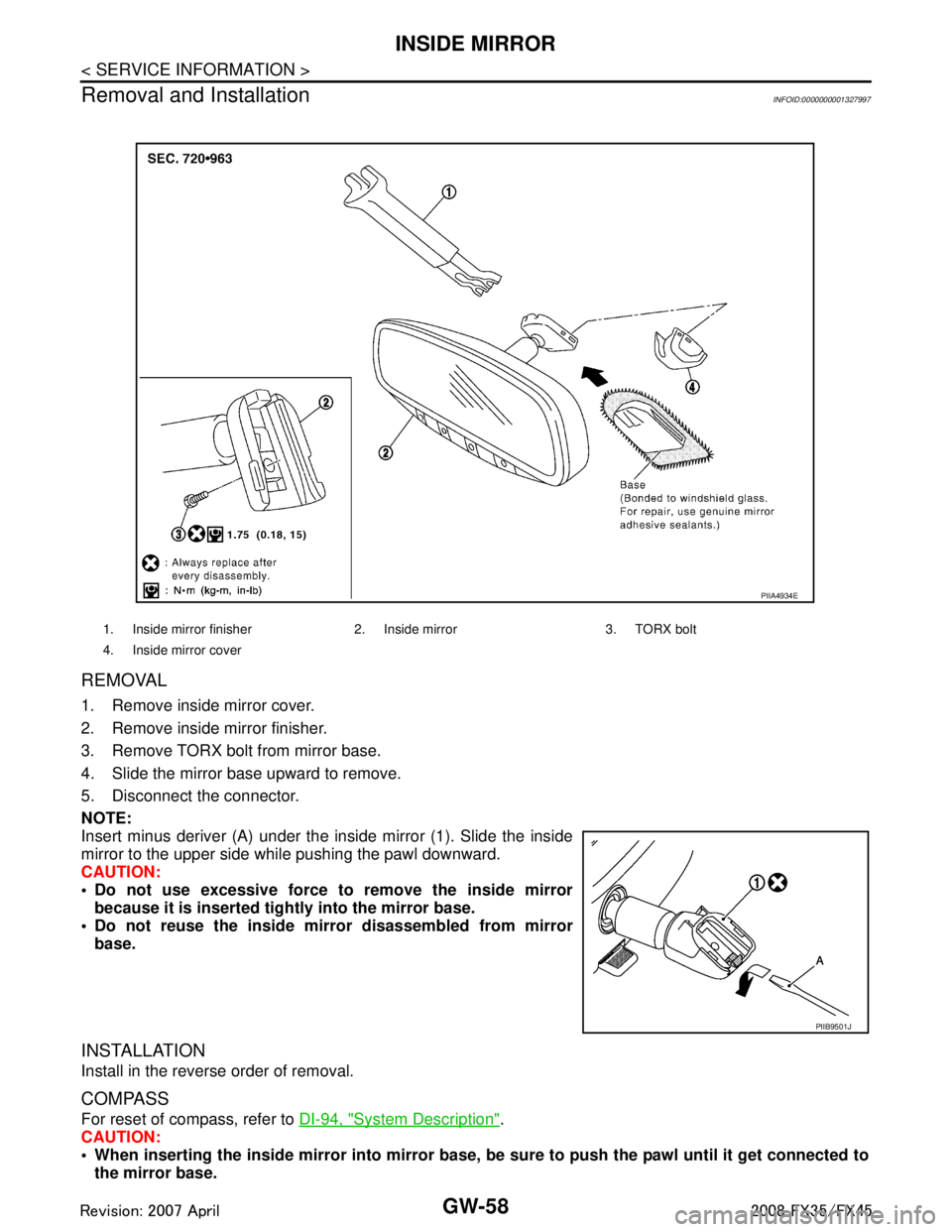
1. Remove inside mirror cover.
2. Remove inside mirror finisher.
3. Remove TORX bolt from mirror base.
4. Slide the mirror base upward to remove.
5. Disconnect the connector.
NOTE:
Insert minus deriver (A) under the inside mirror (1). Slide the inside
mirror to the upper side while pushing the pawl downward.
CAUTION:
Do not use excessive force to remove the inside mirror because it is inserted tightly into the mirror base.
Do not reuse the inside mi rror disassembled from mirror
base.
INSTALLATION
Install in the reverse order of removal.
COMPASS
For reset of compass, refer to DI-94, "System Description".
CAUTION:
When inserting the inside mirror into mirror base, be sure to push the pawl until it get connected to
the mirror base.
1. Inside mirror finisher 2. In side mirror 3. TORX bolt
4. Inside mirror cover
PIIA4934E
PIIB9501J
3AA93ABC3ACD3AC03ACA3AC03AC63AC53A913A773A893A873A873A8E3A773A983AC73AC93AC03AC3
3A893A873A873A8F3A773A9D3AAF3A8A3A8C3A863A9D3AAF3A8B3A8C
Page 3526 of 3924
SUNROOFRF-11
< SERVICE INFORMATION >
C
DE
F
G H
J
K L
M A
B
RF
N
O P
to BCM terminal 49 and 52
through body grounds M35, M45, M85 and R6.
TILT UP / SLIDE CLOSE OPERATION
When tilt up / slide close switch is pressed,
Ground is supplied
to sunroof motor assembly terminal 1
through sunroof switch terminal 3
through sunroof switch terminal 2
through body grounds M35, M45, M85 and R6.
Then, the sunroof tilt up / slide close.
TILT DOWN / SLIDE OPEN OPERATION
When tilt down / slide open switch is pressed,
Ground is supplied
to sunroof motor assembly terminal 5
through sunroof switch terminal 1
through sunroof switch terminal 2
through body grounds M35, M45, M85 and R6.
Then, the sunroof tilt down / slide open.
AUTO OPERATION
The power sunroof AUTO feature makes it possible to slide open and slide close or tilt up and tilt down the
sunroof without holding the sunroof switch in the down or up / tilt up or tilt down position.
RETAINED POWER OPERATION
When the ignition switch is turned to OFF position fr om ON position, power is supplied for 45 seconds.
through BCM terminal 53.
to sunroof motor assembly terminal 9.
When power is supplied, the sunroof can be operated.
The retained power operation is canceled when the driver or passenger side door is opened.
RAP signal period can be changed by CONSULT-III. Refer to RF-15, "
CONSULT-III Function (BCM)".
ANTI-PINCH FUNCTION
The CPU of sunroof motor monitors the sunroof motor operation and the sunroof position (fully-closed or
other) by the signals from sunroof motor.
When sunroof motor detects an interruption during the following slide close and tilt down operation, sunroof
switch controls the motor for open and the sunroof will operate until full up position (when tilt down operate) or
125 mm (4.92 in) or more in an open direction (when slide close operate).
close operation and tilt down when ignition switch is in the ON position.
close operation and tilt down during retained power operation.
MEMORY RESET PROCEDURE
1. Please observe the following instructions while confirming the sunroof operation.
NOTE:
Do not disconnect the electronic power while the sunroof is operating or within 5 seconds after the sunroof
stops. (to wipe-out the memory of lid position and operating friction.)
2. Initialization of system should be conducted after the following conditions.
When the battery is out or connector is disconnected wh ile sunroof is operating or within 5 seconds after
sunroof stops.
When the sunroof motor is changed.
When an emergency handle is used.
When the sunroof does not operate normally. (Incomplete initialization conditions)
INITIALIZATION PROCEDURE
If the sunroof does not close or open automatically, us e the following procedure to return sunroof operation to
normal.
1. Close the sunroof if it is not in the closed positi on. It may be necessary to repeatedly push the switch to
close the sunroof.
2. Press and hold the TILT UP switch. Do not release the switch, keep pressure on it. After 10 seconds of
depressing, the sunroof will tilt up, then stop. Release the button.
3AA93ABC3ACD3AC03ACA3AC03AC63AC53A913A773A893A873A873A8E3A773A983AC73AC93AC03AC3
3A893A873A873A8F3A773A9D3AAF3A8A3A8C3A863A9D3AAF3A8B3A8C
Page 3652 of 3924
AUTOMATIC DRIVE POSITIONERSE-13
< SERVICE INFORMATION >
C
DE
F
G H
J
K L
M A
B
SE
N
O P
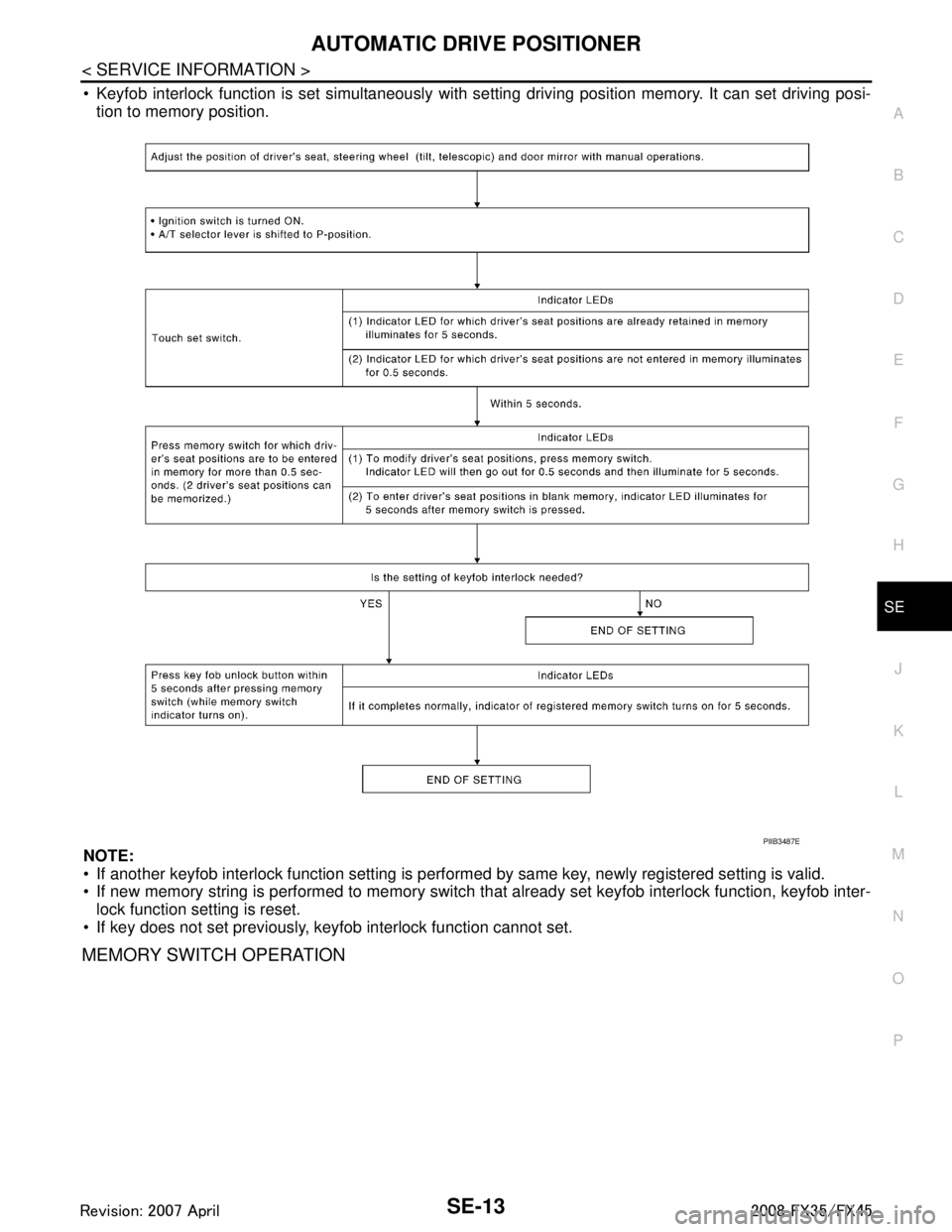
Keyfob interlock function is set simultaneously with se tting driving position memory. It can set driving posi-
tion to memory position.
NOTE:
If another keyfob interlock function setting is perform ed by same key, newly registered setting is valid.
If new memory string is performed to memory switch t hat already set keyfob interlock function, keyfob inter-
lock function setting is reset.
If key does not set previously, keyfob interlock function cannot set.
MEMORY SWITCH OPERATION
PIIB3487E
3AA93ABC3ACD3AC03ACA3AC03AC63AC53A913A773A893A873A873A8E3A773A983AC73AC93AC03AC3
3A893A873A873A8F3A773A9D3AAF3A8A3A8C3A863A9D3AAF3A8B3A8C
Page 3676 of 3924
AUTOMATIC DRIVE POSITIONERSE-37
< SERVICE INFORMATION >
C
DE
F
G H
J
K L
M A
B
SE
N
O P
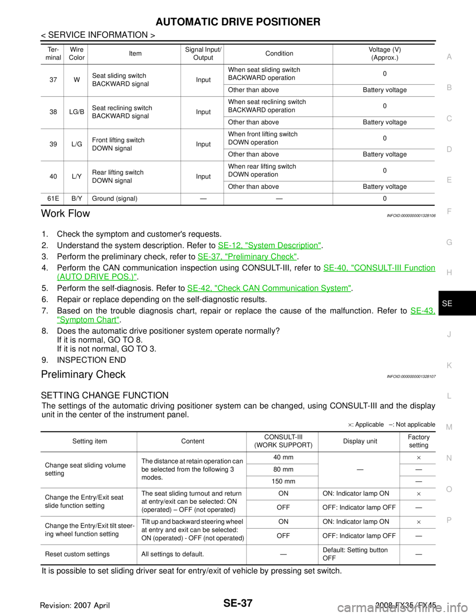
Work FlowINFOID:0000000001328106
1. Check the symptom and customer's requests.
2. Understand the system description. Refer to SE-12, "
System Description".
3. Perform the preliminary check, refer to SE-37, "
Preliminary Check".
4. Perform the CAN communication inspec tion using CONSULT-III, refer to SE-40, "
CONSULT-III Function
(AUTO DRIVE POS.)".
5. Perform the self-diagnosis. Refer to SE-42, "
Check CAN Communication System".
6. Repair or replace depending on the self-diagnostic results.
7. Based on the trouble diagnosis chart, repair or replace the cause of the malfunction. Refer to SE-43,
"Symptom Chart".
8. Does the automatic drive pos itioner system operate normally?
If it is normal, GO TO 8.
If it is not normal, GO TO 3.
9. INSPECTION END
Preliminary CheckINFOID:0000000001328107
SETTING CHANGE FUNCTION
The settings of the automatic driving positioner system can be changed, using CONSULT-III and the display
unit in the center of the instrument panel.
× : Applicable –: Not applicable
It is possible to set sliding driver seat fo r entry/exit of vehicle by pressing set switch.
37 WSeat sliding switch
BACKWARD signal
InputWhen seat sliding switch
BACKWARD operation
0
Other than above Battery voltage
38 LG/B Seat reclining switch
BACKWARD signal InputWhen seat reclining switch
BACKWARD operation
0
Other than above Battery voltage
39 L/G Front lifting switch
DOWN signal InputWhen front lifting switch
DOWN operation
0
Other than above Battery voltage
40 L/Y Rear lifting switch
DOWN signal
InputWhen rear lifting switch
DOWN operation
0
Other than above Battery voltage
61E B/Y Ground (signal) — — 0 Te r -
minal Wire
Color ItemSignal Input/
Output Condition Voltage (V)
(Approx.)
Setting item Content CONSULT-III
(WORK SUPPORT) Display unitFactory
setting
Change seat sliding volume
setting The distance at retain operation can
be selected from the following 3
modes. 40 mm
—×
80 mm —
150 mm —
Change the Entry/Exit seat
slide function setting The seat sliding turnout and return
at entry/exit can be selected: ON
(operated) – OFF (not operated) ON ON: Indicator lamp ON
×
OFF OFF: Indicator lamp OFF —
Change the Entry/Exit tilt steer-
ing wheel function setting Tilt up and backward steering wheel
at entry and exit can be selected:
ON (operated) - OFF (not operated) ON ON: Indicator lamp ON
×
OFF OFF: Indicator lamp OFF —
Reset custom settings All settings to default. — Default: Setting button
OFF
—
3AA93ABC3ACD3AC03ACA3AC03AC63AC53A913A773A893A873A873A8E3A773A983AC73AC93AC03AC3
3A893A873A873A8F3A773A9D3AAF3A8A3A8C3A863A9D3AAF3A8B3A8C
Page 3681 of 3924

SE-42
< SERVICE INFORMATION >
AUTOMATIC DRIVE POSITIONER
ACTIVE TEST
CAUTION:
During vehicle driving, do not perform active test.
NOTE:
If active test is performed, reset seat memory and key fob interlock drive positioner after performing work.
Display Item List
Check CAN Communication SystemINFOID:0000000001532368
1.PERFORM SELF DIAGNOSTIC
1. Turn ignition switch ON and wait for 2 seconds or more.
2. Check “Self Diagnostic Result” of BCM.
TILT SW-UP “ON/OFF” ON/OFF status judged from the tilt switch (UP) signal is displayed.
TILT SW-DOWN “ON/OFF” ON/OFF status judged from the tilt switch (DOWN) signal is displayed.
SET SW “ON/OFF” ON/OFF status judged from the setting switch signal is displayed.
MEMORY SW1 “ON/OFF” ON/OFF status judged from th e seat memory switch 1 signal is displayed.
MEMORY SW2 “ON/OFF” ON/OFF status judged from th e seat memory switch 2 signal is displayed.
P POSI SW “ON/OFF” The selector lever position “ON (P position) / OFF (other than P position)” judged
from the park position switch signal is displayed.
STARTER SW “ON/OFF” Ignition key switch ON (START, ON) /OFF (ignition switch IGN, ACC, or OFF) sta-
tus judged from the ignition switch signal is displayed.
SLIDE PULSE — Value (32768) when battery connects is as standard. If it moves backward, the val-
ue increases. If it moves forward, the value decreases.
RECLN RULSE — Value (32768) when battery connects is as standard. If it moves backward, the val-
ue increases. If it moves forward, the value decreases.
LIFT FR PULSE — Value (32768) when battery connects is as standard. If it moves DOWN, the value
increases. If it moves UP, the value decreases.
LIFT RR PULSE — Value (32768) when battery connects is as standard. If it moves DOWN, the value
increases. If it moves UP, the value decreases.
TILT SEN “V” The tilt position (voltage) judged from the tilt sensor signal is displayed.
TELESCO SEN “V” The telescoping position (voltage) judged from the telescoping sensor signal is dis-
played.
MIR/SE RH R–L “V” Voltage output from RH do or mirror sensor (LH/RH) is displayed.
MIR/SE RH U–D “V” Voltage output from RH door mirror sensor (UP/DOWN) is displayed.
MIR/SE LH R–L “V” Voltage output from LH door mirror sensor (LH/RH) is displayed.
MIR/SE LH U–D “V” Voltage output from LH door mirror sensor (UP/DOWN) is displayed. Monitor item [OPERAT
ION or UNIT] Contents
Test item Description
TILT MOTOR The tilt motor is activated by receiving the drive signal.
TELESCO MOTOR The telescopic motor is activated by receiving the drive signal.
SEAT SLIDE The sliding motor is activated by receiving the drive signal.
SEAT RECLINING The reclining motor is activated by receiving the drive signal.
SEAT LIFTER FR The front end lifter motor is activated by receiving the drive signal.
SEAT LIFTER RR The rear end lifter motor is activated by receiving the drive signal.
MEMORY SW INDCTR The memory sw itch indicator is lit by receivin g the drive signal.
MIRROR MOTOR RH The RH mirror motor moves the mirror UP/DOW
N and LEFT/RIGHT by receiving the drive
signal.
MIRROR MOTOR LH The LH mirror motor moves the mirror UP/DOW
N and LEFT/RIGHT by receiving the drive
signal.
3AA93ABC3ACD3AC03ACA3AC03AC63AC53A913A773A893A873A873A8E3A773A983AC73AC93AC03AC3
3A893A873A873A8F3A773A9D3AAF3A8A3A8C3A863A9D3AAF3A8B3A8C
Page 3759 of 3924
SRS-22
< SERVICE INFORMATION >
TROUBLE DIAGNOSIS
Diagnosis results previously stored in the memory are displayed on the CONSULT-III screen. The stored
results are not erased until memory erasing is executed.
“TROUBLE DIAG RECORD”
With TROUBLE DIAG RECORD, diagnosis results previ ously erased by a reset operation can be displayed
on the CONSULT-III screen.
“ECU DISCRIMINATED NO.”
The diagnosis sensor unit for each vehicle model is assigned with its own, individual classification number.
This number will be displayed on the CONSULT-III scr een, as shown. When replacing the diagnosis sensor
unit, refer to the part number for the compatibility. Af ter installation, replacement with a correct unit can be
checked by confirming this classification number on the CONSULT-III screen.
After repair, make sure the discriminated number of diagnosis sensor unit installed to vehicle are same.
Refer to SRS-44, "
Removal and Installation".
HOW TO CHANGE SELF-DIAGNOSIS MODE WITH CONSULT-III
From User Mode to Diagnosis Mode
After selecting “AIR BAG” on the “SELECT SYSTEM” screen, User mode automatically changes to Diagnosis
mode.
From Diagnosis Mode to User Mode
To return to User mode from Diagnosis mode, touch “BACK” key of CONSULT-III until “SELECT SYSTEM”
appears, then diagnosis mode automat ically changes to User mode.
HOW TO ERASE SELF-DIAGNOSTIC RESULTS
“SELF-DIAG [CURRENT]”
A current self-diagnostic result is displayed on the CONSULT-III screen in real time.
After the malfunction is repaired completely, no malfunction is detected on “SELF-DIAG [CURRENT]”.
“SELF-DIAG [PAST]” Return to the “SELF-DIAG [CURRENT]” CONSULT-III screen by touching “BACK” key of CONSULT-III and
select “SELF-DIAG [CURRENT]” in SELECT DIAG MODE. Touch “ERASE” in “SELF-DIAG [CURRENT]”
mode.
NOTE:
If the memory of the malfunction in “SELF-DIAG [P AST]” is not erased, the User mode shows the system
malfunction by the operation of the warning lamp even if the malfunction is repaired completely.
“TROUBLE DIAG RECORD”
The memory of “TROUBLE DI AG RECORD” cannot be erased.
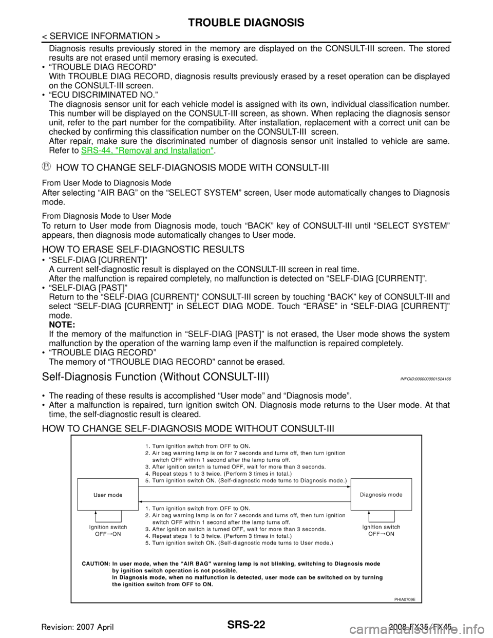
Self-Diagnosis Function (Without CONSULT-III)INFOID:0000000001524166
The reading of these results is accomplished “User mode” and “Diagnosis mode”.
After a malfunction is repaired, turn ignition switch ON. Diagnosis mode returns to the User mode. At that
time, the self-diagnostic result is cleared.
HOW TO CHANGE SELF-DIAGNOSIS MODE WITHOUT CONSULT-III
PHIA0709E
3AA93ABC3ACD3AC03ACA3AC03AC63AC53A913A773A893A873A873A8E3A773A983AC73AC93AC03AC3
3A893A873A873A8F3A773A9D3AAF3A8A3A8C3A863A9D3AAF3A8B3A8C