Page 2995 of 3924
GW-82
< SERVICE INFORMATION >
DOOR MIRROR
Wiring Diagram - MIRROR - (With El ectric Foldable Door Mirror)
INFOID:0000000001328022
TIWM1862E
3AA93ABC3ACD3AC03ACA3AC03AC63AC53A913A773A893A873A873A8E3A773A983AC73AC93AC03AC3
3A893A873A873A8F3A773A9D3AAF3A8A3A8C3A863A9D3AAF3A8B3A8C
Page 2996 of 3924
DOOR MIRRORGW-83
< SERVICE INFORMATION >
C
DE
F
G H
J
K L
M A
B
GW
N
O P
TIWM1860E
3AA93ABC3ACD3AC03ACA3AC03AC63AC53A913A773A893A873A873A8E3A773A983AC73AC93AC03AC3
3A893A873A873A8F3A773A9D3AAF3A8A3A8C3A863A9D3AAF3A8B3A8C
Page 2997 of 3924
GW-84
< SERVICE INFORMATION >
DOOR MIRROR
TIWM1863E
3AA93ABC3ACD3AC03ACA3AC03AC63AC53A913A773A893A873A873A8E3A773A983AC73AC93AC03AC3
3A893A873A873A8F3A773A9D3AAF3A8A3A8C3A863A9D3AAF3A8B3A8C
Page 2998 of 3924
DOOR MIRRORGW-85
< SERVICE INFORMATION >
C
DE
F
G H
J
K L
M A
B
GW
N
O P
TIWM1864E
3AA93ABC3ACD3AC03ACA3AC03AC63AC53A913A773A893A873A873A8E3A773A983AC73AC93AC03AC3
3A893A873A873A8F3A773A9D3AAF3A8A3A8C3A863A9D3AAF3A8B3A8C
Page 2999 of 3924
GW-86
< SERVICE INFORMATION >
DOOR MIRROR
Trouble Diagnosis
INFOID:0000000001328023
A trouble diagnosis of a automatic drive positi oner interlocking door mirror is refer to SE-12.
TIWM1861E
3AA93ABC3ACD3AC03ACA3AC03AC63AC53A913A773A893A873A873A8E3A773A983AC73AC93AC03AC3
3A893A873A873A8F3A773A9D3AAF3A8A3A8C3A863A9D3AAF3A8B3A8C
Page 3000 of 3924

DOOR MIRRORGW-87
< SERVICE INFORMATION >
C
DE
F
G H
J
K L
M A
B
GW
N
O P
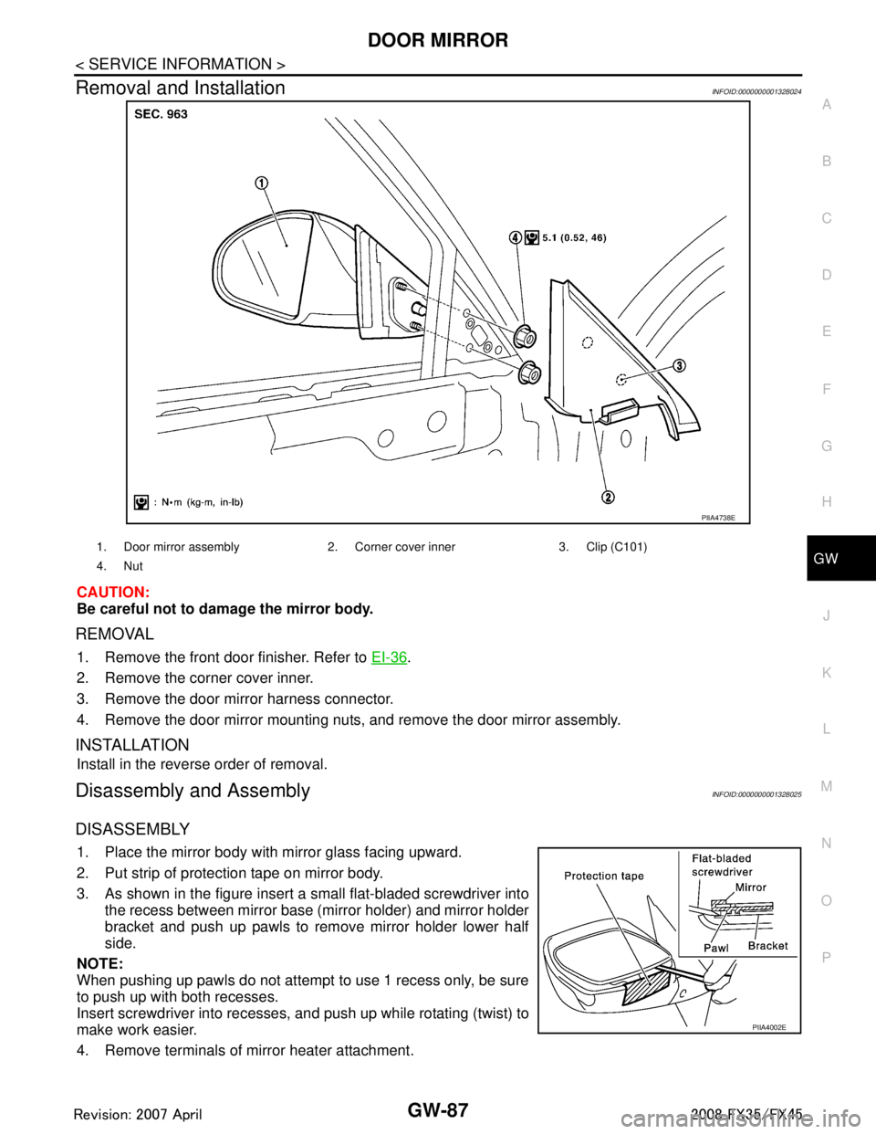
Removal and InstallationINFOID:0000000001328024
CAUTION:
Be careful not to damage the mirror body.
REMOVAL
1. Remove the front door finisher. Refer to EI-36.
2. Remove the corner cover inner.
3. Remove the door mirror harness connector.
4. Remove the door mirror mounting nuts, and remove the door mirror assembly.
INSTALLATION
Install in the reverse order of removal.
Disassembly and AssemblyINFOID:0000000001328025
DISASSEMBLY
1. Place the mirror body with mirror glass facing upward.
2. Put strip of protection tape on mirror body.
3. As shown in the figure insert a small flat-bladed screwdriver into the recess between mirror base (mirror holder) and mirror holder
bracket and push up pawls to remove mirror holder lower half
side.
NOTE:
When pushing up pawls do not attempt to use 1 recess only, be sure
to push up with both recesses.
Insert screwdriver into recesses, and push up while rotating (twist) to
make work easier.
4. Remove terminals of mirror heater attachment.
PIIA4738E
1. Door mirror assembly 2. Corn er cover inner 3. Clip (C101)
4. Nut
PIIA4002E
3AA93ABC3ACD3AC03ACA3AC03AC63AC53A913A773A893A873A873A8E3A773A983AC73AC93AC03AC3
3A893A873A873A8F3A773A9D3AAF3A8A3A8C3A863A9D3AAF3A8B3A8C
Page 3001 of 3924
GW-88
< SERVICE INFORMATION >
DOOR MIRROR
5. Lightly lift up lower side of mirror surface, and detach pawls of upper side from bracket as if pulling it out.
Remove mirror surface from mirror body.
NOTE:
Be certain not to allow grease on sealing agent in cent er of mirror body assembly (actuator) or back side of
mirror surface (mirror holder).
ASSEMBLY
1. Place mirror holder bracket and mirror body assembly (actuator) in a horizontal position.
2. Connect terminals of heater installed mirror.
3. Fit the upper pawls on the mirror face onto the mirror holder bracket first, then press the lower side of mirror face until a click
sound is heard to engage the lower pawls.
NOTE:
After installation, visually make sure lower pawls are securely
engaged from the bottom of mirror face.
PIIA4003E
3AA93ABC3ACD3AC03ACA3AC03AC63AC53A913A773A893A873A873A8E3A773A983AC73AC93AC03AC3
3A893A873A873A8F3A773A9D3AAF3A8A3A8C3A863A9D3AAF3A8B3A8C
Page 3002 of 3924

IP-1
BODY
C
DE
F
G H
J
K L
M
SECTION IP
A
B
IP
N
O P
CONTENTS
INSTRUMENT PANEL
SERVICE INFORMATION .. ..........................2
PRECAUTIONS .............................................. .....2
Precaution for Supplemental Restraint System
(SRS) "AIR BAG" and "SEAT BELT PRE-TEN-
SIONER" ............................................................. ......
2
Precaution .................................................................2
PREPARATION ...................................................3
Special Service Tool ........................................... ......3
Commercial Service Tool ..........................................3
SQUEAK AND RATTLE TROUBLE DIAG-
NOSES ...............................................................
4
Work Flow ............................................................ .....4
Generic Squeak and Rattle Troubleshooting ............6
Diagnostic Worksheet ...............................................8
INSTRUMENT PANEL ASSEMBLY .................10
Component Parts Location ......................................10
Removal and Installation .........................................11
Disassembly and Assembly .....................................16
3AA93ABC3ACD3AC03ACA3AC03AC63AC53A913A773A893A873A873A8E3A773A983AC73AC93AC03AC3
3A893A873A873A8F3A773A9D3AAF3A8A3A8C3A863A9D3AAF3A8B3A8C