2008 INFINITI FX35 engine oil
[x] Cancel search: engine oilPage 3483 of 3924
PS-28
< SERVICE INFORMATION >
POWER STEERING OIL PUMP
Before starting work, confirm belt tension is proper.
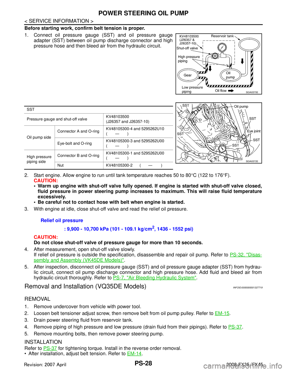
1. Connect oil pressure gauge (SST) and oil pressure gaugeadapter (SST) between oil pump discharge connector and high
pressure hose and then bleed air from the hydraulic circuit.
2. Start engine. Allow engine to run until tank temperature reaches 50 to 80 °C (122 to 176 °F).
CAUTION:
Warm up engine with shut-off val ve fully opened. If engine is started with shut-off valve closed,
fluid pressure in power steering pump increases to maximum. This will raise fluid temperature
excessively.
Be careful not to contact hose with belt when engine is started.
3. With engine at idle, close shut-off valve and read the relief oil pressure.
CAUTION:
Do not close shut-off valve of pressu re gauge for more than 10 seconds.
4. After measurement, open shut-off valve slowly. If relief oil pressure is outside the specification, disassemble and repair oil pump. Refer to PS-32, "
Disas-
sembly and Assembly (VK45DE Models)".
5. After inspection, disconnect oil pressure gauge (S ST) and oil pressure gauge adapter (SST) from hydrau-
lic circuit, connect oil pump discharge connector and high pressure hose. Add fluid and bleed air from
hydraulic circuit thoroughly. Refer to PS-7, "
Air Bleeding Hydraulic System".
Removal and Installation (VQ35DE Models)INFOID:0000000001327719
REMOVAL
1. Remove undercover from vehicle with power tool.
2. Loosen belt tensioner adjust screw, then remove belt from oil pump pulley. Refer to EM-15
.
3. Drain power steering fluid from reservoir tank.
4. Remove piping of high pressure and low pressure (drain fluid from their pipings). Refer to PS-37
.
5. Remove mounting bolts, then remove power steering pump.
INSTALLATION
Refer to PS-37 for tightening torque. Install in the reverse order removal.
After installation, adjust belt tension. Refer to EM-14
.
SGIA0570E
SST
Pressure gauge and shut-off valveKV48103500
(J26357 and J26357-10)
Oil pump side Connector A and O-ring
KV48105300-4 and 5295262U10
(—)
Eye-bolt and O-ring KV48105300-3 and 5295262U00
(—)
High pressure
piping side Connector B and O-ring
KV48105300-1 and 5295262U00
(—)
Nut KV48105300-2 ( — )
SGIA0572E
Relief oil pressure : 9,900 - 10,700 kPa (101 - 109.1 kg/cm
2, 1436 - 1552 psi)
3AA93ABC3ACD3AC03ACA3AC03AC63AC53A913A773A893A873A873A8E3A773A983AC73AC93AC03AC3
3A893A873A873A8F3A773A9D3AAF3A8A3A8C3A863A9D3AAF3A8B3A8C
Page 3484 of 3924
POWER STEERING OIL PUMPPS-29
< SERVICE INFORMATION >
C
DE
F
H I
J
K L
M A
B
PS
N
O P
After installation, bleed air. Refer to PS-7, "Air Bleeding Hydraulic System".
Removal and Installation (VK45DE Models)INFOID:0000000001327720
REMOVAL
1. Remove undercover from vehicle with power tool.
2. Remove power steering oil pump belt from auto tensioner. Refer to EM-170
.
3. Drain power steering fluid from reservoir tank.
4. Remove piping of high pressure and low pressure from power steering oil pump (drain fluid from their pip- ings). Refer to PS-37
.
5. Remove mounting bolts, then remove power steering pump.
INSTALLATION
Refer to PS-37 for tightening torque. Install in the reverse order removal.
After installation, bleed air. Refer to PS-7, "
Air Bleeding Hydraulic System".
NOTE:
Adjustment of belt tension is no necessary bec ause engine of this model equips auto tensioner.
Disassembly and Assembly (VQ35DE Models)INFOID:0000000001327721
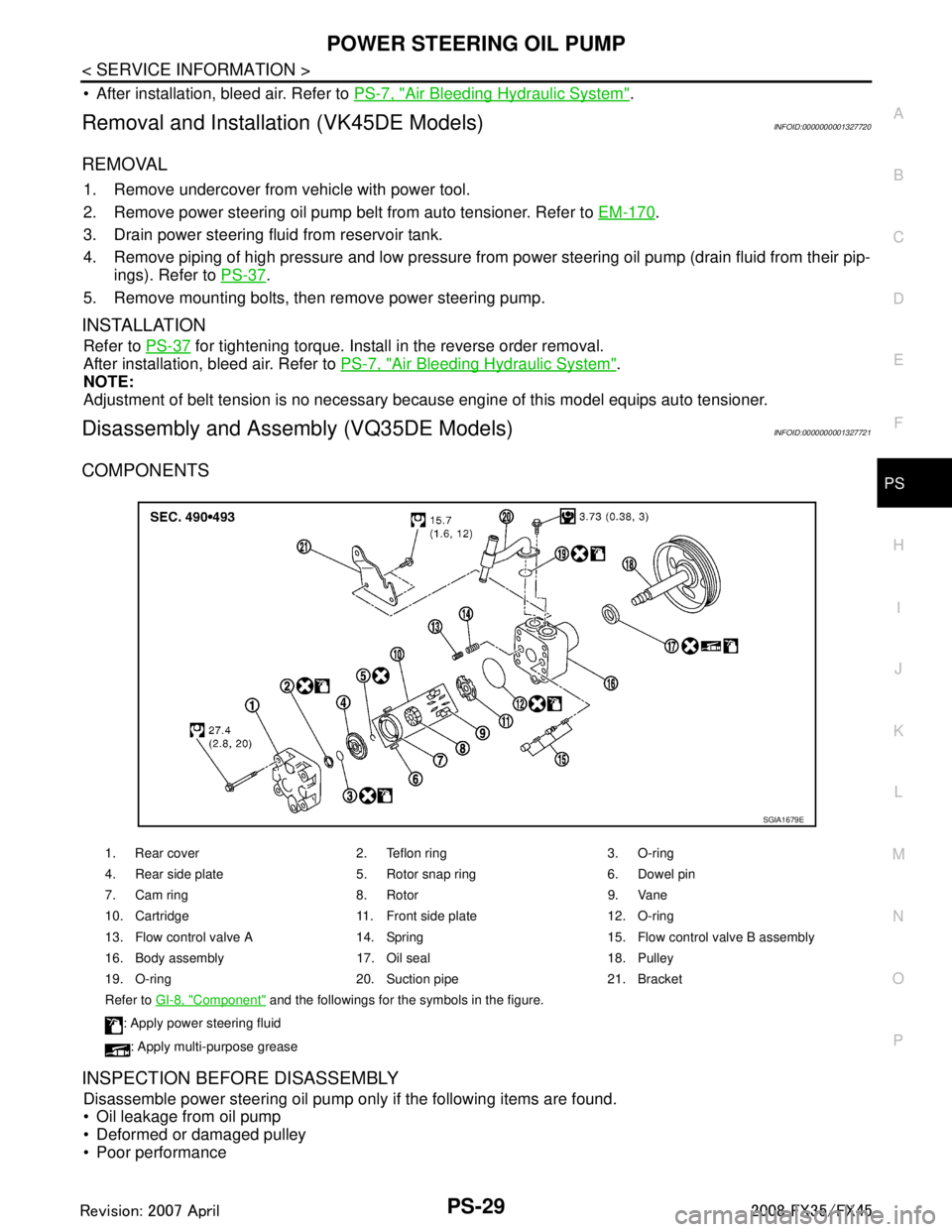
COMPONENTS
INSPECTION BEFORE DISASSEMBLY
Disassemble power steering oil pump only if the following items are found.
Oil leakage from oil pump
Deformed or damaged pulley
Poor performance
1. Rear cover 2. Teflon ring 3. O-ring
4. Rear side plate 5. Rotor snap ring 6. Dowel pin
7. Cam ring 8. Rotor 9. Vane
10. Cartridge 11. Front side plate 12. O-ring
13. Flow control valve A 14. Spring 15. Flow control valve B assembly
16. Body assembly 17. Oil seal 18. Pulley
19. O-ring 20. Suction pipe 21. Bracket
Refer to GI-8, "
Component" and the followings for the symbols in the figure.
: Apply power steering fluid
: Apply multi-purpose grease
SGIA1679E
3AA93ABC3ACD3AC03ACA3AC03AC63AC53A913A773A893A873A873A8E3A773A983AC73AC93AC03AC3
3A893A873A873A8F3A773A9D3AAF3A8A3A8C3A863A9D3AAF3A8B3A8C
Page 3551 of 3924
DIFFERENTIAL GEAR OILRFD-9
< SERVICE INFORMATION >
CEF
G H
I
J
K L
M A
B
RFD
N
O P
DIFFERENTIAL GEAR OIL
Changing Differential Gear OilINFOID:0000000001327495
DRAINING
1. Stop engine.
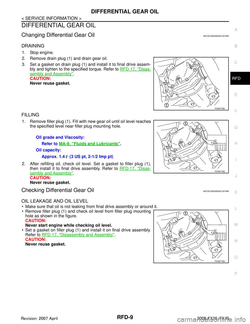
2. Remove drain plug (1) and drain gear oil.
3. Set a gasket on drain plug (1) and install it to final drive assem- bly and tighten to the specified torque. Refer to RFD-17, "
Disas-
sembly and Assembly".
CAUTION:
Never reuse gasket.
FILLING
1. Remove filler plug (1). Fill with new gear oil until oil level reaches the specified level near filler plug mounting hole.
2. After refilling oil, check oil level. Set a gasket to filler plug (1), then install it to final drive assembly. Refer to RFD-17, "
Disas-
sembly and Assembly".
CAUTION:
Never reuse gasket.
Checking Differential Gear OilINFOID:0000000001327496
OIL LEAKAGE AND OIL LEVEL
Make sure that oil is not leaking from final drive assembly or around it.
Remove filler plug (1) and check oil level from filler plug mounting hole as shown in the figure.
CAUTION:
Never start engine while checking oil level.
Set a gasket on filler plug (1) and install it on final drive assembly.
Refer to RFD-17, "
Disassembly and Assembly".
CAUTION:
Never reuse gasket.
PDIA0748J
Oil grade and Viscosity:
Refer to MA-9, "
Fluids and Lubricants".
Oil capacity:
Approx. 1.4 (3 US pt, 2-1/2 Imp pt)
PDIA0749J
PDIA0749J
3AA93ABC3ACD3AC03ACA3AC03AC63AC53A913A773A893A873A873A8E3A773A983AC73AC93AC03AC3
3A893A873A873A8F3A773A9D3AAF3A8A3A8C3A863A9D3AAF3A8B3A8C
Page 3583 of 3924
RSU-2
< SERVICE INFORMATION >
PRECAUTIONS
SERVICE INFORMATION
PRECAUTIONS
CautionsINFOID:0000000001327548
• When installing rubber bushings, final tightening must be carried out under unladen conditions with tires on
level ground. Oil will shorten the life of rubber bushings. Be sure to wipe off any spilled oil.
Unladen conditions means that fuel, engine coolant and lubricant are full. Spare tire, jack, hand tools and
mats are in designated positions.
After servicing suspension parts, be sure to check wheel alignment.
Caulking nuts are not reusable. Always use new ones w hen installing. Since new caulking nuts are pre-oiled,
tighten as they are.
3AA93ABC3ACD3AC03ACA3AC03AC63AC53A913A773A893A873A873A8E3A773A983AC73AC93AC03AC3
3A893A873A873A8F3A773A9D3AAF3A8A3A8C3A863A9D3AAF3A8B3A8C
Page 3586 of 3924
REAR SUSPENSION ASSEMBLYRSU-5
< SERVICE INFORMATION >
C
DF
G H
I
J
K L
M A
B
RSU
N
O P
REAR SUSPENSION ASSEMBLY
On-Vehicle Inspection and ServiceINFOID:0000000001327552
Make sure the mounting conditions (looseness, ba ck lash) of each component and component status (wear,
damage) are normal.
INSPECTION OF BALL JOINT END PLAY
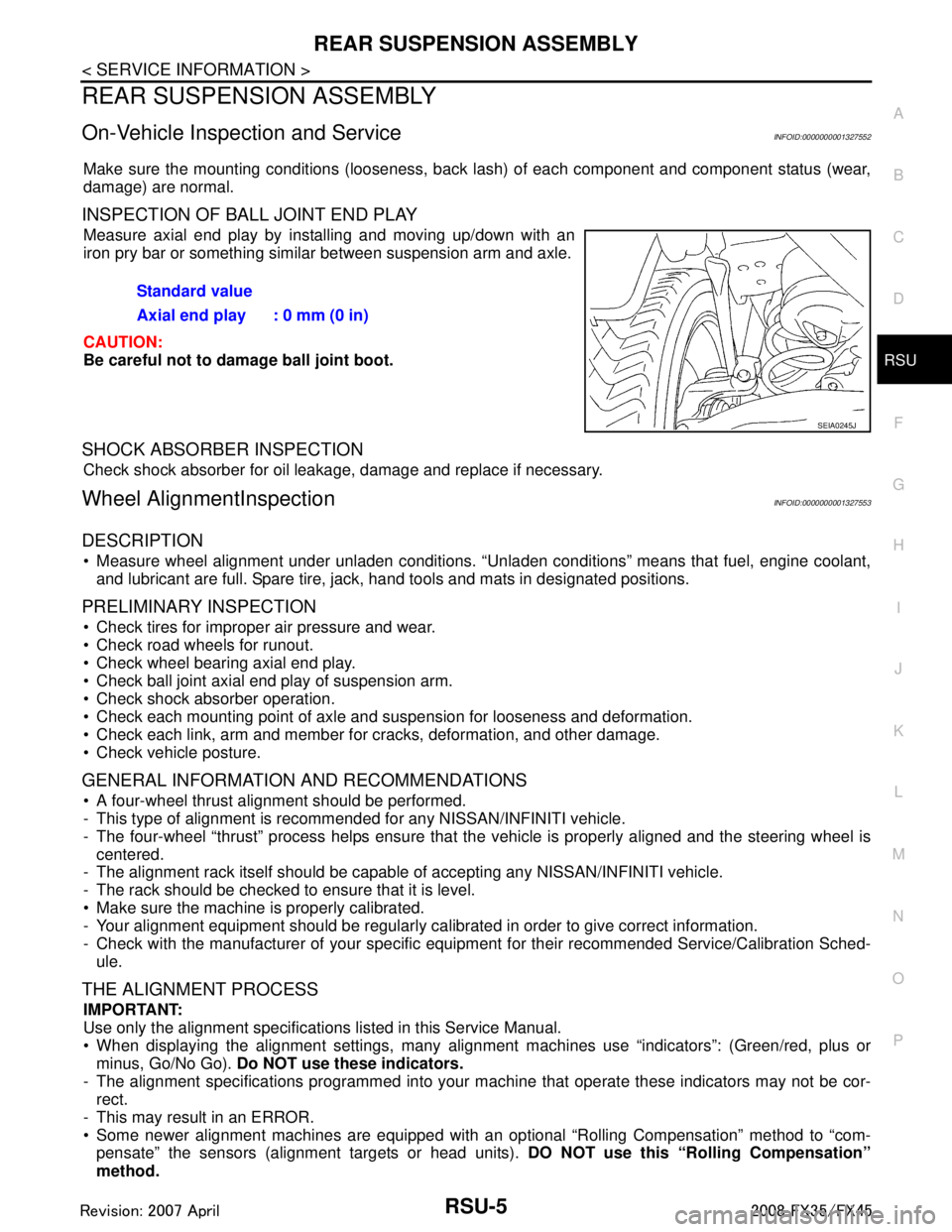
Measure axial end play by installing and moving up/down with an
iron pry bar or something similar between suspension arm and axle.
CAUTION:
Be careful not to damage ball joint boot.
SHOCK ABSORBER INSPECTION
Check shock absorber for oil leakage, damage and replace if necessary.
Wheel AlignmentInspectionINFOID:0000000001327553
DESCRIPTION
Measure wheel alignment under unladen conditions. “U nladen conditions” means that fuel, engine coolant,
and lubricant are full. Spare tire, jack, hand tools and mats in designated positions.
PRELIMINARY INSPECTION
Check tires for improper air pressure and wear.
Check road wheels for runout.
Check wheel bearing axial end play.
Check ball joint axial end play of suspension arm.
Check shock absorber operation.
Check each mounting point of axle and suspension for looseness and deformation.
Check each link, arm and member for cracks, deformation, and other damage.
Check vehicle posture.
GENERAL INFORMATION AND RECOMMENDATIONS
A four-wheel thrust alignment should be performed.
- This type of alignment is recomm ended for any NISSAN/INFINITI vehicle.
- The four-wheel “thrust” process helps ensure that t he vehicle is properly aligned and the steering wheel is
centered.
- The alignment rack itself should be capable of accepting any NISSAN/INFINITI vehicle.
- The rack should be checked to ensure that it is level.
Make sure the machine is properly calibrated.
- Your alignment equipment should be regularly ca librated in order to give correct information.
- Check with the manufacturer of your specific equi pment for their recommended Service/Calibration Sched-
ule.
THE ALIGNMENT PROCESS
IMPORTANT:
Use only the alignment specificati ons listed in this Service Manual.
When displaying the alignment settings, many alignment machines use “indicators”: (Green/red, plus or
minus, Go/No Go). Do NOT use these indicators.
- The alignment specifications programmed into your machine that operate these indicators may not be cor-
rect.
- This may result in an ERROR.
Some newer alignment machines are equipped with an optional “Rolling Compensation” method to “com-
pensate” the sensors (alignment targets or head units). DO NOT use this “Rolling Compensation”
method. Standard value
Axial end play : 0 mm (0 in)
SEIA0245J
3AA93ABC3ACD3AC03ACA3AC03AC63AC53A913A773A893A873A873A8E3A773A983AC73AC93AC03AC3
3A893A873A873A8F3A773A9D3AAF3A8A3A8C3A863A9D3AAF3A8B3A8C
Page 3599 of 3924
RSU-18
< SERVICE INFORMATION >
SERVICE DATA AND SPECIFICATIONS (SDS)
SERVICE DATA AND SPECIFICATIONS (SDS)
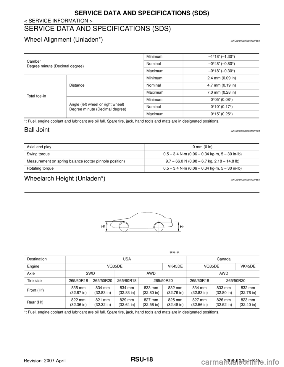
Wheel Alignment (Unladen*)INFOID:0000000001327563
*: Fuel, engine coolant and lubricant are oil full. Spare tire, jack, hand tools and mats are in designated positions.
Ball JointINFOID:0000000001327564
Wheelarch Height (Unladen*)INFOID:0000000001327565
*: Fuel, engine coolant and lubricant are oil full. Spare tire, jack, hand tools and mats are in designated positions.Camber
Degree minute (Decimal degree)
Minimum –1
°18 ′ (–1.30 °)
Nominal –0 °48 ′ (–0.80 °)
Maximum –0 °18 ′ (–0.30 °)
To t a l t o e - i n Distance
Minimum 2.4 mm (0.09 in)
Nominal 4.7 mm (0.19 in)
Maximum 7.0 mm (0.28 in)
Angle (left wheel or right wheel)
Degree minute (Decimal degree) Minimum 0
°05 ′ (0.08 °)
Nominal 0 °10 ′ (0.17 °)
Maximum 0 °15 ′ (0.25 °)
Axial end play 0 mm (0 in)
Swing torque 0.5 − 3.4 N·m (0.06 − 0.34 kg-m, 5 − 30 in-lb)
Measurement on spring balance (cotter pinhole position) 9.7 − 66.0 N (0.98 − 6.7 kg, 2.18 − 14.8 lb)
Rotating torque 0.5 − 3.4 N·m (0.06 − 0.34 kg-m, 5 − 30 in-lb)
Destination USA Canada
Engine VQ35DE VK45DE VQ35DE VK45DE
Axle 2WD AWD AWD
Tire size 265/60R18 265/50R20 265/60R18 265/50R20 265/60R18 265/50R20
Front (Hf) 835 mm
(32.87 in) 834 mm
(32.83 in) 834 mm
(32.83 in) 833 mm
(32.80 in) 832 mm
(32.76 in) 834 mm
(32.83 in) 833 mm
(32.80 in) 832 mm
(32.76 in)
Rear (Hr) 822 mm
(32.36 in) 821 mm
(32.32 in) 829 mm
(32.64 in) 827 mm
(32.56 in) 825 mm
(32.48 in) 827 mm
(32.56 in) 826 mm
(32.52 in) 823 mm
(32.40 in)
SFA818A
3AA93ABC3ACD3AC03ACA3AC03AC63AC53A913A773A893A873A873A8E3A773A983AC73AC93AC03AC3
3A893A873A873A8F3A773A9D3AAF3A8A3A8C3A863A9D3AAF3A8B3A8C
Page 3623 of 3924
SC-14
< SERVICE INFORMATION >
STARTING SYSTEM
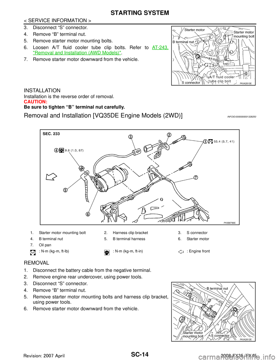
3. Disconnect “S” connector.
4. Remove “B” terminal nut.
5. Remove starter motor mounting bolts.
6. Loosen A/T fluid cooler tube clip bolts. Refer to AT-243,
"Removal and Installation (AWD Models)".
7. Remove starter motor downward from the vehicle.
INSTALLATION
Installation is the reverse order of removal.
CAUTION:
Be sure to tighten “B” terminal nut carefully.
Removal and Installation [V Q35DE Engine Models (2WD)]INFOID:0000000001328250
REMOVAL
1. Disconnect the battery cable from the negative terminal.
2. Remove engine rear undercover, using power tools.
3. Disconnect “S” connector.
4. Remove “B” terminal nut.
5. Remove starter motor mounting bolts and harness clip bracket,
using power tools.
6. Remove starter motor downward from the vehicle.
PKIA2810E
1. Starter motor mounting bolt 2. Harness clip bracket 3. S connector
4. B terminal nut 5. B termin al harness 6. Starter motor
7. Oil pan : N·m (kg-m, ft-lb) : N·m (kg-m, ft-in) : Engine front
PKIB8799E
PKIA2812E
3AA93ABC3ACD3AC03ACA3AC03AC63AC53A913A773A893A873A873A8E3A773A983AC73AC93AC03AC3
3A893A873A873A8F3A773A9D3AAF3A8A3A8C3A863A9D3AAF3A8B3A8C
Page 3624 of 3924
STARTING SYSTEMSC-15
< SERVICE INFORMATION >
C
DE
F
G H
I
J
L
M A
B
SC
N
O P
INSTALLATION
Installation is the reverse order of removal.
CAUTION:
Be sure to tighten “B” terminal nut carefully.
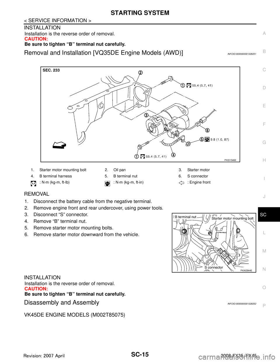
Removal and Installation [V Q35DE Engine Models (AWD)]INFOID:0000000001328251
REMOVAL
1. Disconnect the battery cabl e from the negative terminal.
2. Remove engine front and rear undercover, using power tools.
3. Disconnect “S” connector.
4. Remove “B” terminal nut.
5. Remove starter motor mounting bolts.
6. Remove starter motor downward from the vehicle.
INSTALLATION
Installation is the reverse order of removal.
CAUTION:
Be sure to tighten “B” terminal nut carefully.
Disassembly and AssemblyINFOID:0000000001328252
VK45DE ENGINE MODELS (M002T85075)
1. Starter motor mounting bolt 2. Oil pan 3. Starter motor
4. B terminal harness 5. B terminal nut 6. S connector
: N·m (kg-m, ft-lb) : N·m (k g-m, ft-in) : Engine front
PKID1546E
PKIA2844E
3AA93ABC3ACD3AC03ACA3AC03AC63AC53A913A773A893A873A873A8E3A773A983AC73AC93AC03AC3
3A893A873A873A8F3A773A9D3AAF3A8A3A8C3A863A9D3AAF3A8B3A8C