2008 INFINITI FX35 fuse box
[x] Cancel search: fuse boxPage 3365 of 3924

PG-1
ELECTRICAL
C
DE
F
G H
I
J
L
M
SECTION PG
A
B
PG
N
O P
CONTENTS
POWER SUPPLY, GROUND & CIRCUIT ELEMENTS
SERVICE INFORMATION .. ..........................2
DTC INDEX ..................................................... .....2
U1000 .................................................................. ......2
POWER SUPPLY ROUTING CIRCUIT ...............3
Schematic ........................................................... ......3
Wiring Diagram - POWER - ......................................4
Fuse ........................................................................16
Fusible Link .............................................................16
Circuit Breaker ........................................................16
IPDM E/R (INTELLIGENT POWER DISTRI-
BUTION MODULE ENGINE ROOM) .................
17
System Description ............................................. ....17
CAN Communication System Description ...............18
CAN Communication Unit .......................................18
Function of Detecting Ignition Relay Malfunction ....18
CONSULT-III Function (IPDM E/R) ..................... ....18
Auto Active Test ......................................................20
Schematic ...............................................................22
IPDM E/R Terminal Arrangement ...........................23
IPDM E/R Power/Ground Circuit Inspection ...........23
U1000 CAN COMM CIRCUIT .................................24
Removal and Installation of IPDM E/R ....................24
GROUND ...........................................................26
Ground Distribution .............................................. ....26
HARNESS .........................................................40
Harness Layout ................................................... ....40
Wiring Diagram Codes (Cell Codes) .......................60
ELECTRICAL UNITS LOCATION ....................64
Electrical Units Location ..........................................64
HARNESS CONNECTOR .................................68
Description ...............................................................68
ELECTRICAL UNITS ........................................71
Terminal Arrangement .............................................71
SMJ (SUPER MULTIPLE JUNCTION) .............73
Terminal Arrangement .............................................73
STANDARDIZED RELAY .................................75
Description ...............................................................75
FUSE BLOCK - JUNCTION BOX (J/B) ............77
Terminal Arrangement .............................................77
FUSE, FUSIBLE LINK AND RELAY BOX ........78
Terminal Arrangement .............................................78
3AA93ABC3ACD3AC03ACA3AC03AC63AC53A913A773A893A873A873A8E3A773A983AC73AC93AC03AC3
3A893A873A873A8F3A773A9D3AAF3A8A3A8C3A863A9D3AAF3A8B3A8C
Page 3381 of 3924
IPDM E/R (INTELLIGENT POWER DISTRIBUTION MODULE ENGINE ROOM)
PG-17
< SERVICE INFORMATION >
C
D E
F
G H
I
J
L
M A
B
PG
N
O P
IPDM E/R (INTELLIGENT POWER DISTRIBUTION MODULE ENGINE
ROOM)
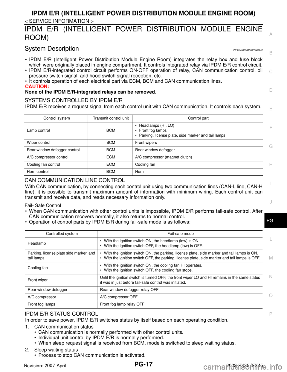
System DescriptionINFOID:0000000001328870
IPDM E/R (Intelligent Power Distribution Module Engi ne Room) integrates the relay box and fuse block
which were originally placed in engine compartment. It c ontrols integrated relay via IPDM E/R control circuit.
IPDM E/R-integrated control circuit performs ON-OFF operation of relay, CAN communication control, oil
pressure switch signal, and hood switch signal reception, etc.
It controls operation of each electrical pa rt via ECM, BCM and CAN communication lines.
CAUTION:
None of the IPDM E/R-integr ated relays can be removed.
SYSTEMS CONTROLLED BY IPDM E/R
IPDM E/R receives a request signal fr om each control unit with CAN communication. It controls each system.
CAN COMMUNICATION LINE CONTROL
With CAN communication, by connecting each control uni t using two communication lines (CAN-L line, CAN-H
line), it is possible to transmit maximum amount of in formation with minimum wiring. Each control unit can
transmit and receive data, and reads necessary information only.
Fail- Safe Control
When CAN communication with other control units is impos sible, IPDM E/R performs fail-safe control. After
CAN communication recovers normally, it also returns to normal control.
Operation of control parts by IPDM E/R during fail-safe mode is as follows:
IPDM E/R STATUS CONTROL
In order to save power, IPDM E/R switches status by itself based on each operating condition.
1. CAN communication status CAN communication is normally performed with other control units.
Individual unit control by IPDM E/R is normally performed.
When sleep request signal is received from BCM, mode is switched to sleep waiting status.
2. Sleep waiting status Process to stop CAN communication is activated.
Control system Transmit control unit Control part
Lamp control BCM Headlamps (HI, LO)
Front fog lamps
Parking, license plate, side marker and tail lamps
Wiper control BCM Front wipers
Rear window defogger control BCM Rear window defogger
A/C compressor control ECM A/C compressor (magnet clutch)
Cooling fan control ECM Cooling fan
Horn control BCM Horn
Controlled system Fail-safe mode
Headlamp With the ignition switch ON, the headlamp (low) is ON.
With the ignition switch OFF, the headlamp (low) is OFF.
Parking, license plate side marker, and
tail lamps With the ignition switch ON, the parking, license plate, side marker and tail lamps is ON.
With the ignition switch OFF, the parking, license plate, side marker and tail lamps is OFF.
Cooling fan With the ignition switch ON, the cooling fan HI operates.
With the ignition switch OFF, the cooling fan stops.
Front wiper Until the ignition switch is turned OFF, the front wiper LO and HI remains in the same status
it was in just before fail-safe control was initiated.
Rear window defogger Rear window defogger relay OFF
A/C compressor A/C compressor OFF
Front fog lamps Front fog lamp relay OFF
3AA93ABC3ACD3AC03ACA3AC03AC63AC53A913A773A893A873A873A8E3A773A983AC73AC93AC03AC3
3A893A873A873A8F3A773A9D3AAF3A8A3A8C3A863A9D3AAF3A8B3A8C
Page 3441 of 3924
FUSE BLOCK - JUNCTION BOX (J/B)PG-77
< SERVICE INFORMATION >
C
DE
F
G H
I
J
L
M A
B
PG
N
O P
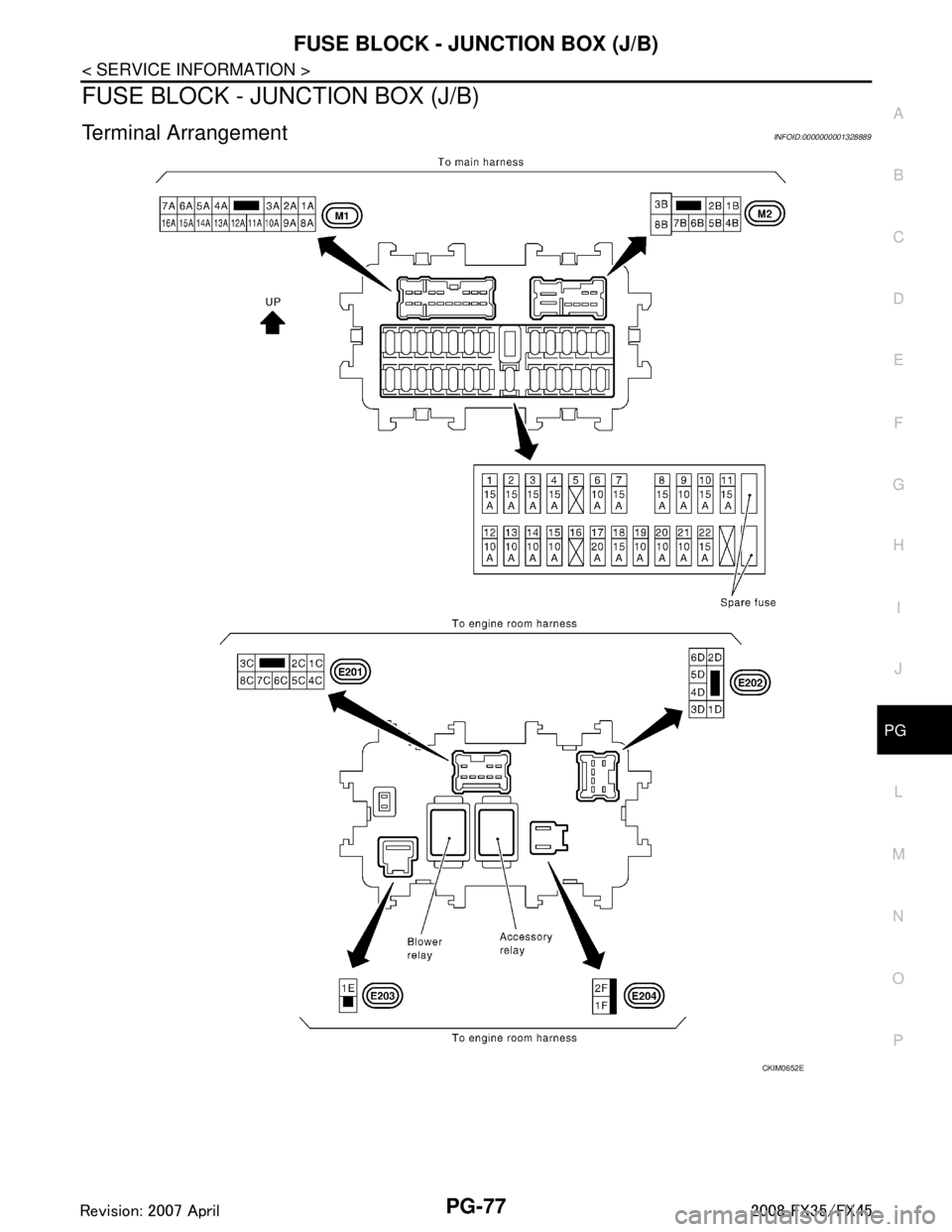
FUSE BLOCK - JUNCTION BOX (J/B)
Terminal ArrangementINFOID:0000000001328889
CKIM0652E
3AA93ABC3ACD3AC03ACA3AC03AC63AC53A913A773A893A873A873A8E3A773A983AC73AC93AC03AC3
3A893A873A873A8F3A773A9D3AAF3A8A3A8C3A863A9D3AAF3A8B3A8C
Page 3442 of 3924
PG-78
< SERVICE INFORMATION >
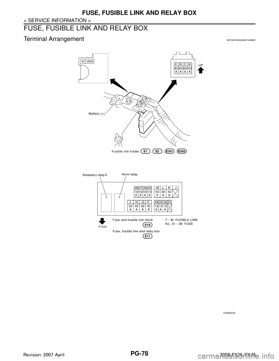
FUSE, FUSIBLE LINK AND RELAY BOX
FUSE, FUSIBLE LINK AND RELAY BOX
Terminal ArrangementINFOID:0000000001328890
CKIM0223E
3AA93ABC3ACD3AC03ACA3AC03AC63AC53A913A773A893A873A873A8E3A773A983AC73AC93AC03AC3
3A893A873A873A8F3A773A9D3AAF3A8A3A8C3A863A9D3AAF3A8B3A8C
Page 3525 of 3924
RF-10
< SERVICE INFORMATION >
SUNROOF
SUNROOF
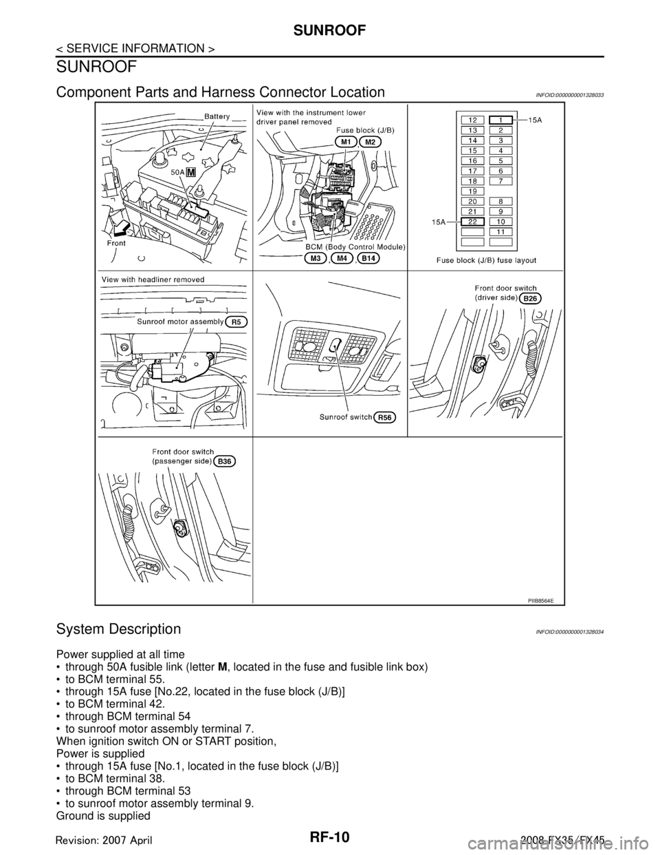
Component Parts and Harness Connector LocationINFOID:0000000001328033
System DescriptionINFOID:0000000001328034
Power supplied at all time
through 50A fusible link (letter M, located in the fuse and fusible link box)
to BCM terminal 55.
through 15A fuse [No.22, located in the fuse block (J/B)]
to BCM terminal 42.
through BCM terminal 54
to sunroof motor assembly terminal 7.
When ignition switch ON or START position,
Power is supplied
through 15A fuse [No.1, located in the fuse block (J/B)]
to BCM terminal 38.
through BCM terminal 53
to sunroof motor assembly terminal 9.
Ground is supplied
PIIB8564E
3AA93ABC3ACD3AC03ACA3AC03AC63AC53A913A773A893A873A873A8E3A773A983AC73AC93AC03AC3
3A893A873A873A8F3A773A9D3AAF3A8A3A8C3A863A9D3AAF3A8B3A8C
Page 3531 of 3924
![INFINITI FX35 2008 Service Manual
RF-16
< SERVICE INFORMATION >
SUNROOF
Check BCM Power Suppl y and Ground Circuit
INFOID:0000000001328043
1.CHECK FUSE
Check 15A fuse [No.1, located in the fuse block (J/B)]
Check 15A fuse [No.22, INFINITI FX35 2008 Service Manual
RF-16
< SERVICE INFORMATION >
SUNROOF
Check BCM Power Suppl y and Ground Circuit
INFOID:0000000001328043
1.CHECK FUSE
Check 15A fuse [No.1, located in the fuse block (J/B)]
Check 15A fuse [No.22,](/manual-img/42/57017/w960_57017-3530.png)
RF-16
< SERVICE INFORMATION >
SUNROOF
Check BCM Power Suppl y and Ground Circuit
INFOID:0000000001328043
1.CHECK FUSE
Check 15A fuse [No.1, located in the fuse block (J/B)]
Check 15A fuse [No.22, located in the fuse block (J/B)]
Check 50A fusible link (letter M, located in the fuse and fusible link box).
NOTE:
Refer to RF-10, "
Component Parts and Harness Connector Location".
OK or NG
OK >> GO TO 2.
NG >> If fuse is blown out, be sure to eliminate cause of malfunction before installing new fuse. Refer to RF-10, "
Component Parts and Harness Connector Location".
2.CHECK POWER SUPPLY CIRCUIT
1. Turn ignition switch ON.
2. Check voltage between BCM connector M3, M4 terminal 38, 42, 55 and ground.
OK or NG
OK >> GO TO 3.
NG >> Check BCM power supply circuit for open or short.
3.CHECK GROUND CIRCUIT
1. Turn ignition switch OFF.
2. Disconnect BCM connector.
3. Check continuity between BCM connector M4 terminal 49, 52 and ground.
OK or NG
OK >> Power supply and ground circuit are OK.
NG >> Check BCM ground circuit for open or short.
Check Sunroof Motor Assembly Power Supply and Ground CircuitINFOID:0000000001328044
1.CHECK POWER SUPPLY CIRCUIT
1. Turn ignition switch ON.
2. Check voltage between sunroof motor assembly connector R5 terminal 7, 9 and ground.
Retained power operation does not operate
properly. 1. Check the retained power operation mode setting.
RF-152. Check door switch.RF-19
3. Replace sunroof motor assembly.RF-22
Sunroof does not operate the interruption de-
tection function.Replace sunroof motor assembly.
RF-22
Symptom Diagnostic procedure and repair order Refer to page
38 (W/L) – Ground : Battery voltage
42 (L/R) – Ground : Battery voltage
55 (G) – Ground : Battery voltage
PIIA6160E
49 (B) – Ground : Continuity should exist.
52 (B) – Ground : Continuity should exist.
PIIA6161E
3AA93ABC3ACD3AC03ACA3AC03AC63AC53A913A773A893A873A873A8E3A773A983AC73AC93AC03AC3
3A893A873A873A8F3A773A9D3AAF3A8A3A8C3A863A9D3AAF3A8B3A8C
Page 3622 of 3924
STARTING SYSTEMSC-13
< SERVICE INFORMATION >
C
DE
F
G H
I
J
L
M A
B
SC
N
O P
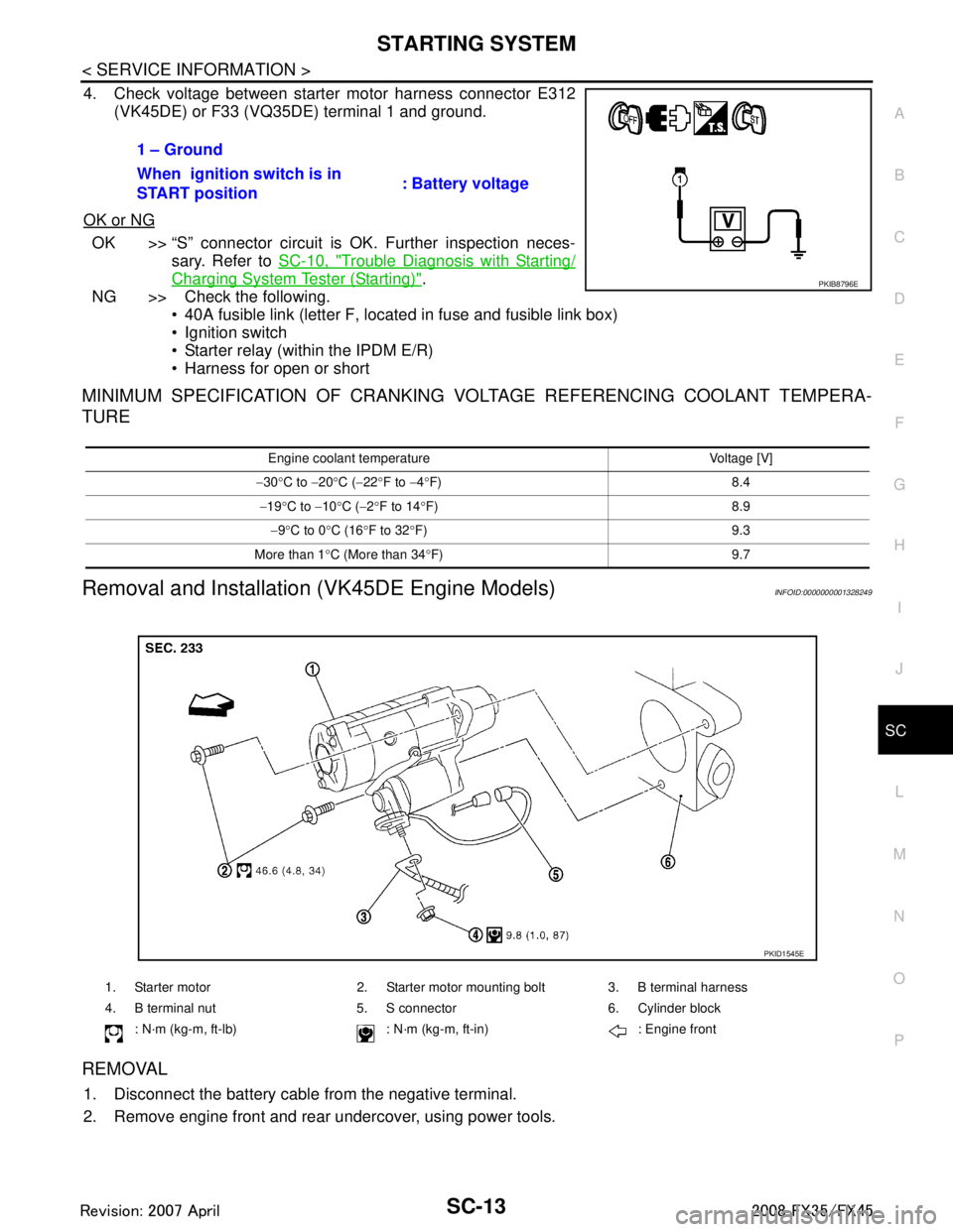
4. Check voltage between starter motor harness connector E312 (VK45DE) or F33 (VQ35DE) terminal 1 and ground.
OK or NG
OK >> “S” connector circuit is OK. Further inspection neces- sary. Refer to SC-10, "
Trouble Diagnosis with Starting/
Charging System Tester (Starting)".
NG >> Check the following.
40A fusible link (letter F, located in fuse and fusible link box)
Ignition switch
Starter relay (within the IPDM E/R)
Harness for open or short
MINIMUM SPECIFICATION OF CRANKING VO LTAGE REFERENCING COOLANT TEMPERA-
TURE
Removal and Installation (VK45DE Engine Models)INFOID:0000000001328249
REMOVAL
1. Disconnect the battery cable from the negative terminal.
2. Remove engine front and rear undercover, using power tools. 1 – Ground
When ignition switch is in
START position
: Battery voltage
PKIB8796E
Engine coolant temperature Voltage [V]
− 30 °C to −20 °C ( −22 °F to −4 °F) 8.4
− 19 °C to −10 °C ( −2 °F to 14 °F) 8.9
− 9 °C to 0 °C (16 °F to 32 °F) 9.3
More than 1 °C (More than 34 °F) 9.7
1. Starter motor 2. Starter motor mounting bolt 3. B terminal harness
4. B terminal nut 5. S connector 6. Cylinder block
: N·m (kg-m, ft-lb) : N·m (k g-m, ft-in) : Engine front
PKID1545E
3AA93ABC3ACD3AC03ACA3AC03AC63AC53A913A773A893A873A873A8E3A773A983AC73AC93AC03AC3
3A893A873A873A8F3A773A9D3AAF3A8A3A8C3A863A9D3AAF3A8B3A8C
Page 3677 of 3924
SE-38
< SERVICE INFORMATION >
AUTOMATIC DRIVE POSITIONER
NOTE:
After the setting is registered, the new setting is effective, even if the battery is disconnected.
CHECK POWER SUPPLY AND GROUND
1.CHECK FUSE
Check if any of the following fuses in the BCM are blown.
Check 50A fusible link (letter M, located in the fuse and fusible link box.)
Check 15A fuse [No.22, located in the fuse block (J/B)]
Check 10A fuse [No.1, located in the fuse block (J/B)]
Check 10A fuse [No.6, located in the fuse block (J/B)]
NOTE:
Refer to SE-16, "
Component Parts and Harness Connector Location".
OK or NG
OK >> GO TO 2.
NG >> If fuse is blown out, be sure to eliminate cause of malfunction before installing new fuse. Refer to SE-16, "
Component Parts and Harness Connector Location".
2.CHECK POWER SUPPLY CIRCUIT (BCM)
1. Turn ignition switch OFF.
2. Disconnect BCM connector.
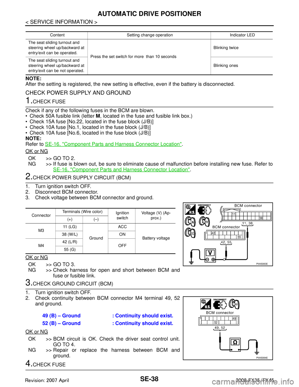
3. Check voltage between BCM connector and ground.
OK or NG
OK >> GO TO 3.
NG >> Check harness for open and short between BCM and fuse or fusible link.
3.CHECK GROUND CIRCUIT (BCM)
1. Turn ignition switch OFF.
2. Check continuity between BCM connector M4 terminal 49, 52 and ground.
OK or NG
OK >> BCM circuit is OK. Check the driver seat control unit. GO TO 4.
NG >> Repair or replace the harness between BCM and ground.
4.CHECK FUSE
Content Setting change operation Indicator LED
The seat sliding turnout and
steering wheel up/backward at
entry/exit can be operated. Press the set switch for more than 10 seconds Blinking twice
The seat sliding turnout and
steering wheel up/backward at
entry/exit can be not operated. Blinking ones
Connector
Terminals (Wire color)
Ignition
switch Voltage (V) (Ap-
prox.)
(+) (–)
M3 11 ( L G )
Ground ACC
Battery voltage
38 (W/L) ON
M4 42 (L/R)
OFF
55 (G)
PIIA5083E
49 (B) – Ground : Continuity should exist.
52 (B) – Ground : Continuity should exist.
PIIA5084E
3AA93ABC3ACD3AC03ACA3AC03AC63AC53A913A773A893A873A873A8E3A773A983AC73AC93AC03AC3
3A893A873A873A8F3A773A9D3AAF3A8A3A8C3A863A9D3AAF3A8B3A8C