2008 INFINITI FX35 fuse box
[x] Cancel search: fuse boxPage 2973 of 3924
GW-60
< SERVICE INFORMATION >
REAR WINDOW DEFOGGER
REAR WINDOW DEFOGGER
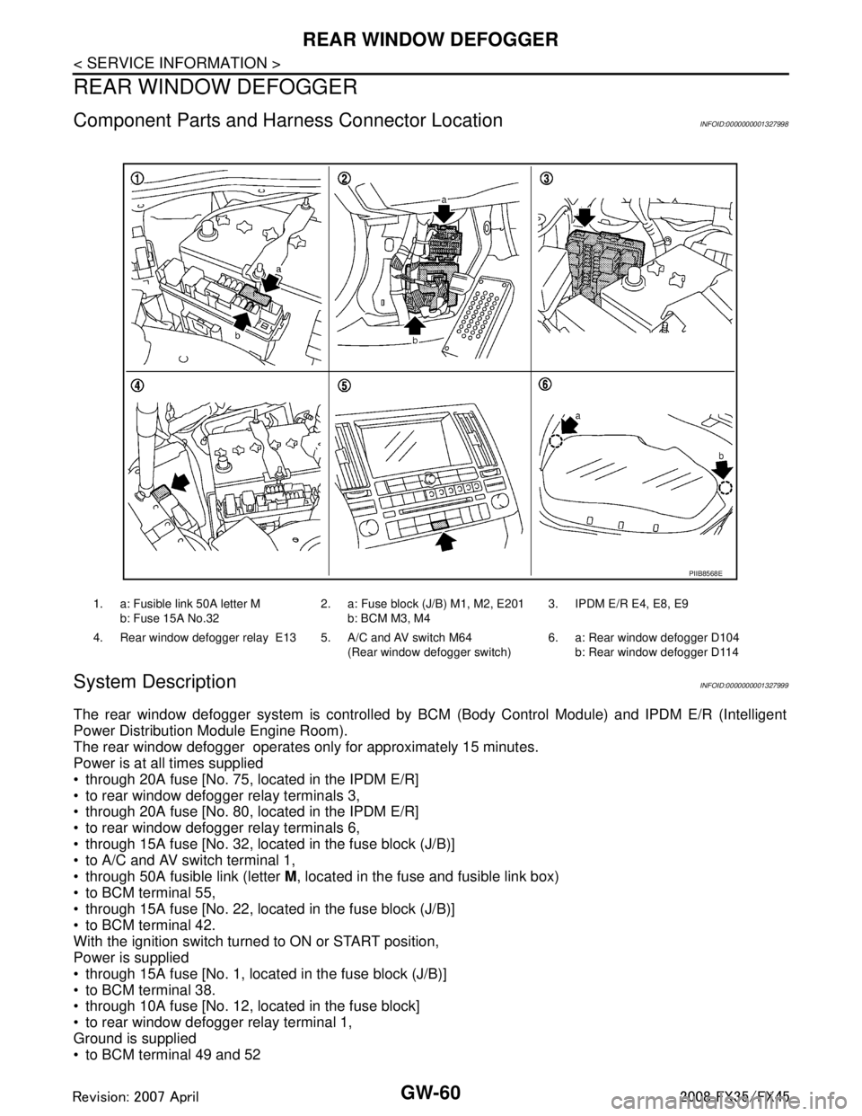
Component Parts and Harness Connector LocationINFOID:0000000001327998
System DescriptionINFOID:0000000001327999
The rear window defogger system is controlled by BC M (Body Control Module) and IPDM E/R (Intelligent
Power Distribution Module Engine Room).
The rear window defogger operates only for approximately 15 minutes.
Power is at all times supplied
through 20A fuse [No. 75, located in the IPDM E/R]
to rear window defogger relay terminals 3,
through 20A fuse [No. 80, located in the IPDM E/R]
to rear window defogger relay terminals 6,
through 15A fuse [No. 32, located in the fuse block (J/B)]
to A/C and AV switch terminal 1,
through 50A fusible link (letter M, located in the fuse and fusible link box)
to BCM terminal 55,
through 15A fuse [No. 22, located in the fuse block (J/B)]
to BCM terminal 42.
With the ignition switch turned to ON or START position,
Power is supplied
through 15A fuse [No. 1, located in the fuse block (J/B)]
to BCM terminal 38.
through 10A fuse [No. 12, located in the fuse block]
to rear window defogger relay terminal 1,
Ground is supplied
to BCM terminal 49 and 52
1. a: Fusible link 50A letter M
b: Fuse 15A No.32 2. a: Fuse block (J/B) M1, M2, E201
b: BCM M3, M4 3. IPDM E/R E4, E8, E9
4. Rear window defogger relay E13 5. A/C and AV switch M64 (Rear window defogger switch)6. a: Rear window defogger D104
b: Rear window defogger D114
PIIB8568E
3AA93ABC3ACD3AC03ACA3AC03AC63AC53A913A773A893A873A873A8E3A773A983AC73AC93AC03AC3
3A893A873A873A8F3A773A9D3AAF3A8A3A8C3A863A9D3AAF3A8B3A8C
Page 2982 of 3924
REAR WINDOW DEFOGGERGW-69
< SERVICE INFORMATION >
C
DE
F
G H
J
K L
M A
B
GW
N
O P
Check BCM Power Supply and Ground CircuitINFOID:0000000001328010
First perform the “SELF-DIAG RESULTS” in “BCM” with CONSULT-III, when perform the each trouble
diagnosis. Refer to BCS-13, "
U1000 CAN Communication Circuit".
1.CHECK FUSE
Check 15A fuse [No.1, located in the fuse block (J/B)]
Check 15A fuse [No.22, located in the fuse block (J/B)]
Check 50A fusible link (letter M located in the fuse and fusible link box).
NOTE:
Refer to GW-60, "
Component Parts and Harness Connector Location".
OK or NG
OK >> GO TO 2.
NG >> If fuse is blown out, be sure to eliminate c ause of malfunction before installing new fuse. Refer to
PG-3
.
2.CHECK POWER SUPPLY CIRCUIT
1. Turn ignition switch ON.
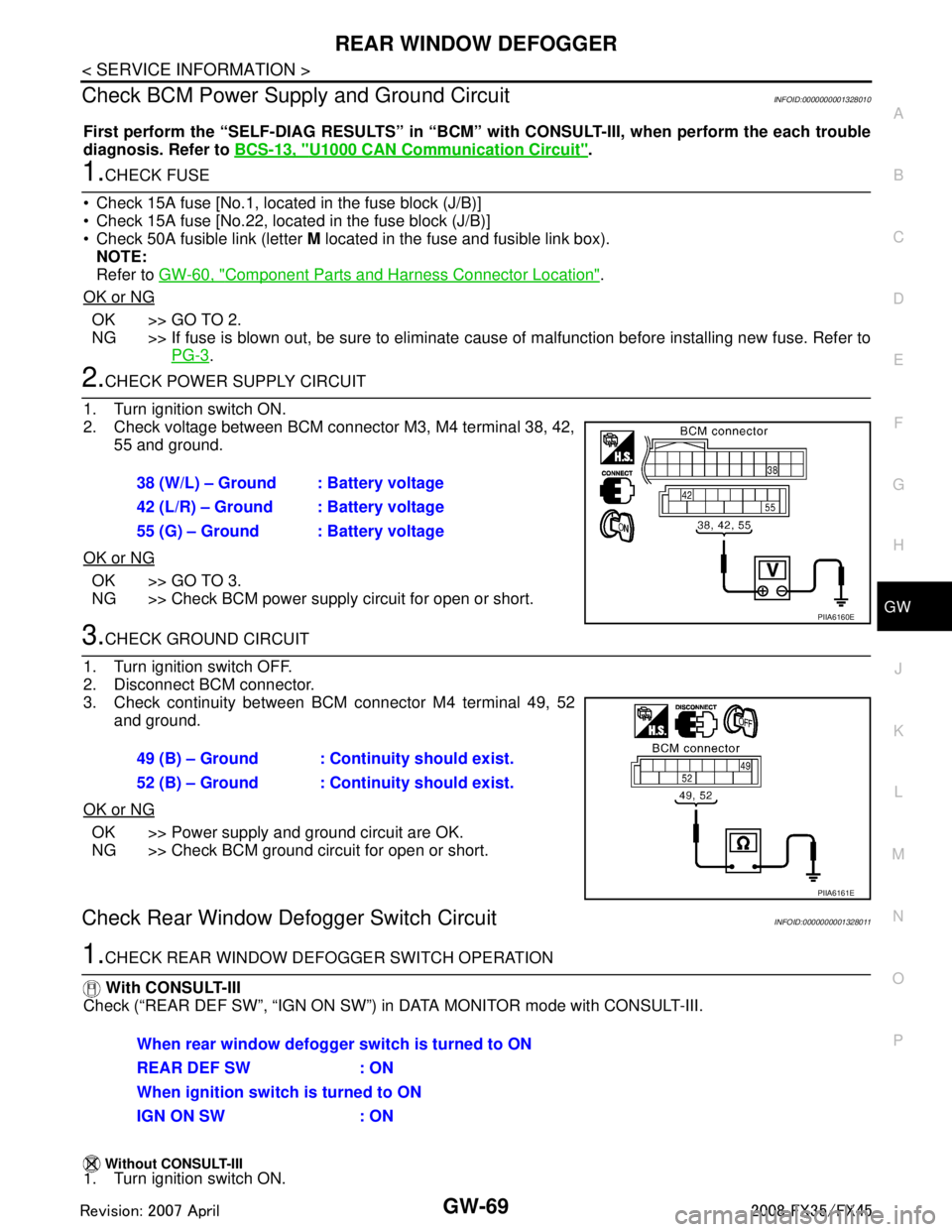
2. Check voltage between BCM connector M3, M4 terminal 38, 42, 55 and ground.
OK or NG
OK >> GO TO 3.
NG >> Check BCM power supply circuit for open or short.
3.CHECK GROUND CIRCUIT
1. Turn ignition switch OFF.
2. Disconnect BCM connector.
3. Check continuity between BCM connector M4 terminal 49, 52 and ground.
OK or NG
OK >> Power supply and ground circuit are OK.
NG >> Check BCM ground circuit for open or short.
Check Rear Window Defogger Switch CircuitINFOID:0000000001328011
1.CHECK REAR WINDOW DEF OGGER SWITCH OPERATION
With CONSULT-III
Check (“REAR DEF SW”, “IGN ON SW”) in DATA MONITOR mode with CONSULT-III.
Without CONSULT-III1. Turn ignition switch ON. 38 (W/L) – Ground : Battery voltage
42 (L/R) – Ground : Battery voltage
55 (G) – Ground : Battery voltage
PIIA6160E
49 (B) – Ground : Continuity should exist.
52 (B) – Ground : Continuity should exist.
PIIA6161E
When rear window defogger switch is turned to ON
REAR DEF SW : ON
When ignition switch is turned to ON
IGN ON SW : ON
3AA93ABC3ACD3AC03ACA3AC03AC63AC53A913A773A893A873A873A8E3A773A983AC73AC93AC03AC3
3A893A873A873A8F3A773A9D3AAF3A8A3A8C3A863A9D3AAF3A8B3A8C
Page 3107 of 3924
HEADLAMP - XENON TYPE -LT-5
< SERVICE INFORMATION >
C
DE
F
G H
I
J
L
M A
B
LT
N
O P
HEADLAMP - XENON TYPE -
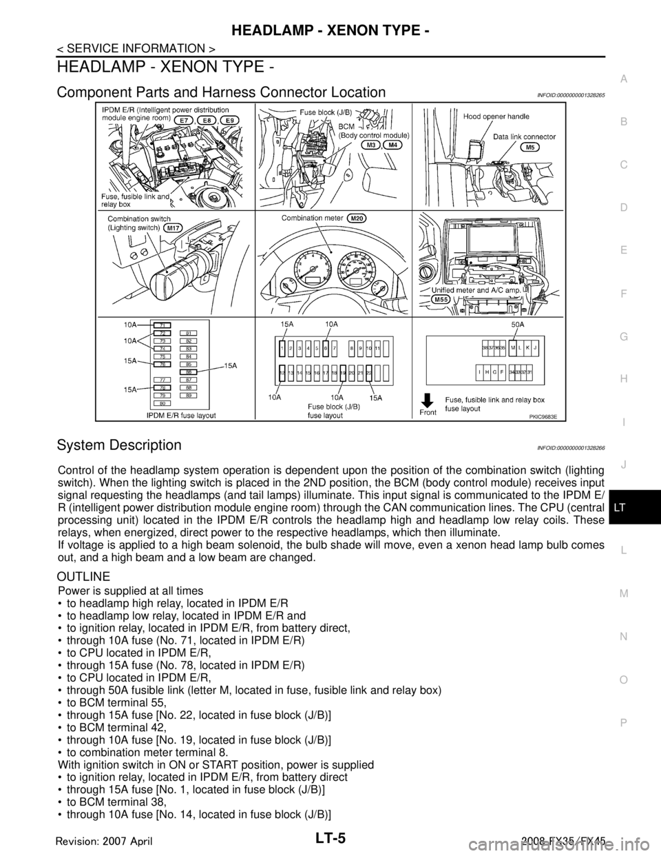
Component Parts and Har ness Connector LocationINFOID:0000000001328265
System DescriptionINFOID:0000000001328266
Control of the headlamp system operation is dependent upon t he position of the combination switch (lighting
switch). When the lighting switch is placed in the 2ND position, the BCM (body control module) receives input
signal requesting the headlamps (and tail lamps) illuminate. This input signal is communicated to the IPDM E/
R (intelligent power distribution module engine room) through the CAN communication lines. The CPU (central
processing unit) located in the IPDM E/R contro ls the headlamp high and headlamp low relay coils. These
relays, when energized, direct power to the respective headlamps, which then illuminate.
If voltage is applied to a high beam solenoid, the bulb shade will move, even a xenon head lamp bulb comes
out, and a high beam and a low beam are changed.
OUTLINE
Power is supplied at all times
to headlamp high relay, located in IPDM E/R
to headlamp low relay, located in IPDM E/R and
to ignition relay, located in IPDM E/R, from battery direct,
through 10A fuse (No. 71, located in IPDM E/R)
to CPU located in IPDM E/R,
through 15A fuse (No. 78, located in IPDM E/R)
to CPU located in IPDM E/R,
through 50A fusible link (letter M, located in fuse, fusible link and relay box)
to BCM terminal 55,
through 15A fuse [No. 22, located in fuse block (J/B)]
to BCM terminal 42,
through 10A fuse [No. 19, located in fuse block (J/B)]
to combination meter terminal 8.
With ignition switch in ON or START position, power is supplied
to ignition relay, located in IPDM E/R, from battery direct
through 15A fuse [No. 1, located in fuse block (J/B)]
to BCM terminal 38,
through 10A fuse [No. 14, located in fuse block (J/B)]
PKIC9683E
3AA93ABC3ACD3AC03ACA3AC03AC63AC53A913A773A893A873A873A8E3A773A983AC73AC93AC03AC3
3A893A873A873A8F3A773A9D3AAF3A8A3A8C3A863A9D3AAF3A8B3A8C
Page 3134 of 3924
LT-32
< SERVICE INFORMATION >
DAYTIME LIGHT SYSTEM
DAYTIME LIGHT SYSTEM
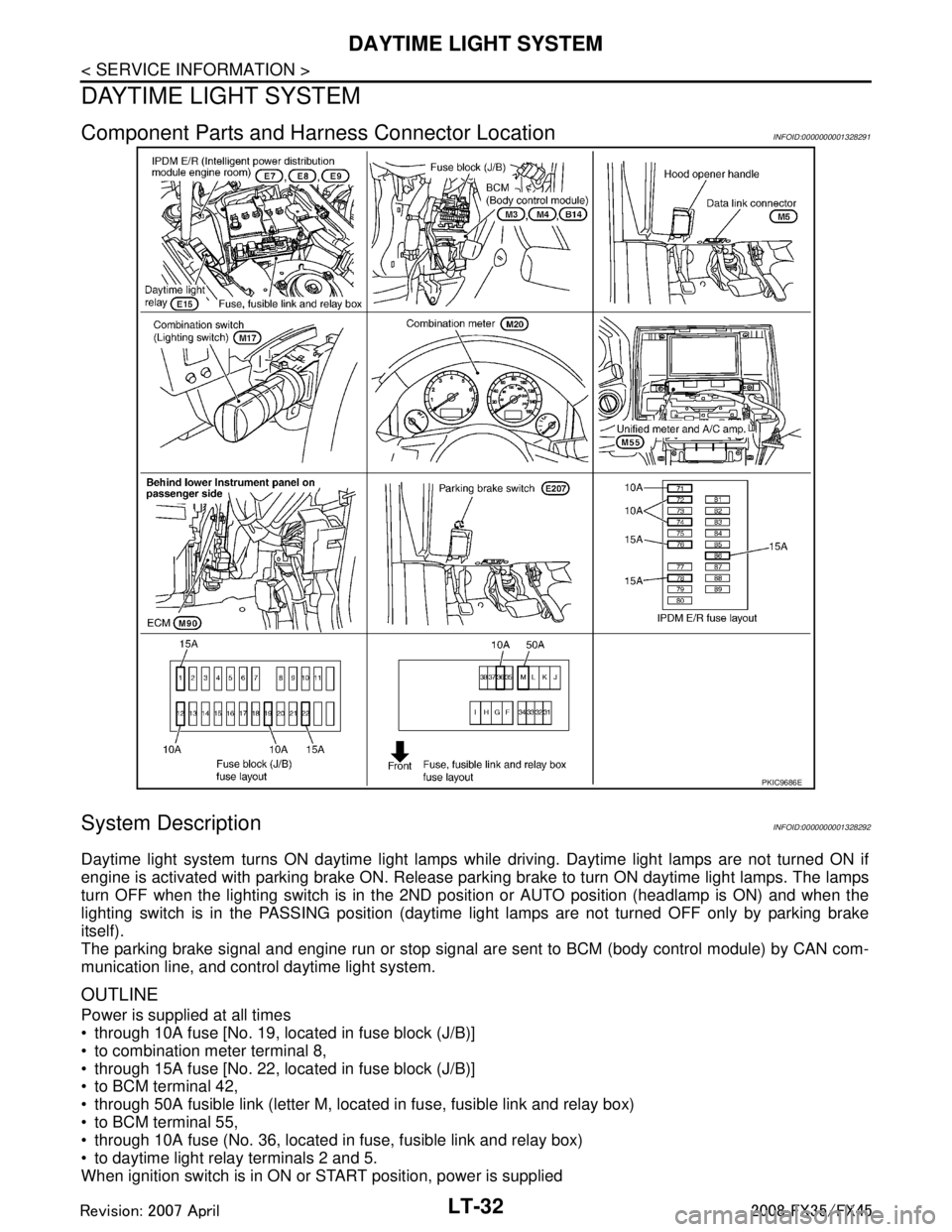
Component Parts and Harness Connector LocationINFOID:0000000001328291
System DescriptionINFOID:0000000001328292
Daytime light system turns ON daytime light lamps while driving. Daytime light lamps are not turned ON if
engine is activated with parking brake ON. Release parki ng brake to turn ON daytime light lamps. The lamps
turn OFF when the lighting switch is in the 2ND pos ition or AUTO position (headlamp is ON) and when the
lighting switch is in the PASSING position (daytime light lamps are not turned OFF only by parking brake
itself).
The parking brake signal and engine run or stop signal ar e sent to BCM (body control module) by CAN com-
munication line, and control daytime light system.
OUTLINE
Power is supplied at all times
through 10A fuse [No. 19, located in fuse block (J/B)]
to combination meter terminal 8,
through 15A fuse [No. 22, located in fuse block (J/B)]
to BCM terminal 42,
through 50A fusible link (letter M, located in fuse, fusible link and relay box)
to BCM terminal 55,
through 10A fuse (No. 36, located in fuse, fusible link and relay box)
to daytime light relay terminals 2 and 5.
When ignition switch is in ON or START position, power is supplied
PKIC9686E
3AA93ABC3ACD3AC03ACA3AC03AC63AC53A913A773A893A873A873A8E3A773A983AC73AC93AC03AC3
3A893A873A873A8F3A773A9D3AAF3A8A3A8C3A863A9D3AAF3A8B3A8C
Page 3168 of 3924
LT-66
< SERVICE INFORMATION >
FRONT FOG LAMP
FRONT FOG LAMP
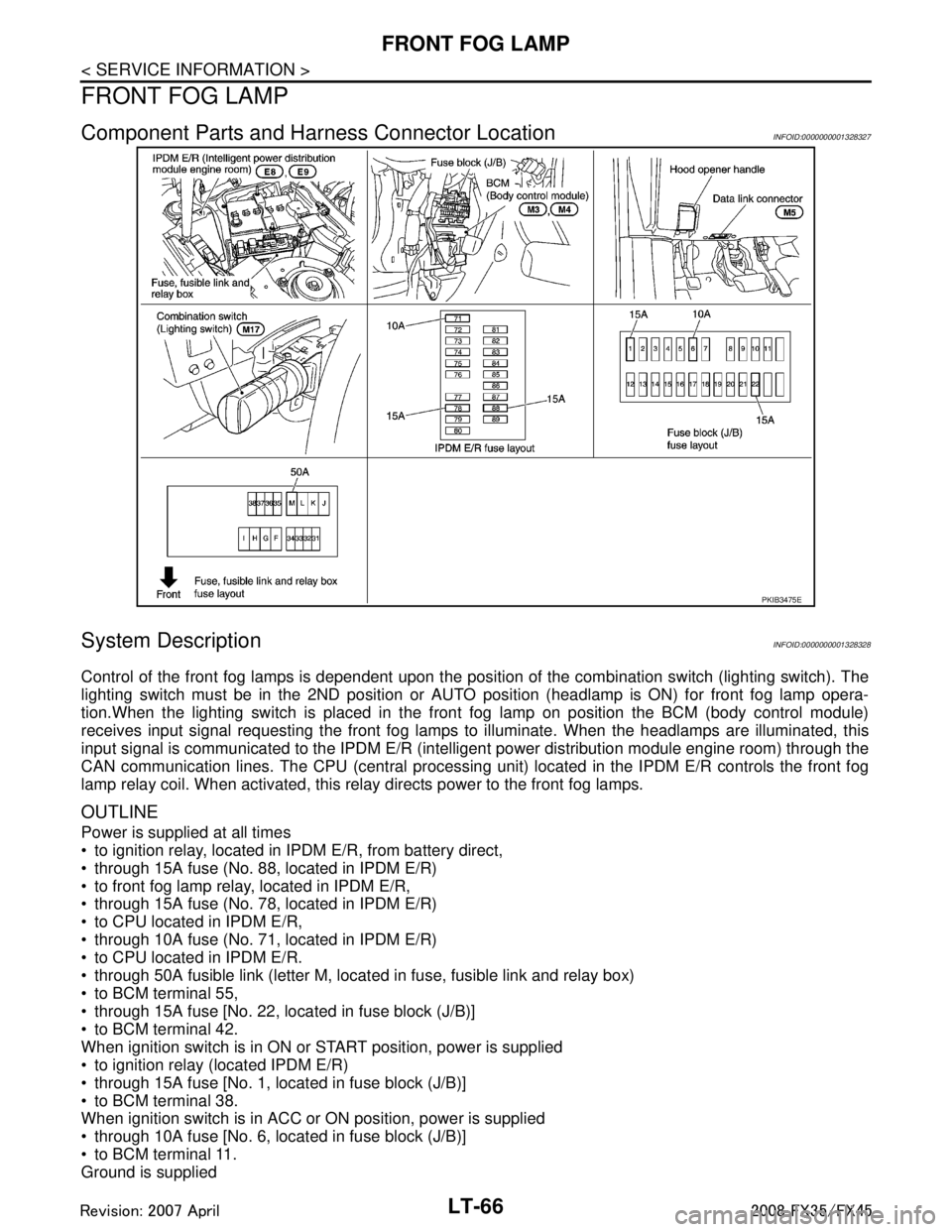
Component Parts and Harness Connector LocationINFOID:0000000001328327
System DescriptionINFOID:0000000001328328
Control of the front fog lamps is dependent upon the position of the combination switch (lighting switch). The
lighting switch must be in the 2ND position or AUTO position (headlamp is ON) for front fog lamp opera-
tion.When the lighting switch is placed in the front fog lamp on position the BCM (body control module)
receives input signal requesting the front fog lamps to illuminate. When the headlamps are illuminated, this
input signal is communicated to the IPDM E/R (inte lligent power distribution module engine room) through the
CAN communication lines. The CPU (central processing unit) located in the IPDM E/R controls the front fog
lamp relay coil. When activated, this relay directs power to the front fog lamps.
OUTLINE
Power is supplied at all times
to ignition relay, located in IP DM E/R, from battery direct,
through 15A fuse (No. 88, located in IPDM E/R)
to front fog lamp relay, located in IPDM E/R,
through 15A fuse (No. 78, located in IPDM E/R)
to CPU located in IPDM E/R,
through 10A fuse (No. 71, located in IPDM E/R)
to CPU located in IPDM E/R.
through 50A fusible link (letter M, located in fuse, fusible link and relay box)
to BCM terminal 55,
through 15A fuse [No. 22, located in fuse block (J/B)]
to BCM terminal 42.
When ignition switch is in ON or START position, power is supplied
to ignition relay (located IPDM E/R)
through 15A fuse [No. 1, located in fuse block (J/B)]
to BCM terminal 38.
When ignition switch is in ACC or ON position, power is supplied
through 10A fuse [No. 6, located in fuse block (J/B)]
to BCM terminal 11.
Ground is supplied
PKIB3475E
3AA93ABC3ACD3AC03ACA3AC03AC63AC53A913A773A893A873A873A8E3A773A983AC73AC93AC03AC3
3A893A873A873A8F3A773A9D3AAF3A8A3A8C3A863A9D3AAF3A8B3A8C
Page 3220 of 3924
LT-118
< SERVICE INFORMATION >
PARKING, LICENSE PLATE AND TAIL LAMPS
PARKING, LICENSE PLATE AND TAIL LAMPS
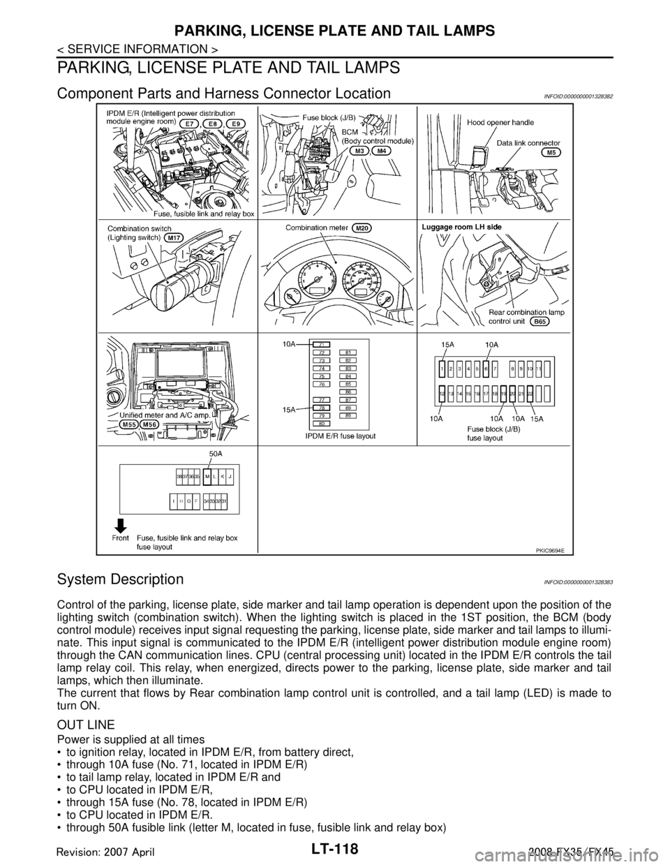
Component Parts and Harness Connector LocationINFOID:0000000001328382
System DescriptionINFOID:0000000001328383
Control of the parking, license plate, side marker and tail lamp operation is dependent upon the position of the
lighting switch (combination switch). When the lighting switch is placed in the 1ST position, the BCM (body
control module) receives input signal requesting the parki ng, license plate, side marker and tail lamps to illumi-
nate. This input signal is communicated to the IPDM E/R (intelligent power distribution module engine room)
through the CAN communication lines. CPU (central processi ng unit) located in the IPDM E/R controls the tail
lamp relay coil. This relay, when energized, directs pow er to the parking, license plate, side marker and tail
lamps, which then illuminate.
The current that flows by Rear combination lamp cont rol unit is controlled, and a tail lamp (LED) is made to
turn ON.
OUT LINE
Power is supplied at all times
to ignition relay, located in IP DM E/R, from battery direct,
through 10A fuse (No. 71, located in IPDM E/R)
to tail lamp relay, located in IPDM E/R and
to CPU located in IPDM E/R,
through 15A fuse (No. 78, located in IPDM E/R)
to CPU located in IPDM E/R.
through 50A fusible link (letter M, located in fuse, fusible link and relay box)
PKIC9694E
3AA93ABC3ACD3AC03ACA3AC03AC63AC53A913A773A893A873A873A8E3A773A983AC73AC93AC03AC3
3A893A873A873A8F3A773A9D3AAF3A8A3A8C3A863A9D3AAF3A8B3A8C
Page 3241 of 3924

INTERIOR ROOM LAMPLT-139
< SERVICE INFORMATION >
C
DE
F
G H
I
J
L
M A
B
LT
N
O P
Ignition keyhole illumination turns ON at time when dr iver door is opened (door switch ON) or removed keyfob
from key cylinder. Illumination turns OFF when driver door is closed (door switch OFF).
Step lamp turns ON at time when driver door or pa ssenger door is opened (door switch ON). Lamp turns OFF
when the driver, passenger doors are closed (all door switches OFF).
POWER SUPPLY AND GROUND
Power is supplied at all times (without Intelligent Key system)
through 15A fuse [No. 22, located in fuse block (J/B)]
to key switch terminal 2 and
to BCM terminal 42,
through 50A fusible link (letter M, located in fuse, fusible link and relay box)
to BCM terminal 55,
through 10A fuse [No. 19, located in fuse block (J/B)]
to combination meter terminal 8.
Power is supplied at all times (with Intelligent Key system)
through 10A fuse (No.38, located in fuse, fusible link and relay box)
to key switch and ignition knob switch terminal 1,
through 15A fuse [No.22, located in fuse block (J/B)]
to BCM terminal 42 and
to key switch and ignition knob switch terminal 3,
through 50A fusible link (letter M, located in fuse, fusible link and relay box)
to BCM terminal 55,
through 10A fuse [No. 19, located in fuse block (J/B)]
to combination meter terminal 8.
When key plate inserted to key switch, power is supplied (without Intelligent Key system)
through key switch terminal 1
to BCM terminal 37.
When inserted key plate to key switch, power is supplied (with Intelligent Key system)
through key switch and ignition knob switch terminal 4
to BCM terminal 37.
When moved ignition knob switch, power is supplied (with Intelligent Key system)
through ignition knob switch terminal 2
to intelligent key unit terminal 27.
With ignition switch in the ON or START position, power is supplied
through 15A fuse [No. 1, located in fuse block (J/B)]
to BCM terminal 38,
through 10A fuse [No. 14, located in fuse block (J/B)]
to combination meter terminal 7.
Ground is supplied
to BCM terminals 49 and 52, and
to combination meter terminal 5, 6 and 15
through grounds terminals M35, M45 and M85.
When driver side door is opened, ground is supplied
to BCM terminal 62
through front door switch (driver side) terminal 1
through case ground of front door switch (driver side).
When passenger side door is opened, ground is supplied
to BCM terminal 12
through front door switch (passenger side) terminal 1
through case ground of front door switch (passenger side).
When rear door RH is opened, ground is supplied
to BCM terminal 13, and
to personal lamp RH terminal 1
through rear door switch RH terminal 1
through case ground of rear door switch RH.
When rear door LH is opened, ground is supplied
to BCM terminal 63, and
to personal lamp LH terminal 1
through rear door switch LH terminal 1
through case ground of rear door switch LH.
When driver side door is unlocked by door lock and unlock switch, BCM receives a ground signal
through grounds terminals M35, M45 and M85
3AA93ABC3ACD3AC03ACA3AC03AC63AC53A913A773A893A873A873A8E3A773A983AC73AC93AC03AC3
3A893A873A873A8F3A773A9D3AAF3A8A3A8C3A863A9D3AAF3A8B3A8C
Page 3271 of 3924

ILLUMINATIONLT-169
< SERVICE INFORMATION >
C
DE
F
G H
I
J
L
M A
B
LT
N
O P
ILLUMINATION
System DescriptionINFOID:0000000001328422
Control of illumination lamps operation is dependent upon position of lighting switch (combination switch).
When lighting switch is placed in the 1ST or 2ND positi on (or if auto light system is activated), BCM (body con-
trol module) receives input signal requesting illuminati on lamps to illuminate. This input signal is communi-
cated to IPDM E/R (intelligent power distribution module engine room) through the CAN communication. The
CPU (central processing unit) located in the IPDM E/R co ntrols tail lamp relay coil. This relay, when energized,
directs power to illumination lamps, which then illuminate.
Power is supplied at all times
through 10A fuse (No. 71, located in IPDM E/R)
to tail lamp relay, located in IPDM E/R, and
to CPU located in IPDM E/R.
Power is also supplied at all times
through 50A fusible link (letter M, located in fuse, fusible link and relay box)
to BCM terminal 55,
through 15A fuse [No. 22 located in fuse block (J/B)]
to BCM terminal 42,
through 15A fuse (No. 78, located in IPDM E/R)
to CPU located in IPDM E/R,
through 10A fuse [No. 19 located in fuse block (J/B)]
to unified meter and A/C amp. terminal 21 and
to combination meter terminal 8.
With ignition switch in ON or START position, power is supplied
to ignition relay, located in IPDM E/R, from battery direct,
through 15A fuse [No. 1 located in fuse block (J/B)]
to BCM terminal 38,
through 10A fuse [No. 12, located in fuse block (J/B)]
to unified meter and A/C amp. terminal 22 and
to combination meter terminal 7.
With ignition switch in ACC or ON position, power is supplied
through 10A fuse [No. 6, located in fuse block (J/B)]
to combination meter terminal 4 and
to BCM terminal 11.
Ground is supplied
to BCM terminals 49 and 52
to unified meter and A/C amp. terminals 29 and 30, and
to combination meter terminals 5, 6, and 15
through grounds M35, M45, and M85,
to IPDM E/R terminals 38 and 60
through grounds E21, E50, and E51.
ILLUMINATION OPERATION BY LIGHTING SWITCH
With lighting switch in the 1ST or 2ND position (or if auto light system is activated), BCM receives input signal
requesting illumination lamps to illuminate. This input signal is communicated to IPDM E/R through the CAN
communication. The CPU located in the IPDM E/R controls tail lamp relay coil, which, when energized, directs
power
through IPDM E/R terminal 22
to glove box lamp terminal 1
to A/T device (illumination) terminal 11
to snow mode switch (illumination) terminal 5
to VDC off switch (illumination) terminal 3
to clock (illumination) terminal 3
to hazard switch (illumination) terminal 3
to heated seat switch (driver side) (illumination) terminal 5
to heated seat switch (passenger side) (illumination) terminal 5
to door mirror remote control switch (illumination) terminal 16
to LDW switch (illumination) terminal 5
to combination switch (spiral cable) terminal 26
to microphone terminal 2 (with telephone system)
3AA93ABC3ACD3AC03ACA3AC03AC63AC53A913A773A893A873A873A8E3A773A983AC73AC93AC03AC3
3A893A873A873A8F3A773A9D3AAF3A8A3A8C3A863A9D3AAF3A8B3A8C