2008 INFINITI FX35 flat tire
[x] Cancel search: flat tirePage 3464 of 3924
STEERING WHEELPS-9
< SERVICE INFORMATION >
C
DE
F
H I
J
K L
M A
B
PS
N
O P
STEERING WHEEL
On-Vehicle Inspection and ServiceINFOID:0000000001327712
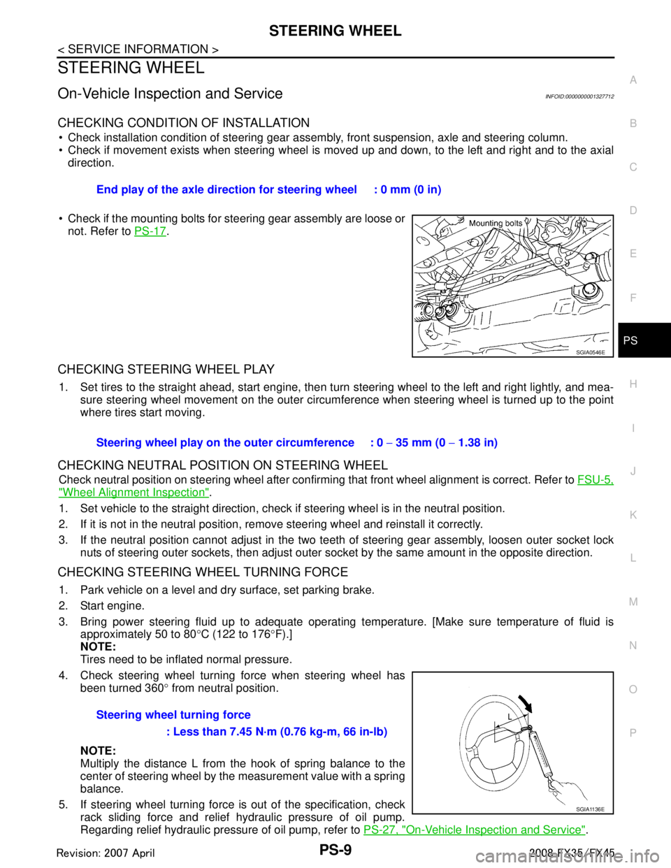
CHECKING CONDITION OF INSTALLATION
Check installation condition of steering gear assemb ly, front suspension, axle and steering column.
Check if movement exists when steering wheel is mo ved up and down, to the left and right and to the axial
direction.
Check if the mounting bolts for steering gear assembly are loose or not. Refer to PS-17
.
CHECKING STEERING WHEEL PLAY
1. Set tires to the straight ahead, start engine, then turn steering wheel to the left and right lightly, and mea-
sure steering wheel movement on the outer circumfe rence when steering wheel is turned up to the point
where tires start moving.
CHECKING NEUTRAL POSITION ON STEERING WHEEL
Check neutral position on steering wheel after confirming that front wheel alignment is correct. Refer to FSU-5,
"Wheel Alignment Inspection".
1. Set vehicle to the straight direction, chec k if steering wheel is in the neutral position.
2. If it is not in the neutral position, remo ve steering wheel and reinstall it correctly.
3. If the neutral position cannot adjust in the two teeth of steering gear assembly, loosen outer socket lock
nuts of steering outer sockets, then adjust outer so cket by the same amount in the opposite direction.
CHECKING STEERING WHEEL TURNING FORCE
1. Park vehicle on a level and dry surface, set parking brake.
2. Start engine.
3. Bring power steering fluid up to adequate operating te mperature. [Make sure temperature of fluid is
approximately 50 to 80 °C (122 to 176 °F).]
NOTE:
Tires need to be inflated normal pressure.
4. Check steering wheel turning force when steering wheel has been turned 360 ° from neutral position.
NOTE:
Multiply the distance L from the hook of spring balance to the
center of steering wheel by the measurement value with a spring
balance.
5. If steering wheel turning force is out of the specification, check
rack sliding force and relief hydraulic pressure of oil pump.
Regarding relief hydraulic pressure of oil pump, refer to PS-27, "
On-Vehicle Inspection and Service".
End play of the axle direction for steering wheel : 0 mm (0 in)
SGIA0546E
Steering wheel play on the
outer circumference : 0 − 35 mm (0 − 1.38 in)
Steering wheel turning force : Less than 7.45 N·m (0.76 kg-m, 66 in-lb)
SGIA1136E
3AA93ABC3ACD3AC03ACA3AC03AC63AC53A913A773A893A873A873A8E3A773A983AC73AC93AC03AC3
3A893A873A873A8F3A773A9D3AAF3A8A3A8C3A863A9D3AAF3A8B3A8C
Page 3744 of 3924

PRECAUTIONSSRS-7
< SERVICE INFORMATION >
C
DE
F
G
I
J
K L
M A
B
SRS
N
O P
PRECAUTIONS
Precaution for Supplemental Restraint System (SRS) "AIR BAG" and "SEAT BELT
PRE-TENSIONER"
INFOID:0000000001612877
The Supplemental Restraint System such as “A IR BAG” and “SEAT BELT PRE-TENSIONER”, used along
with a front seat belt, helps to reduce the risk or severi ty of injury to the driver and front passenger for certain
types of collision. This system includes seat belt switch inputs and dual stage front air bag modules. The SRS
system uses the seat belt switches to determine the front air bag deployment, and may only deploy one front
air bag, depending on the severity of a collision and whether the front occupants are belted or unbelted.
Information necessary to service the system safely is included in the “SUPPLEMENTAL RESTRAINT SYS-
TEM” and “SEAT BELTS” of this Service Manual.
WARNING:
• To avoid rendering the SRS inoper ative, which could increase the risk of personal injury or death in
the event of a collision which would result in air bag inflation, all maintenance must be performed by
an authorized NISSAN/INFINITI dealer.
Improper maintenance, including in correct removal and installation of the SRS, can lead to personal
injury caused by unintentional act ivation of the system. For removal of Spiral Cable and Air Bag
Module, see the “SUPPLEMEN TAL RESTRAINT SYSTEM”.
Do not use electrical test equipm ent on any circuit related to the SRS unless instructed to in this
Service Manual. SRS wiring harnesses can be identi fied by yellow and/or orange harnesses or har-
ness connectors.
Precaution for SRS "AIR BAG" and "SEAT BELT PRE-TENSIONER" Service
INFOID:0000000001327741
Do not use electrical test equipment to check SRS ci rcuits unless instructed to in this Service Manual.
Before servicing the SRS, turn ignition switch OFF, disconnect both battery cables and wait at least 3 min-
utes.
For approximately 3 minutes after the cables are remov ed, it is still possible for the air bag and seat belt pre-
tensioner to deploy. Therefore, do not work on any SR S connectors or wires until at least 3 minutes have
passed.
Diagnosis sensor unit must always be installed with their arrow marks “ ⇐” pointing towards the front of the
vehicle for proper operation. Also check diagnosis sensor unit for cracks, deformities or rust before installa-
tion and replace as required.
The spiral cable must be aligned with the neutral position since its rotations are limited. Do not turn steering
wheel and column after removal of steering gear.
Handle air bag module carefully. Always place driver and front passenger air bag modules with the pad side facing upward and seat mounted front side air bag module standing with the stud bolt side facing down.
Conduct self-diagnosis to check entire SRS for proper function after replacing any components.
After air bag inflates, the front instrument panel assembly should be replaced if damaged.
Always replace instrument panel pad following front passenger air bag deployment.
Disposal, recycling, and transportation of air bag m odules and seat belt pre-tensioners should be performed
in compliance with applicable federal, state and local laws and regulations.
Occupant Classification System PrecautionINFOID:0000000001327742
Replace occupant classification system control uni t and passenger front seat cushion as an assembly.
Refer to Refer to Service Manual .
3AA93ABC3ACD3AC03ACA3AC03AC63AC53A913A773A893A873A873A8E3A773A983AC73AC93AC03AC3
3A893A873A873A8F3A773A9D3AAF3A8A3A8C3A863A9D3AAF3A8B3A8C
Page 3784 of 3924
COLLISION DIAGNOSISSRS-47
< SERVICE INFORMATION >
C
DE
F
G
I
J
K L
M A
B
SRS
N
O P
COLLISION DIAGNOSIS
For Frontal CollisionINFOID:0000000001327773
To repair the SRS, perform the following steps.
When SRS (except the front side air bag and sidecurt ain air bag modules) is activated in a collision:
1. Replace the diagnosis sensor unit.
2. Remove the air bag modules (except the front side air bag modulesand side curtain air bag modules),
crash zone sensor assembly, bracket andseat belt pre-tensioner assemblies.
3. Check the SRS components using the table below:
- Replace any SRS components showing visible signs of damage (dents,cracks and deformation).
4. Install new air bag modules (except the front side air bag modules and side curtain air bag modules) crash
zone sensor assembly, bracket and seat belt pre-tensioner assemblies.
5. Conduct self-diagnosis using CONSULT-III or “AIR BAG”warning lamp. Refer to SRS-23, "
SRS Operation
Check" for details. Ensure entire SRS operates properly.
When SRS is not acti vated in a collision:
1. Check the SRS components using the table below:
- Replace any SRS components showing visible signs of damage (dents, cracks and deformation).
2. Conduct self-diagnosis using CONSULT-III or “AIR BAG” warning lamp. Refer to SRS-23, "
SRS Operation
Check" for details. Ensure entire SRS operates properly.
When only one front air bag modu le is activated in a collision:
1. Replace the following components:
- Diagnosis sensor unit
- Crash zone sensor
- Activated front air bag and seat belt pre-tensioner.
2. Check the other SRS components using the table below. (Refer to “SRS is NOT activated”.)
- Replace any SRS components showing visible signs of damage (dents, cracks and deformation).
3. Conduct self-diagnosis using CONSULT-III or “AIR BAG” warning lamp. Refer to SRS-23, "
SRS Operation
Check" for details. Ensure entire SRS operates properly.
Only one front air bag may inflate a crash, depending on t he crash severity and whether the front occupants
are belted or unbelted. This does not indicate improper performance of the system. Perform self-diagnosis to
make sure the entire SRS operates properly.
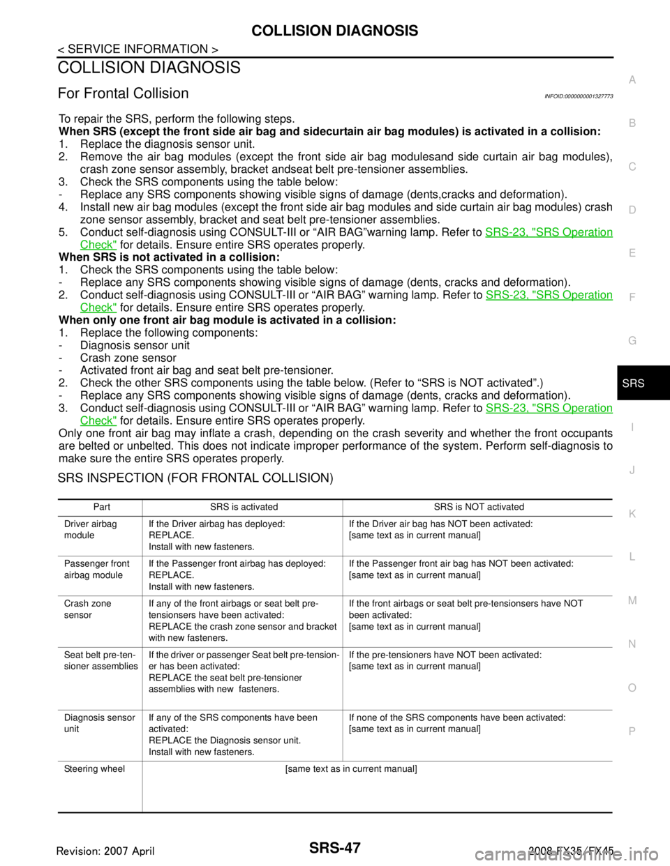
SRS INSPECTION (FOR FRONTAL COLLISION)
Part SRS is activated SRS is NOT activated
Driver airbag
module If the Driver airbag has deployed:
REPLACE.
Install with new fasteners. If the Driver air bag has NOT been activated:
[same text as in current manual]
Passenger front
airbag module If the Passenger front airbag has deployed:
REPLACE.
Install with new fasteners. If the Passenger front air bag has NOT been activated:
[same text as in current manual]
Crash zone
sensor If any of the front airbags or seat belt pre-
tensionsers have been activated:
REPLACE the crash zone sensor and bracket
with new fasteners. If the front airbags or seat belt pre-tensionsers have NOT
been activated:
[same text as in current manual]
Seat belt pre-ten-
sioner assemblies If the driver or passenger Seat belt pre-tension-
er has been activated:
REPLACE the seat belt pre-tensioner
assemblies with new fasteners. If the pre-tensioners have NOT been activated:
[same text as in current manual]
Diagnosis sensor
unit If any of the SRS components have been
activated:
REPLACE the Diagnosis sensor unit.
Install with new fasteners. If none of the SRS components have been activated:
[same text as in current manual]
Steering wheel [same text as in current manual]
3AA93ABC3ACD3AC03ACA3AC03AC63AC53A913A773A893A873A873A8E3A773A983AC73AC93AC03AC3
3A893A873A873A8F3A773A9D3AAF3A8A3A8C3A863A9D3AAF3A8B3A8C
Page 3841 of 3924

WT-1
SUSPENSION
C
DF
G H
I
J
K L
M
SECTION WT
A
B
WT
N
O PCONTENTS
ROAD WHEELS & TIRES
SERVICE INFORMATION .. ..........................2
INDEX FOR DTC ............................................ .....2
DTC No. Index .................................................... ......2
PRECAUTIONS ...................................................3
Precaution for Supplemental Restraint System
(SRS) "AIR BAG" and "SEAT BELT PRE-TEN-
SIONER" ............................................................. ......
3
Precaution .................................................................3
Service Notice or Precaution .....................................4
PREPARATION ...................................................5
Special Service Tool ........................................... ......5
Commercial Service Tool ..........................................5
NOISE, VIBRATION AND HARSHNESS
(NVH) TROUBLESHOOTING .............................
6
NVH Troubleshooting Chart ................................ ......6
ROAD WHEEL ....................................................7
Inspection ............................................................ ......7
ROAD WHEEL TIRE ASSEMBLY ......................8
Balancing Wheels (Bonding Weight Type) .......... ......8
Tire Rotation ..............................................................9
TIRE PRESSURE MONITORING SYSTEM .......10
System Component ............................................. ....10
System Description .................................................10
CAN COMMUNICATION ....................................13
System Description ............................................. ....13
TROUBLE DIAGNOSES ....................................14
Schematic ........................................................... ....14
Wiring Diagram- T/WARN - .....................................15
Control Unit Input/Output Signal Standard ..............17
ID Registration Procedure ................................... ....19
Transmitter Wake Up Operation ..............................20
Self-Diagnosis .........................................................20
CONSULT-III Function (BCM) .................................22
How to Perform Trouble Diagnosis for Quick and
Accurate Repair .......................................................
24
Preliminary Check ...................................................25
Malfunction Code/Symptom Chart ...........................26
TROUBLE DIAGNOSIS FOR SELF-DIAG-
NOSTIC ITEMS .................................................
28
Transmitter or Control Unit (BCM) ...........................28
Transmitter - 1 .........................................................28
Transmitter - 2 .........................................................29
Vehicle Speed Signal ..............................................29
TROUBLE DIAGNOSIS FOR SYMPTOMS ......30
Low Tire Pressure Warning Lamp Does Not Come
On When Ignition Switch Is Turned On ...................
30
Low Tire Pressure Warning Lamp Stays On When
Ignition Switch Is Turned On ............................... ....
30
Low Tire Pressure Warning Lamp Blinks When Ig-
nition Switch Is Turned On ......................................
31
Run-Flat Tire Warning Lamp Stays On When Igni-
tion Switch Is Turned On .........................................
32
Turn Signal Lamp Blinks When Ignition Switch Is
Turned On ...............................................................
32
ID Registration Cannot Be Completed ....................32
REMOVAL AND INSTALLATION .....................33
Transmitter ..............................................................33
SERVICE DATA AND SPECIFICATIONS
(SDS) .................................................................
35
Road Wheel .............................................................35
Tire ..........................................................................35
3AA93ABC3ACD3AC03ACA3AC03AC63AC53A913A773A893A873A873A8E3A773A983AC73AC93AC03AC3
3A893A873A873A8F3A773A9D3AAF3A8A3A8C3A863A9D3AAF3A8B3A8C
Page 3842 of 3924
WT-2
< SERVICE INFORMATION >
INDEX FOR DTC
SERVICE INFORMATION
INDEX FOR DTC
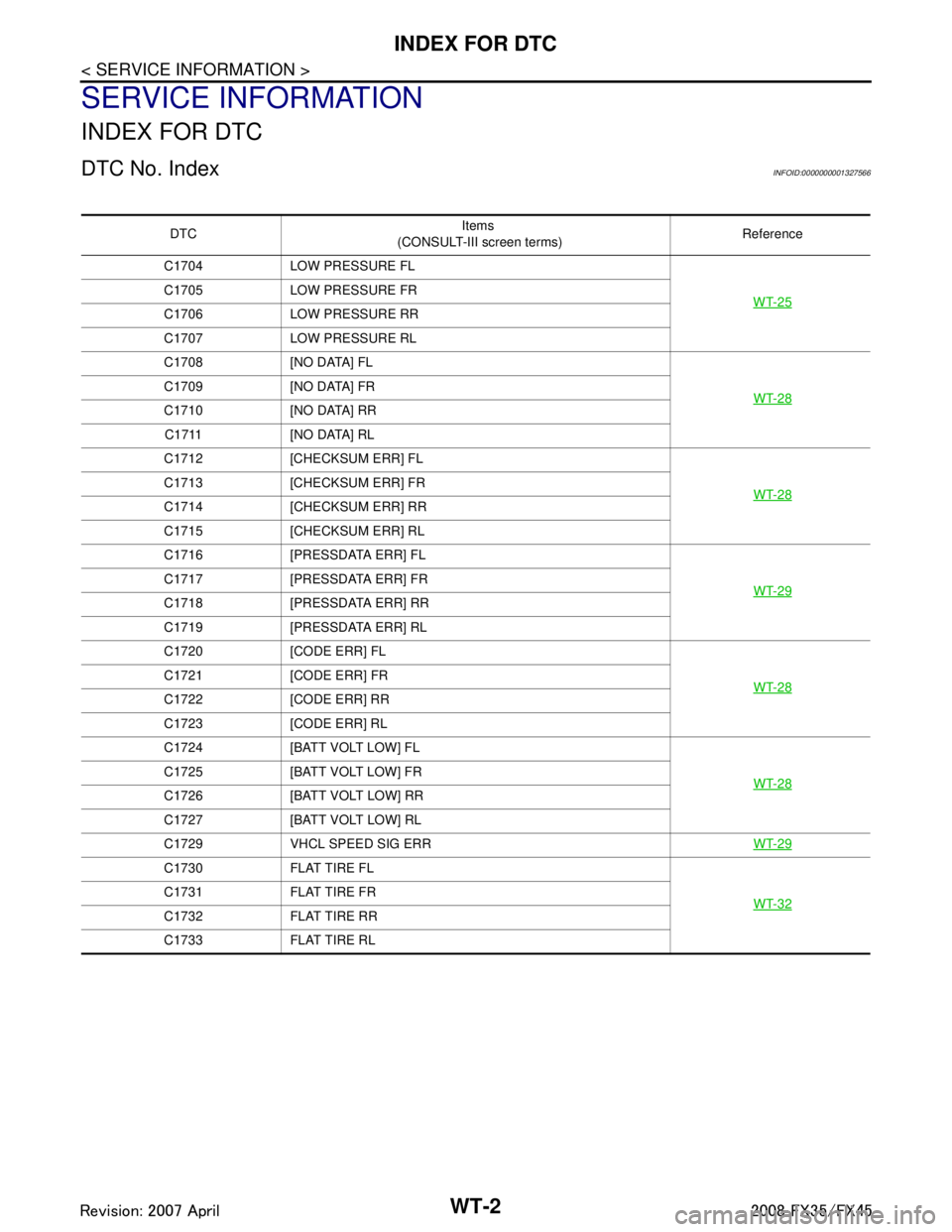
DTC No. IndexINFOID:0000000001327566
DTCItems
(CONSULT-III screen terms) Reference
C1704 LOW PRESSURE FL
WT-25
C1705 LOW PRESSURE FR
C1706 LOW PRESSURE RR
C1707 LOW PRESSURE RL
C1708 [NO DATA] FLWT-28
C1709 [NO DATA] FR
C1710 [NO DATA] RRC1711 [NO DATA] RL
C1712 [CHECKSUM ERR] FL
WT-28
C1713 [CHECKSUM ERR] FR
C1714 [CHECKSUM ERR] RR
C1715 [CHECKSUM ERR] RL
C1716 [PRESSDATA ERR] FLWT-29
C1717 [PRESSDATA ERR] FR
C1718 [PRESSDATA ERR] RR
C1719 [PRESSDATA ERR] RL
C1720 [CODE ERR] FLWT-28
C1721 [CODE ERR] FR
C1722 [CODE ERR] RR
C1723 [CODE ERR] RL
C1724 [BATT VOLT LOW] FLWT-28
C1725 [BATT VOLT LOW] FR
C1726 [BATT VOLT LOW] RR
C1727 [BATT VOLT LOW] RL
C1729 VHCL SPEED SIG ERRWT-29
C1730 FLAT TIRE FL
WT-32
C1731 FLAT TIRE FR
C1732 FLAT TIRE RR
C1733 FLAT TIRE RL
3AA93ABC3ACD3AC03ACA3AC03AC63AC53A913A773A893A873A873A8E3A773A983AC73AC93AC03AC3
3A893A873A873A8F3A773A9D3AAF3A8A3A8C3A863A9D3AAF3A8B3A8C
Page 3847 of 3924
ROAD WHEELWT-7
< SERVICE INFORMATION >
C
DF
G H
I
J
K L
M A
B
WT
N
O P
ROAD WHEEL
InspectionINFOID:0000000001327573
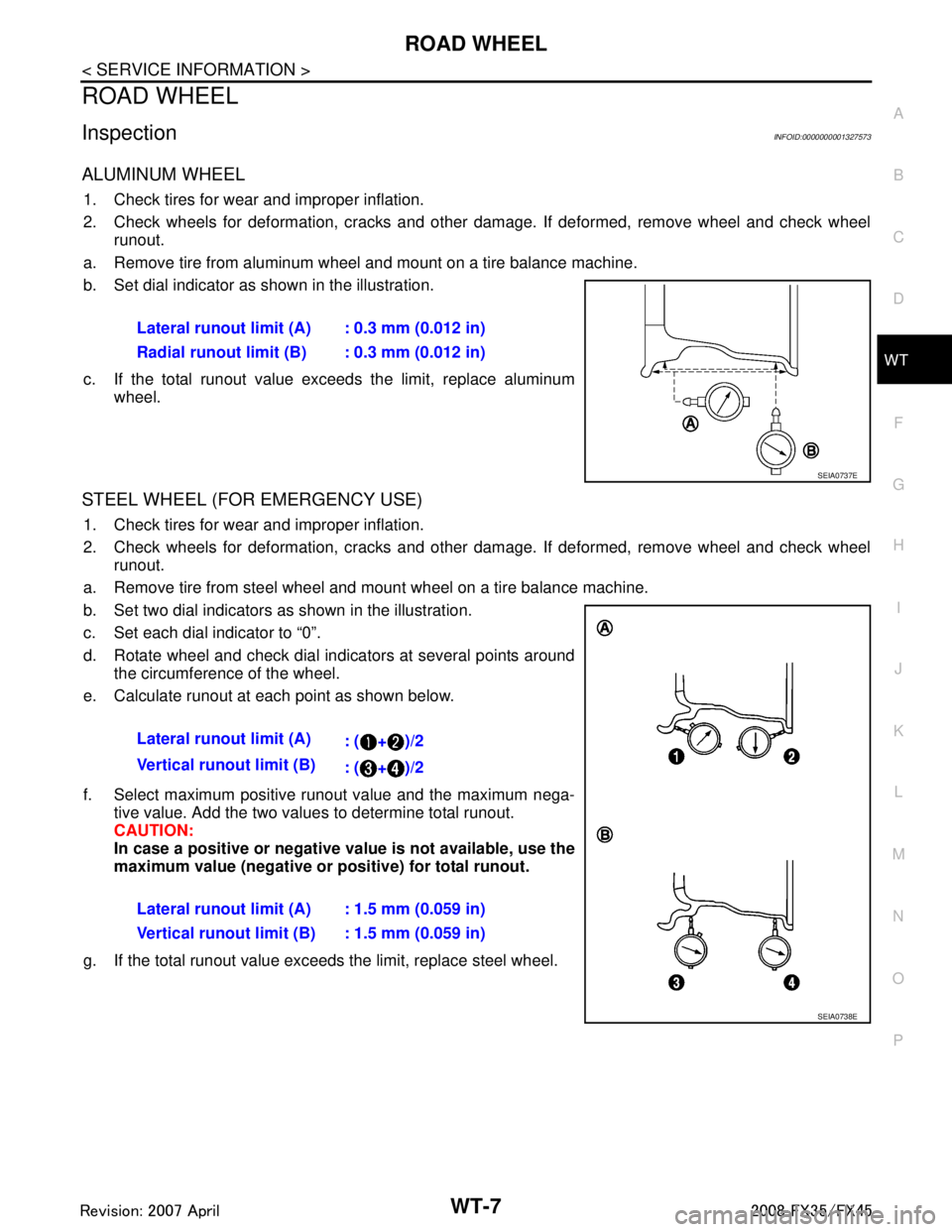
ALUMINUM WHEEL
1. Check tires for wear and improper inflation.
2. Check wheels for deformation, cracks and other damage. If deformed, remove wheel and check wheel runout.
a. Remove tire from aluminum wheel and mount on a tire balance machine.
b. Set dial indicator as shown in the illustration.
c. If the total runout value exceeds the limit, replace aluminum wheel.
STEEL WHEEL (FOR EMERGENCY USE)
1. Check tires for wear and improper inflation.
2. Check wheels for deformation, cracks and other damage. If deformed, remove wheel and check wheelrunout.
a. Remove tire from steel wheel and mount wheel on a tire balance machine.
b. Set two dial indicators as shown in the illustration.
c. Set each dial indicator to “0”.
d. Rotate wheel and check dial indicators at several points around the circumference of the wheel.
e. Calculate runout at each point as shown below.
f. Select maximum positive runout value and the maximum nega- tive value. Add the two values to determine total runout.
CAUTION:
In case a positive or negative val ue is not available, use the
maximum value (negative or positive) for total runout.
g. If the total runout value exceeds the limit, replace steel wheel.
Lateral runout limit (A) : 0.3 mm (0.012 in)
Radial runout limit (B) : 0.3 mm (0.012 in)
SEIA0737E
Lateral runout limit (A)
: ( + )/2
Vertical runout limit (B) : ( + )/2
Lateral runout limit (A) : 1.5 mm (0.059 in)
Vertical runout limit (B) : 1.5 mm (0.059 in)
SEIA0738E
3AA93ABC3ACD3AC03ACA3AC03AC63AC53A913A773A893A873A873A8E3A773A983AC73AC93AC03AC3
3A893A873A873A8F3A773A9D3AAF3A8A3A8C3A863A9D3AAF3A8B3A8C
Page 3851 of 3924
TIRE PRESSURE MONITORING SYSTEMWT-11
< SERVICE INFORMATION >
C
DF
G H
I
J
K L
M A
B
WT
N
O P
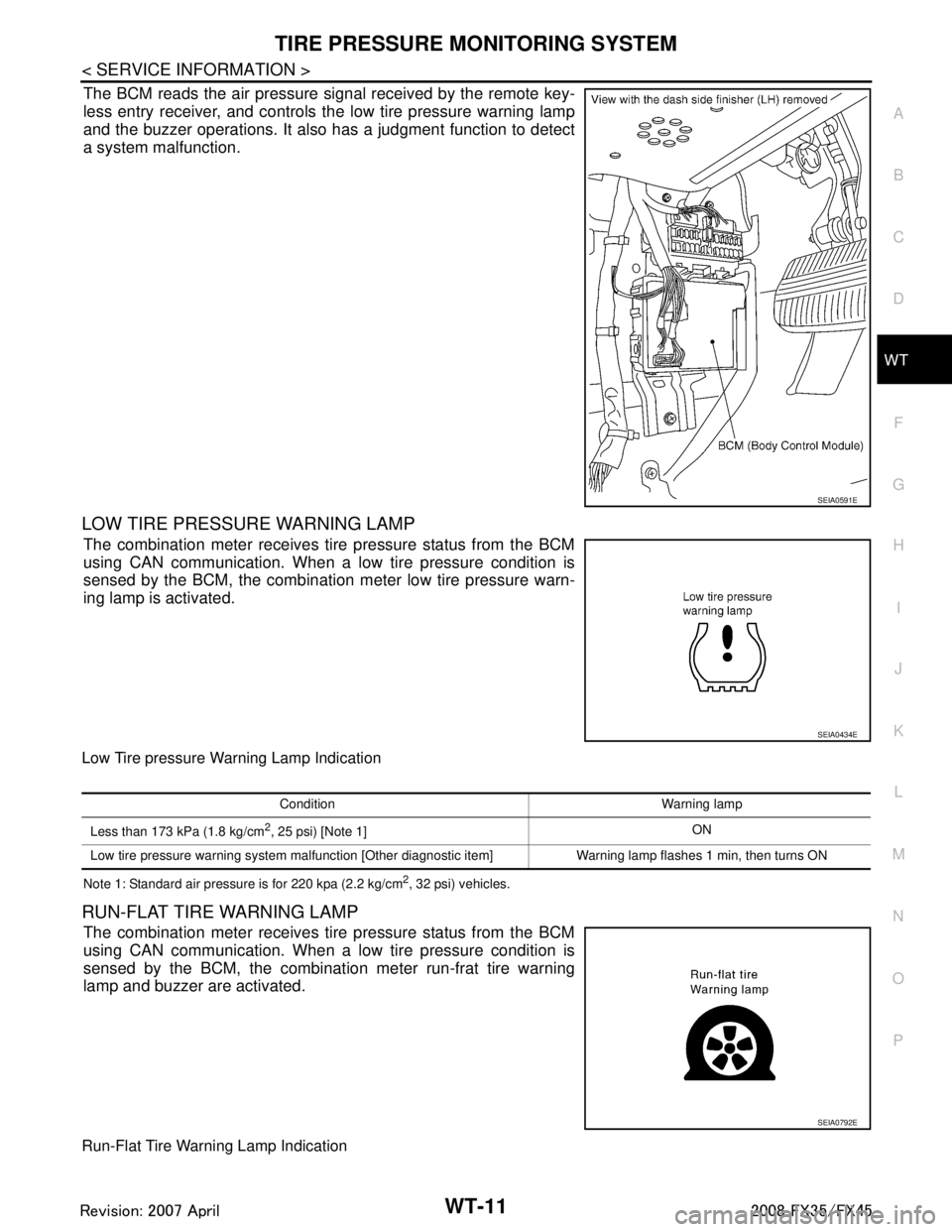
The BCM reads the air pressure signal received by the remote key-
less entry receiver, and controls the low tire pressure warning lamp
and the buzzer operations. It also has a judgment function to detect
a system malfunction.
LOW TIRE PRESSURE WARNING LAMP
The combination meter receives tire pressure status from the BCM
using CAN communication. When a low tire pressure condition is
sensed by the BCM, the combination meter low tire pressure warn-
ing lamp is activated.
Low Tire pressure Warning Lamp Indication
Note 1: Standard air pressure is for 220 kpa (2.2 kg/cm2, 32 psi) vehicles.
RUN-FLAT TIRE WARNING LAMP
The combination meter receives tire pressure status from the BCM
using CAN communication. When a low tire pressure condition is
sensed by the BCM, the combination meter run-frat tire warning
lamp and buzzer are activated.
Run-Flat Tire Warning Lamp Indication
SEIA0591E
SEIA0434E
Condition Warning lamp
Less than 173 kPa (1.8 kg/cm
2, 25 psi) [Note 1] ON
Low tire pressure warning system malfunction [Other diagnostic item] Warning lamp flashes 1 min, then turns ON
SEIA0792E
3AA93ABC3ACD3AC03ACA3AC03AC63AC53A913A773A893A873A873A8E3A773A983AC73AC93AC03AC3
3A893A873A873A8F3A773A9D3AAF3A8A3A8C3A863A9D3AAF3A8B3A8C
Page 3860 of 3924
WT-20
< SERVICE INFORMATION >
TROUBLE DIAGNOSES
4. Inflate all tires to proper pressure. Refer to WT-35, "Tire".
Transmitter Wake Up OperationINFOID:0000000001327583
W I T H A C T I VAT I O N T O O L
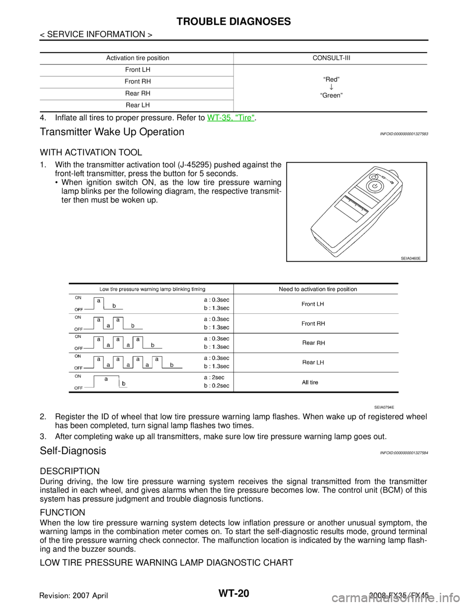
1. With the transmitter activation tool (J-45295) pushed against the
front-left transmitter, press the button for 5 seconds.
When ignition switch ON, as the low tire pressure warninglamp blinks per the following diagram, the respective transmit-
ter then must be woken up.
2. Register the ID of wheel that low tire pressure warning lamp flashes. When wake up of registered wheel
has been completed, turn signal lamp flashes two times.
3. After completing wake up all transmitters, make sure low tire pressure warning lamp goes out.
Self-DiagnosisINFOID:0000000001327584
DESCRIPTION
During driving, the low tire pressure warning syste m receives the signal transmitted from the transmitter
installed in each wheel, and gives alarms when the tire pressure becomes low. The control unit (BCM) of this
system has pressure judgment and trouble diagnosis functions.
FUNCTION
When the low tire pressure warning system detects low inflation pressure or another unusual symptom, the
warning lamps in the combination meter comes on. To start the self-diagnostic results mode, ground terminal
of the tire pressure warning check connector. The malf unction location is indicated by the warning lamp flash-
ing and the buzzer sounds.
LOW TIRE PRESSURE WARNING LAMP DIAGNOSTIC CHART
Activation tire position CONSULT-III
Front LH “Red”↓
“Green”
Front RH
Rear RHRear LH
SEIA0460E
SEIA0794E
3AA93ABC3ACD3AC03ACA3AC03AC63AC53A913A773A893A873A873A8E3A773A983AC73AC93AC03AC3
3A893A873A873A8F3A773A9D3AAF3A8A3A8C3A863A9D3AAF3A8B3A8C