2008 INFINITI FX35 alternator
[x] Cancel search: alternatorPage 3328 of 3924
ENGINE MAINTENANCE (VQ35DE ENGINE)MA-11
< SERVICE INFORMATION >
C
DE
F
G H
I
J
K
M A
B
MA
N
O P
ENGINE MAINTENANCE (VQ35DE ENGINE)
Checking Drive BeltsINFOID:0000000001328900
WARNING:
Be sure to perform when engine is stopped.
1. Inspect belts for cracks, fraying, wear and oil. If necessary, replace.
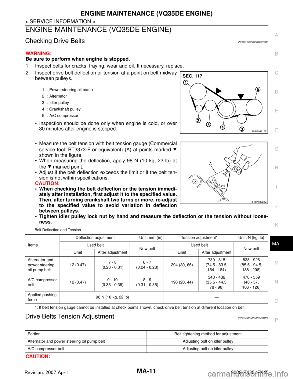
2. Inspect drive belt deflection or tension at a point on belt midway
between pulleys.
Inspection should be done only when engine is cold, or over 30 minutes after engine is stopped.
Measure the belt tension with belt tension gauge (Commercial service tool: BT3373-F or equivalent) (A) at points marked
shown in the figure.
When measuring the deflection, apply 98 N (10 kg, 22 lb) at
the marked point.
Adjust if the belt deflection exceeds the limit or if the belt ten- sion is not within specifications.
CAUTION:
• When checking the belt deflect ion or the tension immedi-
ately after installation, first ad just it to the specified value.
Then, after turning crankshaft two turns or more, re-adjust
to the specified value to avo id variation in deflection
between pulleys.
Tighten idler pulley lock nut by hand and measure the deflection or the tension without loose-
ness.
Belt Deflection and Tension
*: If belt tension gauge cannot be installed at check points shown, check drive belt tension at different location on belt.
Drive Belts Tension AdjustmentINFOID:0000000001328901
CAUTION:
1 : Power steering oil pump
2 : Alternator
3 : Idler pulley
4 : Crankshaft pulley
5 : A/C compressor
JPBIA0421ZZ
JPBIA0422ZZ
Items Deflection adjustment Unit: mm (in) Tension adjustment* Unit: N (kg, lb)
Used belt New beltUsed belt
New belt
Limit After adjustment Limit After adjustment
Alternator and
power steering
oil pump belt 12 (0.47)
7 - 8
(0.28 - 0.31) 6 - 7
(0.24 - 0.28) 294 (30, 66) 730 - 818
(74.5 - 83.5, 164 - 184) 838 - 926
(85.5 - 94.5, 188 - 208)
A/C compressor
belt 12 (0.47)9 - 10
(0.35 - 0.39) 8 - 9
(0.31 - 0.35) 196 (20, 44) 348 - 436
(35.5 - 44.5, 78 - 98) 470 - 559
(48 - 57,
106 - 126)
Applied pushing
force 98 N (10 kg, 22 lb) —
Portion
Belt tightening method for adjustment
Alternator and power steering oil pump belt Adjusting bolt on idler pulley
A/C compressor belt Adjusting bolt on idler pulley
3AA93ABC3ACD3AC03ACA3AC03AC63AC53A913A773A893A873A873A8E3A773A983AC73AC93AC03AC3
3A893A873A873A8F3A773A9D3AAF3A8A3A8C3A863A9D3AAF3A8B3A8C
Page 3329 of 3924
MA-12
< SERVICE INFORMATION >
ENGINE MAINTENANCE (VQ35DE ENGINE)
When belt is replaced with a new one, adjust it to value for “New belt” to accommodate for insuffi-
cient adaptability with pulley grooves.
When deflection or tension of belt being used exceeds “Limit”, adjust it to value for “After adjust-
ment”.
When checking belt deflection or te nsion immediately after installation, first adjust it to the specified
value. Then, after turning crankshaft two turns or mo re, re-adjust to the specified value to avoid vari-
ation in deflection between pulleys.
When installing belt, make sure that it is correctly engaged with pulley grooves.
Keep engine oil, working fluid and engine coolant away from belt and pulley grooves.
Do not twist or bend belt excessively.
ALTERNATOR AND POWER STEERING OIL PUMP BELT
1. Remove front engine undercover with power tool.
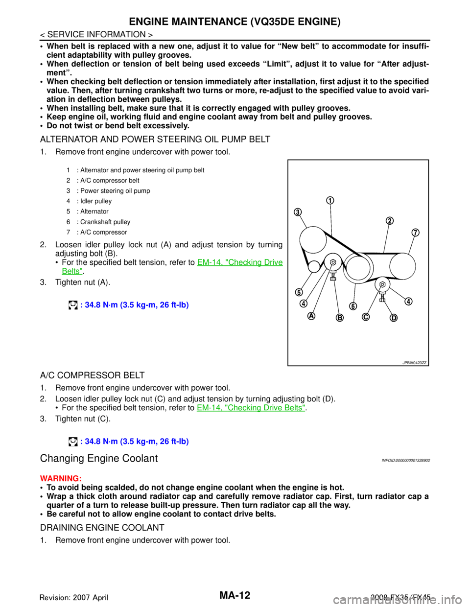
2. Loosen idler pulley lock nut (A) and adjust tension by turning adjusting bolt (B).
For the specified belt tension, refer to EM-14, "
Checking Drive
Belts".
3. Tighten nut (A).
A/C COMPRESSOR BELT
1. Remove front engine undercover with power tool.
2. Loosen idler pulley lock nut (C) and adjust tension by turning adjusting bolt (D). For the specified belt tension, refer to EM-14, "
Checking Drive Belts".
3. Tighten nut (C).
Changing Engine CoolantINFOID:0000000001328902
WARNING:
To avoid being scalded, do not change en gine coolant when the engine is hot.
Wrap a thick cloth around radiator cap and carefully remove radiator cap. First, turn radiator cap a
quarter of a turn to release built-up pressu re. Then turn radiator cap all the way.
Be careful not to allow engine coolant to contact drive belts.
DRAINING ENGINE COOLANT
1. Remove front engine undercover with power tool.
1 : Alternator and power steering oil pump belt
2: A/C compressor belt
3 : Power steering oil pump
4 : Idler pulley
5 : Alternator
6 : Crankshaft pulley
7: A/C compressor
: 34.8 N·m (3.5 kg-m, 26 ft-lb)
JPBIA0423ZZ
: 34.8 N·m (3.5 kg-m, 26 ft-lb)
3AA93ABC3ACD3AC03ACA3AC03AC63AC53A913A773A893A873A873A8E3A773A983AC73AC93AC03AC3
3A893A873A873A8F3A773A9D3AAF3A8A3A8C3A863A9D3AAF3A8B3A8C
Page 3336 of 3924
ENGINE MAINTENANCE (VK45DE ENGINE)MA-19
< SERVICE INFORMATION >
C
DE
F
G H
I
J
K
M A
B
MA
N
O P
ENGINE MAINTENANCE (VK45DE ENGINE)
Checking Drive BeltsINFOID:0000000001328909
WARNING:
Be sure to perform when the engine is stopped.
Remove air duct (inlet) when inspecting drive belt for alternator, water pump and A/C compressor.
Remove front engine undercover with power tool when inspecting power steering oil pump belt.
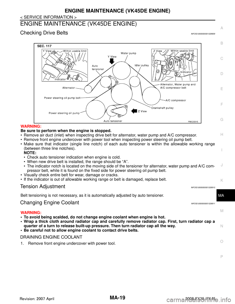
Make sure that indicator (single line notch) of eac h auto tensioner is within the allowable working range
(between three line notches).
NOTE:
Check auto tensioner indication when engine is cold.
When new drive belt is installed, the range should be “A”.
The indicator notch is located on the moving side of the tensioner for alternator, water pump and A/C com-
pressor belt, while it is found on the fi xed side for power steering oil pump belt.
Visually check entire belt for wear, damage or cracks.
If the indicator is out of allowable working range or belt is damaged, replace belt.
Tension AdjustmentINFOID:0000000001328910
Belt tensioning is not necessary, as it is automatically adjusted by auto tensioner.
Changing Engine CoolantINFOID:0000000001328911
WARNING:
To avoid being scalded, do not change engine coolant when engine is hot.
Wrap a thick cloth around radiator cap and carefully remove radiator cap. First, turn radiator cap a
quarter of a turn to release built-up pressu re. Then turn radiator cap all the way.
Be careful not to allow engine coolant to contact drive belts.
DRAINING ENGINE COOLANT
1. Remove front engine undercover with power tool.
PBIC2331E
3AA93ABC3ACD3AC03ACA3AC03AC63AC53A913A773A893A873A873A8E3A773A983AC73AC93AC03AC3
3A893A873A873A8F3A773A9D3AAF3A8A3A8C3A863A9D3AAF3A8B3A8C
Page 3354 of 3924
SERVICE DATA AND SPECIFICATIONS (SDS)
MA-37
< SERVICE INFORMATION >
C
D E
F
G H
I
J
K
M A
B
MA
N
O P
SERVICE DATA AND SPECIFICATIONS (SDS)
Standard and LimitINFOID:0000000001328938
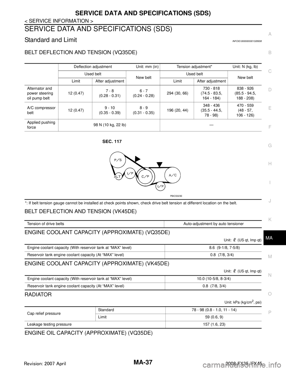
BELT DEFLECTION AND TENSION (VQ35DE)
*: If belt tension gauge cannot be installed at check points shown, check drive belt tension at different location on the belt.
BELT DEFLECTION AND TENSION (VK45DE)
ENGINE COOLANT CAPACITY (APPROXIMATE) (VQ35DE)
Unit: (US qt, lmp qt)
ENGINE COOLANT CAPACITY (APPROXIMATE) (VK45DE)
Unit: (US qt, lmp qt)
RADIATOR
Unit: kPa (kg/cm2, psi)
ENGINE OIL CAPACITY (APPROXIMATE) (VQ35DE)
Deflection adjustment Unit: mm (in) Tension adjustment* Unit: N (kg, lb) Used belt New beltUsed belt
New belt
Limit After adjustment Limit After adjustment
Alternator and
power steering
oil pump belt 12 (0.47)
7 - 8
(0.28 - 0.31) 6 - 7
(0.24 - 0.28) 294 (30, 66) 730 - 818
(74.5 - 83.5, 164 - 184) 838 - 926
(85.5 - 94.5, 188 - 208)
A/C compressor
belt 12 (0.47)
9 - 10
(0.35 - 0.39) 8 - 9
(0.31 - 0.35) 196 (20, 44) 348 - 436
(35.5 - 44.5,
78 - 98) 470 - 559
(48 - 57,
106 - 126)
Applied pushing
force 98 N (10 kg, 22 lb) —
PBIC5323E
Tension of drive belts Auto-adjustment by auto tensioner
Engine coolant capacity (With reservoir tank at “MAX” level) 8.6 (9-1/8, 7-5/8)
Reservoir tank engine coolant capacity (At “MAX” level) 0.8 (7/8, 3/4)
Engine coolant capacity (With reservoir tank at “MAX” level) 10.0 (10-5/8, 8-3/4)
Reservoir tank engine coolant capacity (At “MAX” level) 0.8 (7/8, 3/4)
Cap relief pressure Standard 78 - 98 (0.8 - 1.0, 11 - 14)
Limit 59 (0.6, 9)
Leakage testing pressure 157 (1.6, 23)
3AA93ABC3ACD3AC03ACA3AC03AC63AC53A913A773A893A873A873A8E3A773A983AC73AC93AC03AC3
3A893A873A873A8F3A773A9D3AAF3A8A3A8C3A863A9D3AAF3A8B3A8C
Page 3610 of 3924

SC-1
ELECTRICAL
C
DE
F
G H
I
J
L
M
SECTION SC
A
B
SC
N
O P
CONTENTS
STARTING & CHARGING SYSTEM
SERVICE INFORMATION .. ..........................2
PRECAUTIONS .............................................. .....2
Precaution for Supplemental Restraint System
(SRS) "AIR BAG" and "SEAT BELT PRE-TEN-
SIONER" ............................................................. ......
2
PREPARATION ...................................................3
Special Service Tools .......................................... ......3
Commercial Service Tools ........................................3
BATTERY ............................................................4
How to Handle Battery ........................................ ......4
Trouble Diagnosis with Battery Service Center .........6
Removal and Installation ...........................................6
STARTING SYSTEM ...........................................8
System Description ............................................. ......8
Wiring Diagram - START - ........................................9
Trouble Diagnosis with Starting/Charging System
Tester (Starting) ......................................................
10
Removal and Installation (VK45DE Engine Mod-
els) ..........................................................................
13
Removal and Installation [VQ35DE Engine Mod-
els (2WD)] ............................................................ ....
14
Removal and Installation [VQ35DE Engine Mod-
els (AWD)] ...............................................................
15
Disassembly and Assembly .....................................15
Inspection After Disassembly ..................................18
CHARGING SYSTEM .......................................19
System Description ..................................................19
Wiring Diagram - CHARGE - ...................................20
Trouble Diagnosis with Starting/Charging System
Tester (Charging) ....................................................
21
Removal and Installation (VK45DE Engine Mod-
els) ...........................................................................
25
Removal and Installation (VQ35DE Engine Mod-
els) ...........................................................................
27
Disassembly and Assembly .....................................28
SERVICE DATA AND SPECIFICATIONS
(SDS) .................................................................
30
Battery .....................................................................30
Starter ......................................................................30
Alternator .................................................................30
3AA93ABC3ACD3AC03ACA3AC03AC63AC53A913A773A893A873A873A8E3A773A983AC73AC93AC03AC3
3A893A873A873A8F3A773A9D3AAF3A8A3A8C3A863A9D3AAF3A8B3A8C
Page 3628 of 3924

CHARGING SYSTEMSC-19
< SERVICE INFORMATION >
C
DE
F
G H
I
J
L
M A
B
SC
N
O P
CHARGING SYSTEM
System DescriptionINFOID:0000000001328254
The alternator provides DC voltage to operate the vehi cle's electrical system and to keep the battery charged.
The voltage output is controlled by the IC regulator.
Power is supplied at all times
through 10A fuse (No. 33, located in the fuse and fusible link block)
to alternator terminal 4 (“S” terminal).
“B” Terminal supplies power to charge the battery and oper ate the vehicle's electrical system. Output voltage
is controlled by the IC regulator at terminal 4 (“S” terminal) detecting the input voltage.
The charging circuit is protected by the 120A fusible link (VK45DE and VQ35DE AWD).
The alternator is grounded to the engine block.
With the ignition switch in the ON or START position, power is supplied
through 10A fuse [No. 14, located in the fuse block (J/B)]
to combination meter terminal 7 for the charge warning lamp.
Ground is supplied
to combination meter terminal 2
through alternator terminal 3 (“L” terminal)
to alternator terminal 2 (“E” terminal) (VK45DE) or through case ground (VQ35DE)
through ground E304 (VK45DE).
With power and ground supplied, the charge warning lamp will illuminate. When the alternator is providing suf-
ficient voltage with the engine running, the ground is opened and the charge warning lamp will go off.
If the charge warning lamp illuminates with the engine running, a malfunction is indicated.
MALFUNCTION INDICATOR
The IC regulator warning function activates to illumi nate charge warning lamp, if any of the following symp-
toms occur while alternator is operating:
Excessive voltage is produced.
No voltage is produced.
3AA93ABC3ACD3AC03ACA3AC03AC63AC53A913A773A893A873A873A8E3A773A983AC73AC93AC03AC3
3A893A873A873A8F3A773A9D3AAF3A8A3A8C3A863A9D3AAF3A8B3A8C
Page 3632 of 3924
CHARGING SYSTEMSC-23
< SERVICE INFORMATION >
C
DE
F
G H
I
J
L
M A
B
SC
N
O P
Check if battery terminals are clean and tight.
OK or NG
OK >> GO TO 2.
NG >> Repair battery terminals connection.
2.CHECK FUSE AND FUSIBLE LINK
Check for blown alternator and combination meter fuses.
OK or NG
OK >> GO TO 3.
NG >> If fuse is blown, be sure eliminate cause of malfunction before installing new fuse.
3.CHECK “E” TERMINAL CONNECTION
Check if “E” terminal (alternator ground harness) is clean and tight.
OK or NG
OK >> GO TO 4.
NG >> Repair “E” terminal connection.
4.CHECK ALTERNATOR DRIVE BELT TENSION
Check alternator drive belt tension. Refer to EM-170, "
Checking Drive Belts" (VK45DE) or EM-14, "Checking
Drive Belts" (VQ35DE).
OK or NG
OK >> INSPECTION END
NG >> Repair as needed.
DIAGNOSTIC PROCEDURE 1
Check “L” Terminal Circuit (Open)
1.CHECK “L” TERMINAL CONNECTION
1. Turn ignition switch OFF.
2. Check if “L” terminal is clean and tight.
OK or NG
OK >> GO TO 2.
NG >> Repair “L” terminal connection. Confirm repa ir by performing complete Starting/Charging system
test. Refer to Technical Service Bulletin.
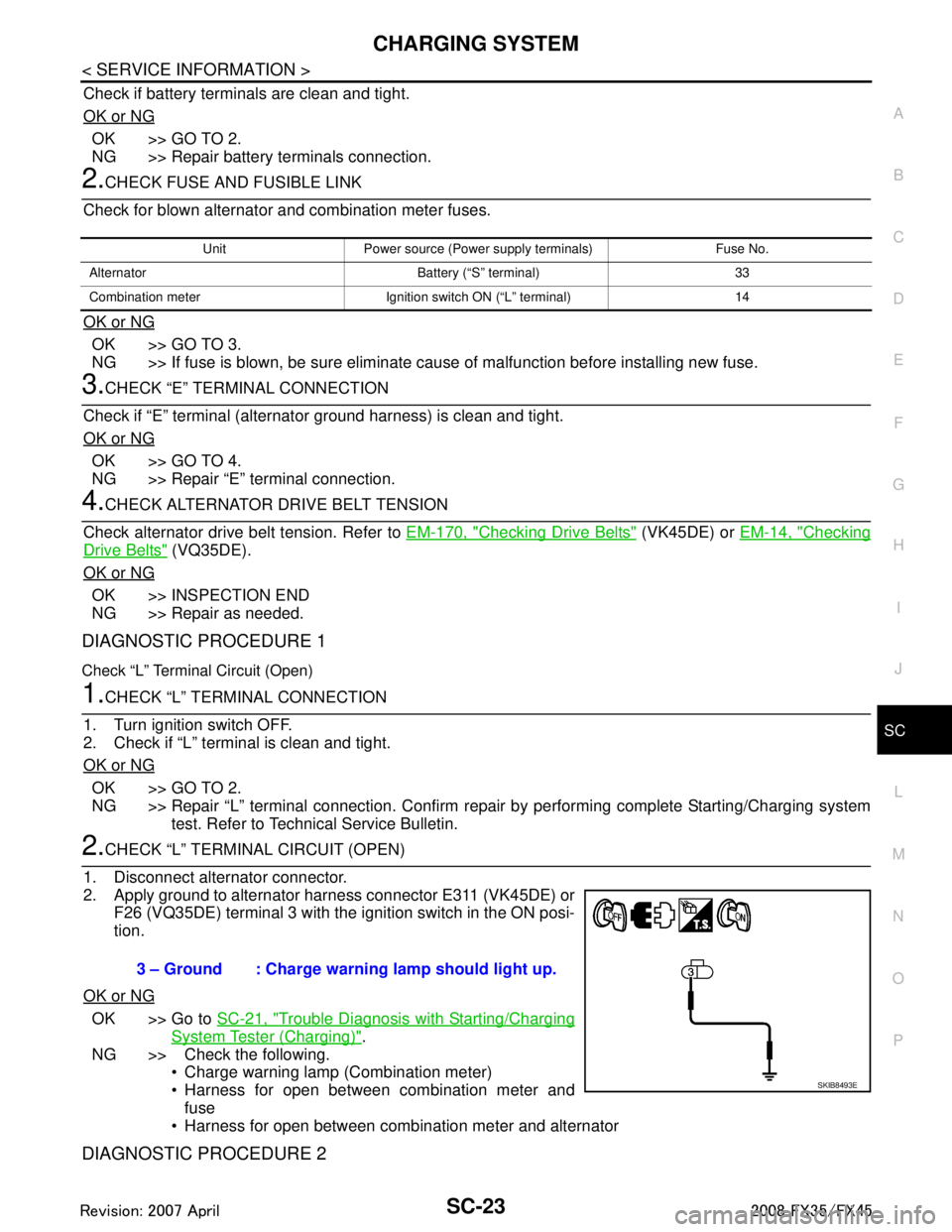
2.CHECK “L” TERMINAL CIRCUIT (OPEN)
1. Disconnect alternator connector.
2. Apply ground to alternator harness connector E311 (VK45DE) or F26 (VQ35DE) terminal 3 with the ignition switch in the ON posi-
tion.
OK or NG
OK >> Go to SC-21, "Trouble Diagnosis with Starting/Charging
System Tester (Charging)".
NG >> Check the following. Charge warning lamp (Combination meter)
Harness for open between combination meter and
fuse
Harness for open between combination meter and alternator
DIAGNOSTIC PROCEDURE 2
Unit Power source (Power supply terminals) Fuse No.
Alternator Battery (“S” terminal) 33
Combination meter Ignition switch ON (“L” terminal) 14
3 – Ground : Charge warning lamp should light up.
SKIB8493E
3AA93ABC3ACD3AC03ACA3AC03AC63AC53A913A773A893A873A873A8E3A773A983AC73AC93AC03AC3
3A893A873A873A8F3A773A9D3AAF3A8A3A8C3A863A9D3AAF3A8B3A8C
Page 3633 of 3924
SC-24
< SERVICE INFORMATION >
CHARGING SYSTEM
Check “L” Terminal Circuit (Short)
1.CHECK “L” TERMINAL CIRCUIT (SHORT)
1. Turn ignition switch OFF.
2. Disconnect alternator connector.
3. Turn ignition switch ON.
Charge warning lamp should light up?
YES >> Check the following. Harness for short between combination meter and alternator
Charge warning lamp (Combination meter)
NO >> Go to SC-21, "
Trouble Diagnosis with Starting/Charging System Tester (Charging)".
DIAGNOSTIC PROCEDURE 3
Check “S” Terminal Circuit
1.CHECK “S” TERMINAL CONNECTION
1. Turn ignition switch OFF.
2. Check if “S” terminal is clean and tight.
OK or NG
OK >> GO TO 2.
NG >> Repair “S” terminal connection. Confirm repair by performing complete Starting/Charging system
test. Refer to Technical Service Bulletin.
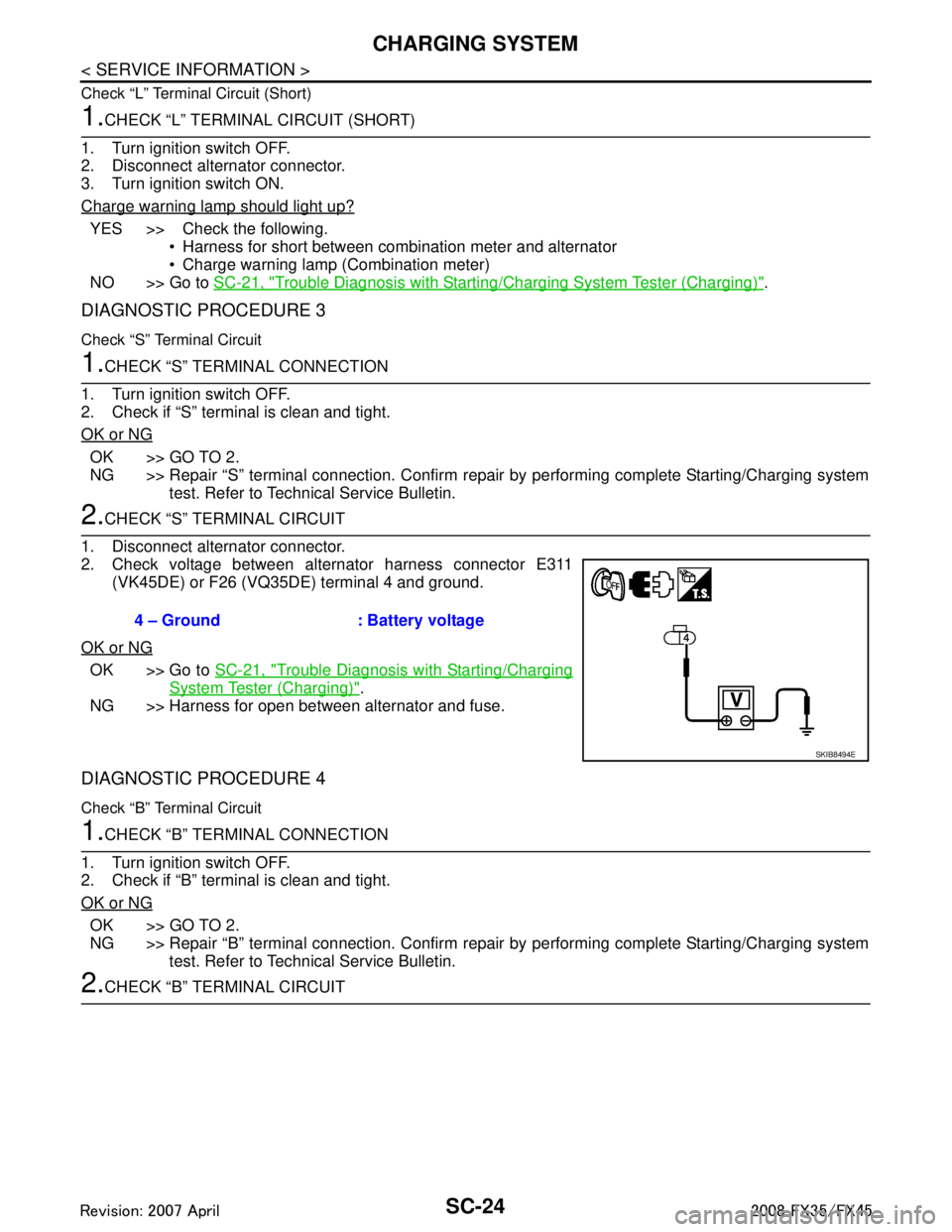
2.CHECK “S” TERMINAL CIRCUIT
1. Disconnect alternator connector.
2. Check voltage between alternator harness connector E311 (VK45DE) or F26 (VQ35DE) terminal 4 and ground.
OK or NG
OK >> Go to SC-21, "Trouble Diagnosis with Starting/Charging
System Tester (Charging)".
NG >> Harness for open between alternator and fuse.
DIAGNOSTIC PROCEDURE 4
Check “B” Terminal Circuit
1.CHECK “B” TERMINAL CONNECTION
1. Turn ignition switch OFF.
2. Check if “B” terminal is clean and tight.
OK or NG
OK >> GO TO 2.
NG >> Repair “B” terminal connection. Confirm repair by performing complete Starting/Charging system
test. Refer to Technical Service Bulletin.
2.CHECK “B” TERMINAL CIRCUIT 4 – Ground : Battery voltage
SKIB8494E
3AA93ABC3ACD3AC03ACA3AC03AC63AC53A913A773A893A873A873A8E3A773A983AC73AC93AC03AC3
3A893A873A873A8F3A773A9D3AAF3A8A3A8C3A863A9D3AAF3A8B3A8C